
What is the implant position criteria and indication for all on 4 immediate implant concept
"All-on-4" implant immediate loading indications
All-on-4 implant concept indications contraindications implant position criteria immediate loading protocol
https://pmc.ncbi.nlm.nih.gov/articles/PMC5347302
All-on-4 implant position tilted posterior implants full arch diagram
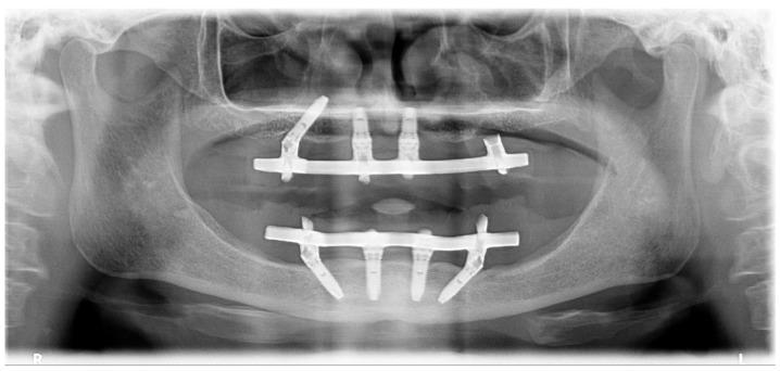
This orthopantomogram (panoramic X-ray) displays a preoperative view of a patient with full-arch dental rehabilitation. The maxilla (upper arch) contains three visible root-form metallic implants; the two anterior implants are vertically oriented, while one posterior implant is distally tilted. A notable absence of a posterior tilted implant is seen in the third sextant. In the mandible (lower arch), four root-form implants are present following the All-on-4 concept: two vertical anterior implants and two mesially tilted posterior implants. Both arches feature radiopaque horizontal bars connected to the implants, stabilizing the prosthetic frameworks. Significant craniofacial landmarks are visualized, including the bilateral temporomandibular joints (TMJs) with defined mandibular condyles, the radiolucent nasal cavity divided by the septum, and bilateral maxillary sinuses. The alveolar bone demonstrates radiographic density and close adaptation to the implant interfaces without significant peri-implant radiolucency. This diagnostic image is used in dental implantology to evaluate bone quantity and prosthetic alignment.
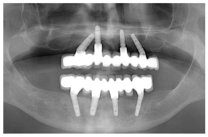
This orthopantomograph (OPG) displays a full-arch dental rehabilitation of both the maxilla and mandible using the All-on-4 treatment concept. In the maxillary arch, four endosseous implants support a fixed radiopaque prosthesis; the two anterior implants are placed vertically, while the two posterior implants are distally tilted to bypass the maxillary sinuses and maximize the prosthetic base. The mandibular arch similarly shows four implants supporting a full-arch prosthesis, with tilted posterior fixtures positioned anterior to the mental foramina. The bone-to-implant interface demonstrates stable peri-implant marginal bone levels at this five-year follow-up, with no significant peri-implant radiolucencies. Key anatomical structures visible include the maxillary sinuses, the nasal cavity floor, and the inferior alveolar nerve canals. This diagnostic image illustrates long-term successful osseointegration and the geometric distribution of implants required for fixed edentulous restoration in oral and maxillofacial surgery.
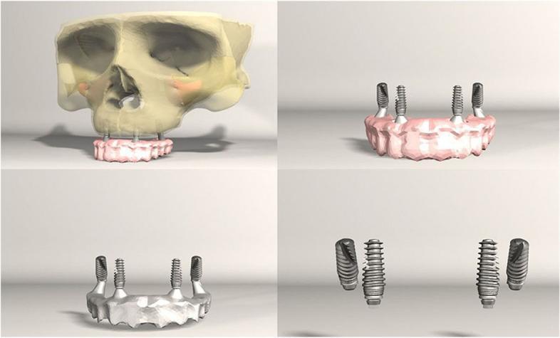
This four-panel anatomical diagram presents a 3D digital model illustrating the structural configuration of dental implants for an 'All-on-4' prosthetic rehabilitation. The upper-left panel shows the complete model with a semi-transparent human maxilla and skull, demonstrating the integration of the dental arch prosthesis and four titanium implants into the alveolar bone. The remaining panels provide isolated views of the prosthetic superstructure and the implant components. The configuration consists of four implants in total: two anterior implants positioned vertically (0° angulation) and two posterior implants tilted distally at an approximate 30° angle. This distal tilting is a common biomechanical strategy to avoid the maxillary sinus while providing a wider prosthetic base to support the dental arch. The diagram serves as an educational tool for dental students and maxillofacial surgeons to visualize implant angulation, spatial distribution within the jawbone, and the relationship between the surgical hardware and the final prosthetic restoration.
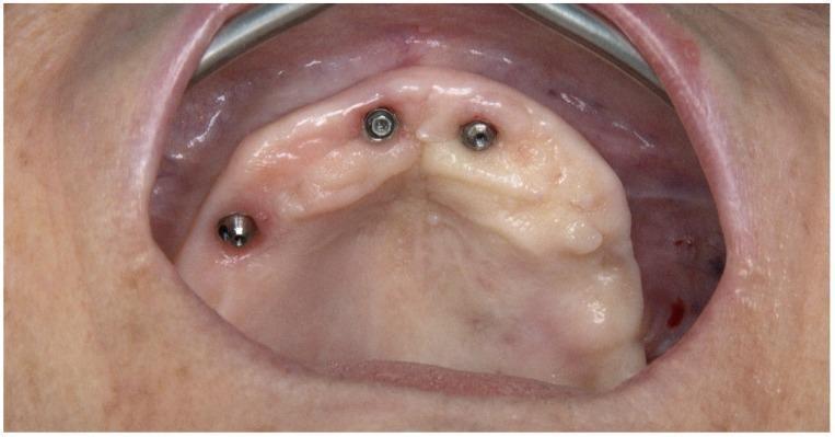
This intraoral photograph provides an occlusal view of a partially edentulous maxilla undergoing full-arch dental rehabilitation. The image depicts three integrated dental implants protruding through the gingival tissue. Two axial implants are positioned anteriorly in the region of the lateral incisors, while a third implant is located in the posterior right quadrant (anatomical left of the image), demonstrating a distal tilt consistent with an 'All-on-4' or hybrid protocol. The metallic, cylindrical implants show exposed screw access channels on their occlusal surfaces. The maxillary arch is U-shaped with a smooth, pale, and vascularized alveolar ridge. Notable findings include the absence of the posterior tilted implant in the third sextant (anatomical right), indicating a site of previous implant failure. The surrounding soft tissue appears healthy and well-adapted around the anterior implants, while the tissue surrounding the posterior tilted implant shows minor surgical irregularities. This clinical image is representative of restorative dentistry and oral surgery, illustrating pre-operative conditions for revision surgery in complex implant cases.
All-on-4 Immediate Implant Concept
1. Overview
2. Indications
Patient-Level Indications
- Complete edentulism - most classic indication
- Failing dentition requiring full-arch extraction (terminal dentition)
- Severe periodontal disease with hopeless remaining teeth
- Atrophic maxilla or mandible where bone grafting is not desired or contraindicated
- Patients preferring to avoid bone grafting - reduced morbidity and cost
- Patients with moderate bone resorption (Cawood & Howell Classes III-V) where conventional axial implant placement is limited by anatomy
Jaw-Specific Indications
| Jaw | Limiting Anatomy Avoided | Rationale for Tilting |
|---|---|---|
| Maxilla | Maxillary sinuses | Posterior implants tilted anteriorly to the antrum |
| Mandible | Mental foramen / inferior alveolar nerve | Posterior implants placed anterior to mental foramen |
Bone Volume Minimum Requirements
- Minimum bone width: 5 mm
- Minimum bone height (maxilla): 10 mm (canine to canine region)
- Minimum bone height (mandible): 8 mm (interforaminal region)
- Residual ridge difficulty classification (Lopes et al.):
- Low difficulty: ridge width >5 mm
- Moderate difficulty: irregular ridge 4-5 mm wide
- High difficulty: irregular ridge <4 mm wide (may need modification)
3. Implant Position Criteria
Implant Configuration (per arch)
| Implant | Position | Angulation |
|---|---|---|
| 2 Anterior implants | Canine/lateral incisor region | Axial (0°, vertical) |
| 2 Posterior implants | Premolar/first molar region | Tilted 30°-45° distally |
Anterior Implants
- Placed vertically (axially) in the anterior region
- Positioned bilaterally between the canines
- Standard placement without angulation
Posterior (Tilted) Implants
- Tilted 30°-45° - the most common angulation described is 30°, with up to 45° depending on anatomy
- In the maxilla: tilted anteriorly (mesially), emerging anterior to the maxillary sinus
- In the mandible: emergence just anterior to the mental foramina
- Screw access holes for tilted posterior implants should emerge at the occlusal surface of the 1st molar, 2nd premolar, or 1st premolar
- The distal position of posterior implants reduces cantilever length, lowering biomechanical stress
Biomechanical Rationale for Tilting
- Tilting the distal implant by 30° decreases stress in compact bone by 52% and in cancellous bone by 47.6% compared to vertical implants with longer cantilevers (Bevilacqua et al.)
- Cross-arch splinting with immediate provisional distributes forces across all 4 implants
- Load is shared between mesial and distal implants through the prosthesis, avoiding overloading
4. Immediate Loading Criteria
Primary Stability (Most Critical)
- Insertion torque: 30-50 Ncm (minimum 30 Ncm to qualify for immediate loading)
- The most commonly reported range is 32-37 Ncm
- Under-preparation of the osteotomy (under-drilling, avoiding countersink) is used to maximize torque
- ISQ (Implant Stability Quotient via Osstell) assessment is an additional option, though not uniformly reported
Surgical Technique to Enhance Primary Stability
- Alveolectomy (removal of some alveolar bone) for 3 reasons:
- To use standard implants in basal bone (denser) for better stability
- To conceal the prosthesis-mucosa transition line aesthetically
- To create adequate restorative space for the prosthesis and multiunit abutments
- Under-drilling the osteotomy site
Prosthetic Requirements for Immediate Loading
- The 4 implants must be splinted by a rigid cross-arch provisional prosthesis within 48 hours
- Splinting provides cross-arch stabilization and controls micromotion (<150 μm threshold)
- The provisional should be screw-retained, not cement-retained
Occlusal Scheme (Immediate Provisional)
- Avoid cantilevers or minimize their length
- Simultaneous bilateral point contacts on all teeth - excluding teeth distal to implant emergence
- In lateral movements: group function or guidance with flat linear pathways and minimal vertical superimposition - no balancing contacts
- In protrusive movements: guidance distributed on all anterior teeth including canines
- If opposing a removable full denture: avoid balancing contacts in excursive movements
Occlusal Scheme (Definitive Prosthesis)
- Full prosthesis typically replaces teeth up to the 1st or 2nd premolar (with a 1-2 premolar cantilever at most)
- Second molars are generally not included
5. Contraindications
- Inadequate primary stability (<30 Ncm insertion torque) - should convert to delayed loading
- Severe uncontrolled systemic disease (uncontrolled diabetes, immunosuppression, bisphosphonate therapy with active disease)
- Bone width <4 mm (very narrow ridge - consider grafting or zygomatic implants)
- Active infection at implant sites
- Uncontrolled bruxism (high occlusal forces - relative contraindication)
- Heavy smoker (relative contraindication, not absolute - increased failure risk)
- Radiation therapy to the jaws (relative contraindication)
6. Implant Specifications Typically Used
- Length: Commonly 13-18 mm (longer implants preferred for posterior tilted positions)
- Diameter: 3.5-5 mm (standard platform)
- Surface: Roughened/sandblasted acid-etched surfaces for osseointegration
- Abutment: Angled multiunit abutments (17°, 30°) used to compensate for implant tilting and create a parallel emergence profile
Summary Table
| Parameter | Criterion |
|---|---|
| No. of implants | 4 |
| Anterior implant angulation | 0° (axial) |
| Posterior implant angulation | 30°-45° (typically 30°) |
| Minimum bone width | 5 mm |
| Minimum bone height (maxilla) | 10 mm (canine-canine) |
| Minimum bone height (mandible) | 8 mm (interforaminal) |
| Insertion torque for immediate loading | 30-50 Ncm |
| Loading time | Within 48 hours |
| Splinting | Mandatory (cross-arch rigid provisional) |
| Cantilever | Minimal/avoided (max 1-2 premolar units) |