
surgical anatomy identify the key structure that must be preserve during the gastrointestinal surgery
surgical anatomy gastrointestinal celiac superior mesenteric artery
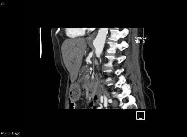
This diagnostic image is a contrast-enhanced sagittal CT scan of the abdomen, specifically focusing on the vascular anatomy and the vertebral column. The image demonstrates a rare anatomical variant where the superior mesenteric artery (SMA) originates from the celiac axis rather than directly from the abdominal aorta. A white arrow points to this common celiac-mesenteric trunk, showing the joint origin and the subsequent anterior descent of the SMA. Visible landmarks include the hyperdense vertebral bodies and intervertebral discs of the lumbar spine, the abdominal aorta running anterior to the spine, and portions of the liver and gastrointestinal tract with varying soft tissue densities. This clinical imaging is essential for preoperative surgical planning, particularly in pancreatic or hepatobiliary procedures, as the variant significantly alters the vascular supply to the midgut. The educational focus is on identifying vascular anomalies and understanding their relationship to the central abdominal organs.
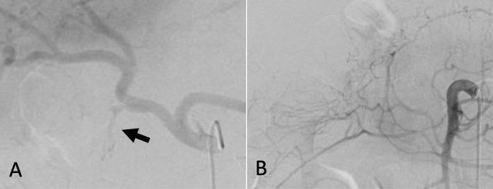
Two diagnostic angiograms (a and b) demonstrating normal arterial anatomy of the upper gastrointestinal region. Image (a) is a selective celiac trunk angiogram showing the celiac artery and its major branches: the tortuous splenic artery extending to the left and the hepatic artery giving rise to the gastroduodenal artery (GDA), indicated by a black arrow. Image (b) shows the superior mesenteric artery (SMA) and the origin of the inferior pancreaticoduodenal artery (IPDA). Both images demonstrate smooth arterial contours with uniform contrast opacification. There are no visual signs of vascular pathology, such as pseudoaneurysms, arterial stenosis, or active contrast extravasation (hemorrhage). This set of images serves as a clinical reference for normal mesenteric and celiac vasculature in the context of screening for postoperative complications like visceral artery pseudoaneurysms.
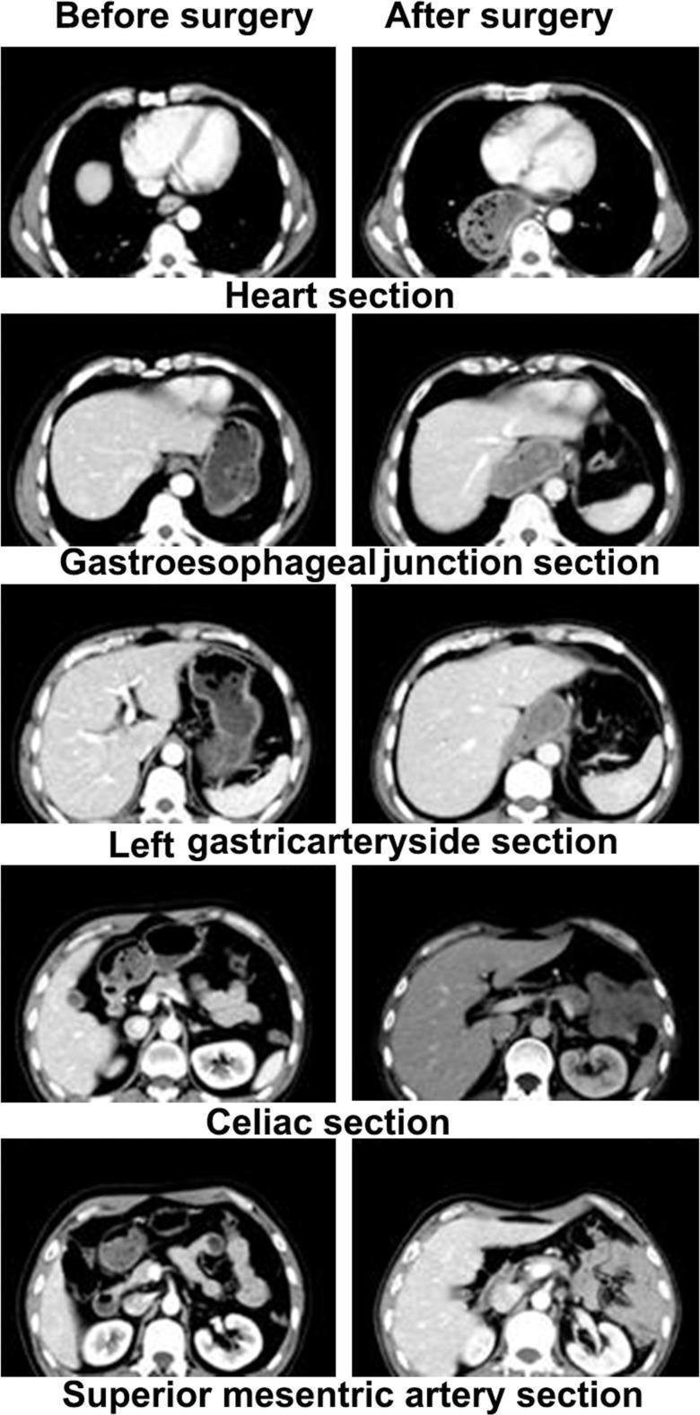
This diagnostic image comprises a series of axial contrast-enhanced CT scans comparing anatomical structures before and after radical surgery for esophageal cancer. The images are organized into five anatomical levels: the heart section, gastroesophageal junction section, left gastric artery side section, celiac section, and superior mesenteric artery section. The 'before surgery' column displays normal mediastinal and upper abdominal anatomy, including the esophagus and stomach in their typical positions. The 'after surgery' column demonstrates significant postoperative anatomical remodeling of the inferior mediastinum and epigastrium. Key changes include the transposition of a gastric conduit into the mediastinum (pull-up), causing a shift in heart and lung position at the thoracic level. At the abdominal levels, there is a notable loss of definition and displacement of vascular landmarks, such as the celiac artery and superior mesenteric artery, often obscured by transposed gastrointestinal tissue. These images illustrate the challenges in postoperative radiotherapy planning, as surgical distortion can shift high-risk lymph node stations (e.g., para-aortic and celiac groups) relative to their preoperative anatomical markers.
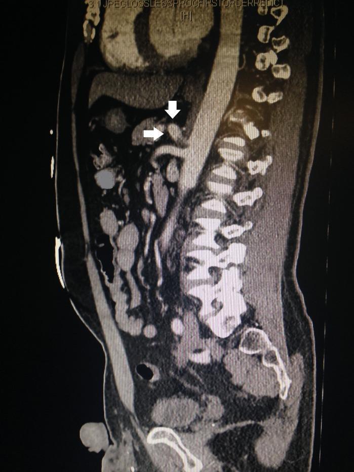
This diagnostic image is a contrast-enhanced computed tomography (CT) scan of the abdomen and pelvis in a sagittal reconstruction view. The image displays the lumbar spine posteriorly and the abdominal aorta as a hyperdense, vertically oriented vessel. A significant vascular pathology is identified at the origin of the celiac artery (ostium). White arrows indicate a focal dissection and associated pseudoaneurysm at the celiac axis. The pseudoaneurysm appears as a localized, irregular outpouching of contrast material protruding beyond the expected vessel wall boundary, with evidence of wall disruption. The superior mesenteric artery (SMA) is visible just inferior to the celiac artery origin. This imaging is critical for diagnosing mesenteric vascular emergencies and guiding conservative or surgical management in cases of isolated visceral artery dissection. The educational focus is on the radiological presentation of rare vascular abnormalities in the upper gastrointestinal arterial supply.
bile duct portal vein hepatic artery triangle of Calot
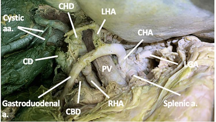
This clinical anatomical photograph displays a dissected hepatobiliary region and the celiac trunk branches in a cadaveric specimen. The image demonstrates the complex spatial relationships within the cystohepatic triangle (Calot's triangle). Centrally, the portal vein (PV) is visible, with the common hepatic artery (CHA) branching into the left hepatic artery (LHA) and gastroduodenal artery (a.). A significant anatomical variation is shown where the right hepatic artery (RHA) courses deep to the gastroduodenal artery and the common hepatic duct (CHD). The RHA is seen positioned between the portal vein and the common bile duct (CBD). Additionally, two cystic arteries (Cystic aa.) are identified originating from the RHA near the junction of the cystic duct (CD) and CHD. Other visible vascular structures include the splenic artery and the left gastric artery (LGA). This visual is intended for surgical education, specifically for understanding vascular and ductal variations during cholecystectomy or hepatobiliary surgery.
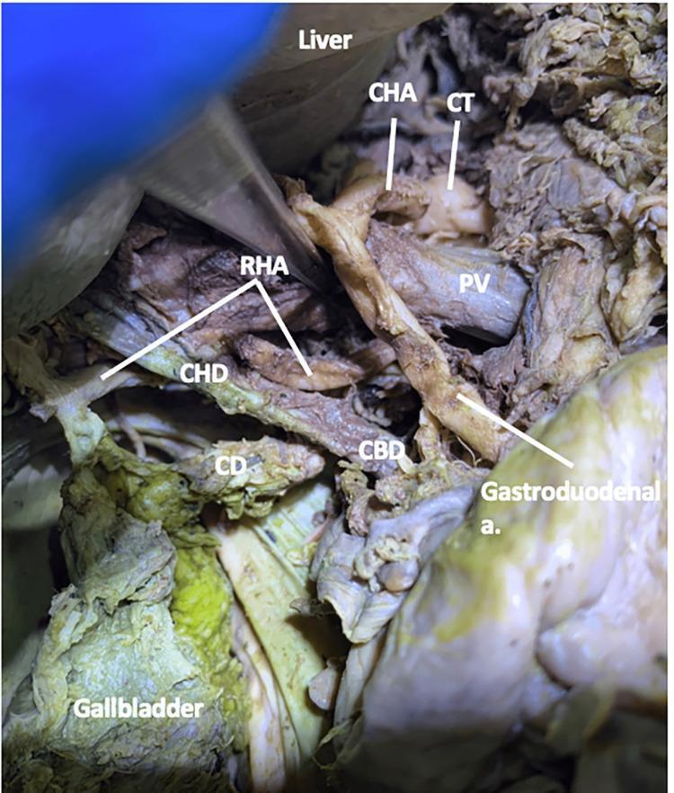
This clinical photograph from a gross anatomical dissection displays the hepatobiliary vasculature and biliary tree within the cystic triangle (Calot's triangle). The image illustrates a variation of the right hepatic artery (RHA), which is shown coursing between the portal vein (PV) and the common bile duct (CBD). Labeled structures include the liver (superiorly), gallbladder (inferiorly), cystic duct (CD), common hepatic duct (CHD), and common bile duct (CBD). The arterial supply is represented by the celiac trunk (CT), common hepatic artery (CHA), and the gastroduodenal artery. The educational focus of this image is to demonstrate the complex spatial relationships and anatomical variations of the hepatic artery in relation to the portal venous system and the extrahepatic biliary ducts, which is critical for surgical procedures like cholecystectomy. The RHA is seen moving laterally and anteriorly relative to the PV as it enters the cystic triangle to supply the gallbladder and right liver lobe.
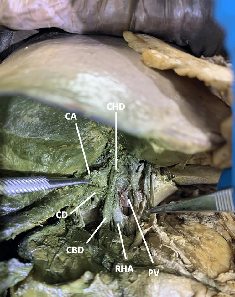
This clinical photograph displays a surgical dissection of the hepatobiliary region in a cadaveric specimen, illustrating the complex anatomy of the cystohepatic triangle (Calot's triangle). The image shows the liver retracted superiorly to reveal the portal triad and its branches. Key anatomical structures are labeled: the Right Hepatic Artery (RHA), Portal Vein (PV), Common Bile Duct (CBD), Common Hepatic Duct (CHD), Cystic Duct (CD), and Cystic Artery (CA). In this specific variation, the RHA follows a course between the PV and the CBD. Within the boundaries of the cystic triangle, a single CA is seen branching off the RHA to supply the gallbladder. Surgical forceps are visible, highlighting the dissection plane. This anatomical illustration serves as a reference for identifying vascular and biliary variations critical for preventing iatrogenic injury during cholecystectomy or hepatobiliary surgery. The educational focus is on the spatial relationships and variable branching patterns of the hepatic arterial system relative to the biliary tree.
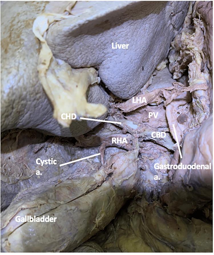
Anatomical dissection of the hepatobiliary region in a human cadaver, demonstrating the spatial relationships within the cystohepatic triangle (Calot's triangle). The image shows the right hepatic artery (RHA) coursing laterally toward the liver, where it gives rise to the cystic artery. The cystic artery is seen branching from the RHA and extending to the gallbladder wall. Key landmarks labeled include the liver (superiorly), gallbladder (inferiorly), common bile duct (CBD), and common hepatic duct (CHD). The portal vein (PV) is visible posterior to the arterial structures, while the left hepatic artery (LHA) and gastroduodenal artery are shown in their respective anatomical positions. This clinical photograph illustrates a standard anatomical configuration where the cystic artery originates from the RHA within the cystic triangle, a critical area for identification during cholecystectomy to avoid iatrogenic injury to the biliary tree or hepatic vasculature.
autonomic nerves pelvis rectal surgery preservation hypogastric
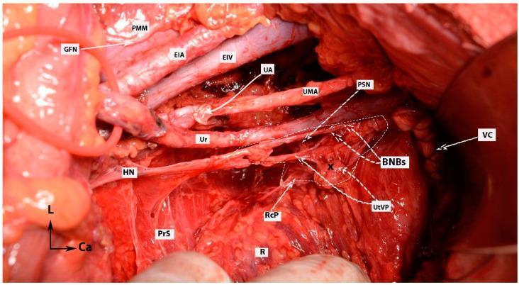
This clinical photograph provides a high-resolution surgical view of the pelvic retroperitoneal structures following a nerve-sparing radical hysterectomy. The image illustrates the complex neurovascular anatomy of the female pelvis, emphasizing the Inferior Hypogastric Plexus (IHP) and its branches. Major vascular landmarks include the external iliac artery (EIA) and vein (EIV) positioned superior-laterally, the umbilical artery (UMA), and the ligated uterine artery (UA). Critical neurological structures are meticulously exposed: the genitofemoral nerve (GFN) lies atop the psoas major muscle (PMM); the hypogastric nerve (HN) descends toward the presacral space (PrS); and the pelvic splanchnic nerves (PSN) contribute to the IHP. A primary educational focus is the preservation of the bladder nerve branches (BNBs), which are shown coursing toward the vaginal cuff (VC) and bladder base, lateral to the rectum (R) and the rectal plexus (RcP). The image demonstrates the anatomical relationships necessary for preserving autonomic function during oncological pelvic surgery, specifically identifying the distal ureter (Ur) and its proximity to the uterovaginal plexus (UtVP).
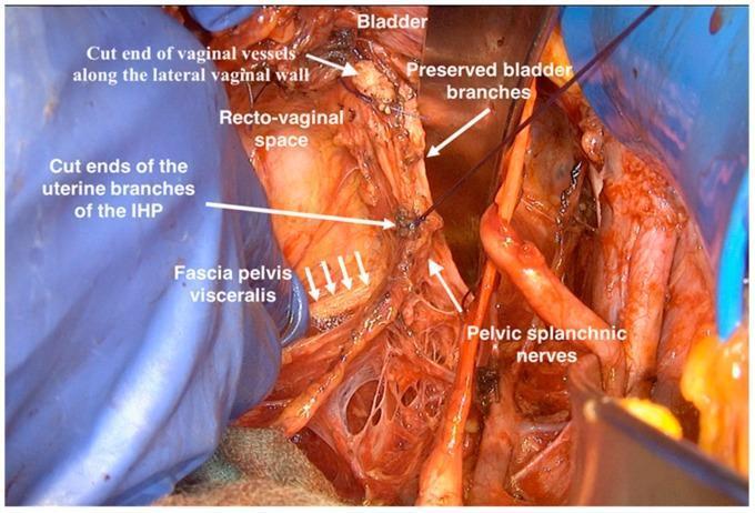
This clinical photograph captures an intraoperative view of a nerve-sparing radical hysterectomy, focusing on the dissection of the inferior hypogastric plexus (IHP) within the female pelvis. The image demonstrates the surgical preservation of autonomic neural structures following the resection of the uterus. Key anatomical landmarks and neurovascular structures are labeled: the bladder is visible superiorly, with preserved bladder branches of the IHP extending towards it. The recto-vaginal space is exposed, showing the cut ends of the vaginal vessels along the lateral vaginal wall. Inferior to these, the cut ends of the uterine branches of the IHP are identified. Deep to these structures, the fascia pelvis visceralis is highlighted by parallel arrows. On the lateral aspect, the pelvic splanchnic nerves are visible as cord-like structures emerging from the sacral roots. This visual serves as a critical educational resource for gynecologic oncology, illustrating the precise spatial relationships required to maintain pelvic autonomic function while achieving surgical margins in radical pelvic surgery.
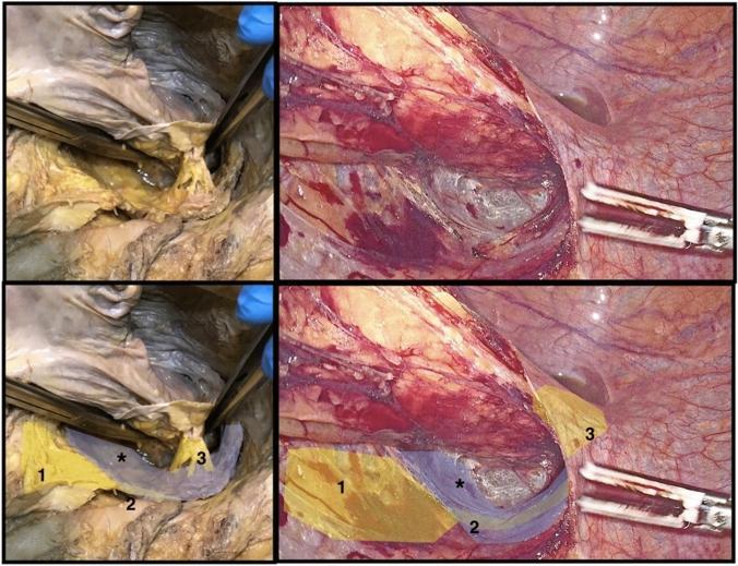
This composite image provides a side-by-side comparison of autonomic nerve structures in the human pelvis during cadaveric dissection (left) and laparoscopic surgery (right). The primary educational focus is the identification of key neural landmarks relevant to Total Mesorectal Excision (TME) to prevent post-operative dysfunction. Marked structures include: (1) the superior hypogastric plexus, appearing as yellowish connective tissue at the level of the promontory; (2) the hypogastric nerves, shaded in a dark bluish-grey, descending into the pelvis; and (3) the rectal nerves arising from the inferior hypogastric plexus, which are seen extending toward the posterolateral wall of the rectum. An asterisk (*) denotes the endopelvic or ureterohypogastric fascia, a critical surgical plane used to protect the hypogastric nerves during posterior and lateral dissection. The comparison demonstrates how these anatomical features transition from gross cadaveric tissue to their appearance under laparoscopic magnification and insufflation, emphasizing the importance of nerve-sparing techniques in colorectal surgery.
superior mesenteric artery branches small bowel anatomy diagram
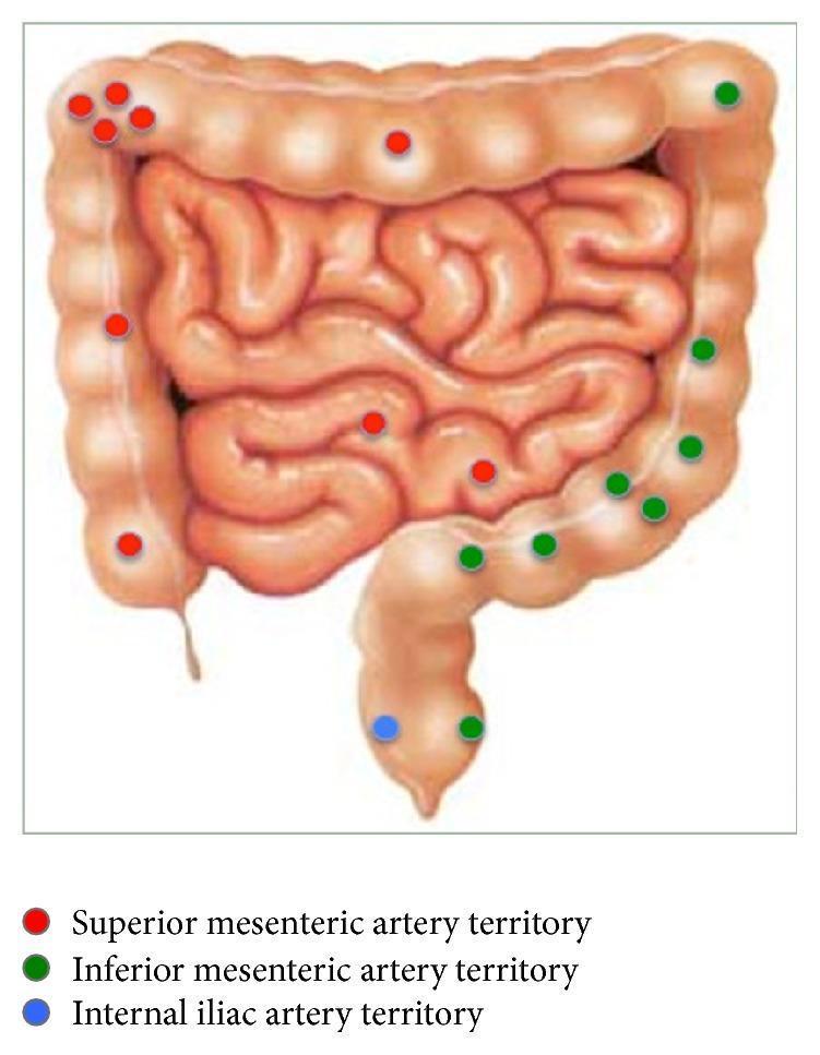
An anatomical diagram illustrating the distribution of gastrointestinal bleeding sites categorized by vascular territories. The diagram shows the large intestine (segmented haustra) and the small intestine (coiled loops) with superimposed colored markers. Red dots represent the superior mesenteric artery (SMA) territory, primarily involving the small intestine, cecum, ascending colon, and the proximal two-thirds of the transverse colon. Green dots indicate the inferior mesenteric artery (IMA) territory, covering the distal transverse colon, descending colon, and sigmoid colon. A single blue dot marks the internal iliac artery territory at the level of the rectum. The educational focus is on correlating anatomical bleeding locations with their respective arterial supply, which is critical for planning diagnostic interventions like angiography or embolization in cases of lower gastrointestinal hemorrhage. Key concepts include mesenteric vascular anatomy and clinical localization of bowel pathology.
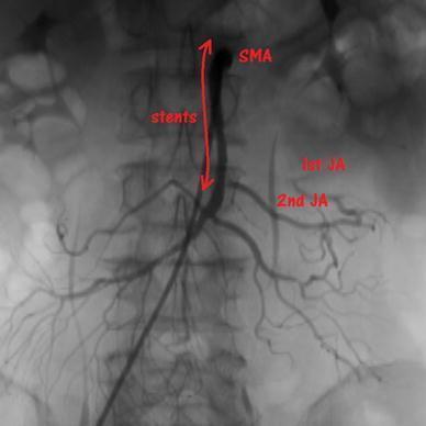
This diagnostic image is an abdominal angiogram (digital subtraction angiography) highlighting the mesenteric vasculature. The superior mesenteric artery (SMA) is the central vessel of interest, showing the placement of two endovascular stents extending from the proximal to the mid-portion of the artery. Red annotations and a double-headed arrow delineate the stented segment. Branching distally from the SMA, the first jejunal artery (1st JA) and second jejunal artery (2nd JA) are visible. The 2nd JA demonstrates robust contrast filling, whereas the 1st JA exhibits diminished perfusion in its distal marginal branches, suggesting localized ischemia or compromised flow despite SMA recanalization. The image illustrates the management of acute mesenteric ischemia (AMI) via thrombectomy and secondary stenting for atherosclerotic stenosis or thrombosis. The vascular anatomy is projected against the lumbar vertebrae, with bowel gas visible in the background. This visual serves as a clinical case for interventional radiology and vascular surgery, focusing on SMA stenting outcomes and collateral circulation patterns in the small intestine.
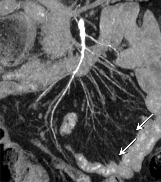
This diagnostic image is a coronal maximum intensity projection (MIP) MDCT reconstruction focusing on the abdominal arterial vasculature. The image demonstrates the superior mesenteric artery (SMA) and its distal branches in a patient with non-occlusive mesenteric ischemia (NOMI) secondary to hemorrhagic shock and vasopressor (VCA) support. Key findings include severe, diffuse vasoconstriction and luminal irregularity throughout the main trunk of the SMA. The secondary and tertiary branches, including the vasa recta, exhibit significant attenuation and a 'string-of-beads' or pruned appearance. Specifically, the white arrows highlight severe spasm of the distal mesenteric arcades, characterized by a marked reduction in vessel caliber and abrupt termination, indicating severely compromised peripheral vascular perfusion to the small bowel. This imaging represents a classic radiological presentation of drug-induced or shock-related mesenteric vasospasm, which clinically correlated with segmental ileal necrosis in this case.
Key Structures to Preserve During Gastrointestinal Surgery
1. VASCULAR STRUCTURES
A. Celiac Axis and its Branches
- Left gastric artery - supplies the lesser curvature of the stomach
- Common hepatic artery - divides into proper hepatic + gastroduodenal artery (GDA)
- Splenic artery - supplies the spleen, pancreatic body and tail, greater curvature of stomach
- Replaced/accessory right hepatic artery from the SMA (most common variant - 17%)
- Replaced/accessory left hepatic artery from the left gastric artery (13%)
B. Superior Mesenteric Artery (SMA)
- Entire small bowel
- Cecum, ascending colon, and proximal 2/3 of transverse colon
- Head of pancreas (via pancreaticoduodenal arcades)
| Branch | Territory |
|---|---|
| Jejunal/ileal arteries | Small intestine |
| Ileocolic artery | Terminal ileum + cecum |
| Right colic artery | Ascending colon |
| Middle colic artery | Transverse colon |
C. Inferior Mesenteric Artery (IMA)
- Left colic artery - descending colon / splenic flexure
- Sigmoid arteries
- Superior rectal (hemorrhoidal) artery - upper rectum
D. Portal Venous System
- Pancreatoduodenectomy: the SMV-portal vein confluence must be dissected carefully; it is the key vascular plane ("superior mesenteric vein groove")
- Hepatectomy: intrahepatic portal branches must be ligated segmentally to avoid compromising residual hepatic parenchyma
- Splenectomy: the splenic vein runs along the posterior pancreatic body and must not be avulsed - this risks hemorrhage and pancreatic injury
2. BILIARY STRUCTURES
Triangle of Calot (Cystohepatic Triangle)
- Inferior border of the liver (superiorly)
- Cystic duct (inferiorly/medially)
- Cystic artery (laterally)
- Common bile duct (CBD) - lies medial to the cystic duct; misidentification is the #1 cause of bile duct injury
- Right hepatic artery - courses through or near Calot's triangle in the majority of individuals; in ~14%, it forms a caterpillar hump
- Common hepatic duct
3. AUTONOMIC NERVES
A. Superior Hypogastric Plexus
- Low anterior resection
- Aortoiliac surgery
- Left colon mobilization
B. Hypogastric Nerves (L1-L2 sympathetics)
C. Pelvic Splanchnic Nerves (S2-S4, parasympathetics)
- Erection (men)
- Vaginal lubrication (women)
- Bladder detrusor contraction
D. Vagus Nerve (Anterior & Posterior Trunks)
4. UROLOGICAL STRUCTURES
A. Ureters
- Sigmoid colectomy - left ureter at the IMA root
- Right hemicolectomy - right ureter at the ileocolic vessel takeoff
- Low anterior resection - ureters near the lateral ligaments
- Hartmann's reversal - scarred planes obscure the left ureter
B. Bladder
5. FASCIAL PLANES AND TISSUE LAYERS
| Structure | Significance |
|---|---|
| Mesorectal fascia (fascial envelope of rectum) | Defines the TME plane; preserves pelvic nerves and maintains oncologic margin |
| Denonvilliers' fascia | Plane between rectum and prostate/vagina; anterior dissection plane in low rectal surgery |
| Gerota's fascia | Protects the kidney during right/left colon mobilization |
| Toldt's fascia (white line) | Avascular fusion plane for colon mobilization - stay in this plane to avoid duodenal or ureteric injury |
6. ORGAN-SPECIFIC SUMMARY TABLE
| Operation | Key Structure to Preserve | Consequence of Injury |
|---|---|---|
| Cholecystectomy | CBD, right hepatic artery | Bile leak, biliary stricture, hepatic ischemia |
| Whipple's procedure | Portal vein/SMV, GDA (if hepatic flow dependent), bile duct | Hemorrhage, hepatic ischemia |
| Gastrectomy | Aberrant hepatic arteries, vagal trunks | Hepatic ischemia, gastroparesis |
| Right hemicolectomy | Right ureter, SMA trunk, ileocolic vessels | Ureteric injury, bowel ischemia |
| Left hemicolectomy | Left ureter, IMA, marginal artery | Ureteric injury, ischemic anastomosis |
| Low anterior resection / TME | Pelvic splanchnic nerves, hypogastric nerves, ureters, middle rectal artery | Sexual dysfunction, urinary retention, anastomotic ischemia |
| Splenectomy | Splenic vein, pancreatic tail, left gastroepiploic artery | Pancreatitis, pancreatic fistula, gastric devascularization |
| Esophagectomy | Right gastroepiploic artery (gastric conduit), vagal trunks, thoracic duct, azygos vein | Conduit ischemia, chylothorax, gastroparesis |
- Identify before you ligate - every major vessel and the ureter must be positively identified
- Respect avascular planes (Toldt's line, mesorectal holy plane) - they separate structures without bleeding
- Protect the nerve plexuses during pelvic dissection - nerve-sparing TME is the standard of care

answer it according to uhs standard
"Identify key structures that must be preserved during gastrointestinal surgery."
key structures preserved gastrointestinal surgery ureter bile duct vagus nerve
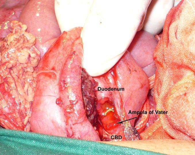
This clinical photograph captures an intraoperative view of the upper gastrointestinal and hepatobiliary systems during a surgical procedure. The operative field focuses on the duodenum and the extrahepatic biliary tract. Key anatomical structures are labeled, including the duodenum, the common bile duct (CBD), and the ampulla of Vater. The visual evidence shows a partial avulsion of the common bile duct near its insertion point at the duodenum. Clinical findings include significant tissue disruption, hematoma formation, and active bleeding in the periductal area, suggesting traumatic injury. The duodenum appears edematous and erythematous. A gloved hand is visible performing surgical retraction to expose the site of injury, and green surgical drapes border the inferior aspect of the field. This image serves as a clinical specimen illustration for hepatobiliary surgery, emergency trauma management, and the anatomical relationship between the biliary tree and the second part of the duodenum.

Two intraoperative clinical photographs (A and B) demonstrate key anatomical dissections during a nerve-sparing radical hysterectomy. Image A shows the transection of the vaginal vein (VV) and the medial mobilization of the uterine pedicle (UtP) to expose the ureteral tunnel. The ureter (Ur) is visible laterally as it courses toward the bladder. Image B illustrates the development of the 'Fourth space' (FS), a surgical avascular plane located between the ureter (Ur) and the vesicouterine ligament (VUL). Key vascular structures including the external iliac artery (EIA), external iliac vein (EIV), and umbilical artery (UMA) are identified. The vesical superficial vein (VSV) and vesicocervical vessels have been coagulated and transected. Notably, bladder nerve branches (NBs) are preserved, extending from the inferior hypogastric plexus toward the bladder (Bl). This educational material emphasizes surgical landmarks and planes necessary to prevent autonomic nerve injury during pelvic oncologic surgery.
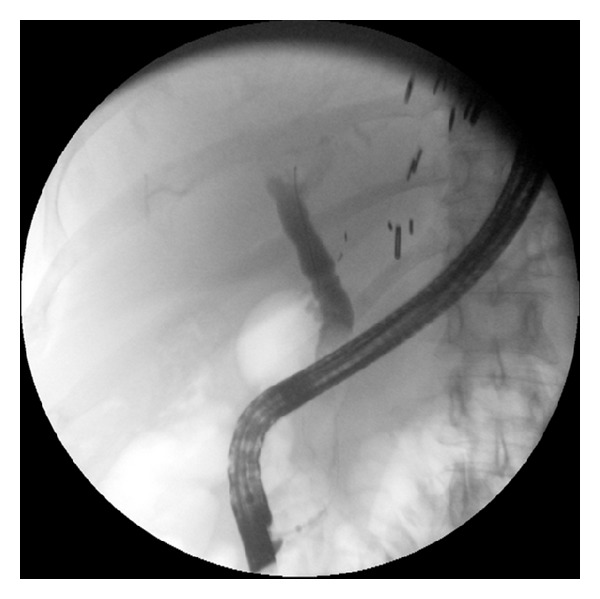
**Imaging Modality:** Fluoroscopic image obtained during Endoscopic Retrograde Cholangiopancreatography (ERCP). **Anatomical Region:** Upper gastrointestinal tract and biliary system, specifically the duodenum and common bile duct (CBD). **Key Landmarks and Devices:** A flexible, radiopaque side-viewing duodenoscope is positioned within the descending duodenum. Surgical clips are visible in the right upper quadrant, suggesting prior cholecystectomy or hepatobiliary surgery. The vertebral column is visible on the right aspect of the frame. **Observed Findings:** Opacification of the extrahepatic biliary tree is achieved via contrast injection. The common bile duct (CBD) demonstrates a patent lumen with a relatively uniform diameter. There is a notable absence of high-grade focal narrowing or filling defects within the visualized segment of the duct. Contrast flow appears to transit through the biliary system without significant obstruction. **Diagnostic Features:** The image illustrates the post-intervention state of the biliary tree, confirming the resolution of a previously documented biliary stricture. The caliber of the CBD is preserved, and there is no residual proximal ductal dilation visible in this view.
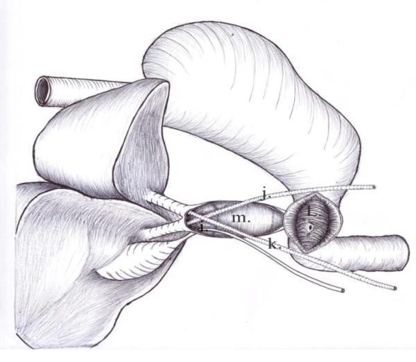
Anatomical diagram illustrating a biliary reconstruction procedure using a pedicled gastric tube. The illustration shows a longitudinal cross-section of the extrahepatic biliary system and the proximal gastrointestinal tract. Key structures are labeled: (i) represents a tube inserted into the gallbladder lumen; (j) and (k) denote stents or tubes placed within the right and left hepatic ducts, respectively. These tubes converge into (m), which is the interior of a pedicled gastric tube used as a conduit for biliary drainage. Structure (l) shows the interior of the duodenum with its characteristic mucosal folds (plicae circulares) and an anastomotic site where the gastric tube connects to the small intestine. The diagram emphasizes the surgical technique of using a gastric wall segment to bridge a common bile duct defect, facilitating passage from the hepatic ducts to the duodenum. This visual material is relevant for surgical oncology and hepatobiliary surgery education, demonstrating complex biliary tract reconstruction.
surgical anatomy abdomen gastrointestinal structures diagram
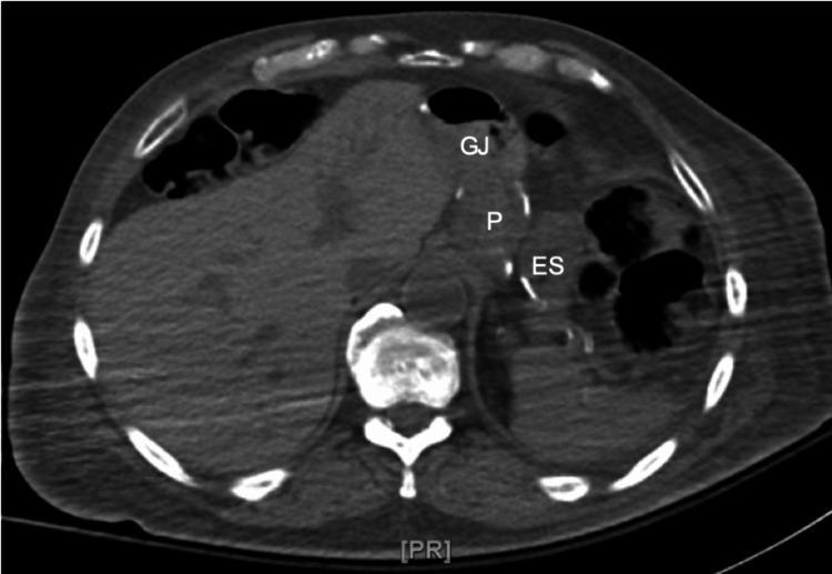
An axial computed tomography (CT) scan of the upper abdomen illustrating postoperative anatomy following Roux-en-Y gastric bypass (RYGB) surgery. The diagnostic image identifies three key gastrointestinal structures: the small gastric pouch (P), the excluded stomach (ES), and the gastrojejunal (GJ) anastomosis. The gastric pouch is visualized as a proximal, small-volume receptacle, separated laterally from the larger, defunctionalized excluded stomach (remnant stomach). The GJ anastomosis is located anteriorly, marking the surgical connection between the gastric pouch and the jejunal limb. Surrounding landmarks, including the liver, vertebrae, and ribs, provide anatomical orientation. This imaging is clinically relevant for evaluating postsurgical anatomy, identifying potential complications such as marginal ulcers or anastomotic leaks, and investigating metabolic symptoms like hyperinsulinemic hypoglycemia in bariatric patients.
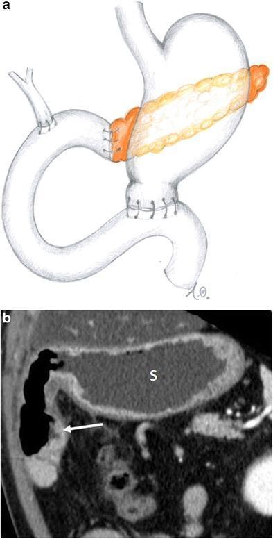
This figure illustrates the postoperative anatomy following a classic Whipple procedure (pancreaticoduodenectomy) through a comparative format. Part A is an anatomical diagram showing the reconstructed gastrointestinal tract, highlighting the gastrojejunostomy, hepaticojejunostomy, and pancreaticojejunostomy. The diagram emphasizes the resection of the pancreatic head, duodenum, and gallbladder with subsequent enteric anastomoses. Part B is a coronal CT image providing clinical correlation of these changes. In the CT scan, the stomach is labeled with an 's' and appears distended with low-attenuation fluid or contrast. A white arrow indicates the gastrojejunostomy, where the gastric antrum has been resected and the stomach is anastomosed to a jejunal loop. The imaging highlights the altered spatial relationships in the upper abdomen, specifically the positioning of the stomach and the efferent enteric loop. This material serves as an educational resource for identifying normal postoperative imaging findings and surgical landmarks after complex hepatobiliary surgery.
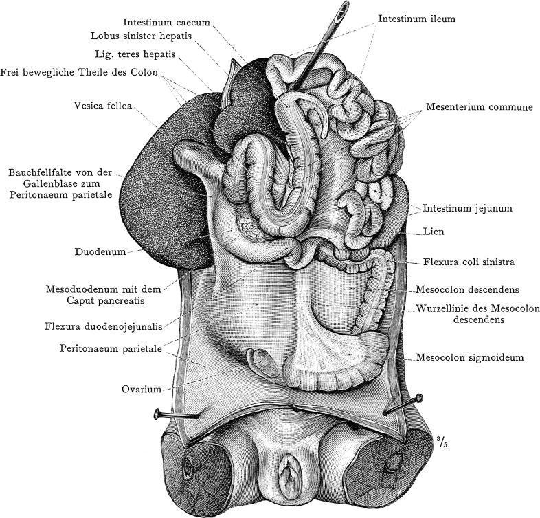
Historical anatomical diagram from Carl Toldt's 'Anatomischer Atlas' depicting a dissection of the human abdominal and pelvic cavity. The illustration focuses on the spatial relationships of the visceral organs and their peritoneal attachments. Key labeled structures include the spleen (Lien), shown as an oblong organ situated superior to the left colic flexure (Flexura coli sinistra) and adjacent to the jejunum. In the upper right quadrant (anatomical left), the left lobe of the liver (Lobus sinister hepatis), ligamentum teres, and gallbladder (Vesica fellea) are prominent. The gastrointestinal tract is shown with the duodenum, ileum, and cecum (Intestinum caecum). Extensive detail is provided on the mesentery and folds, including the Mesenterium commune, Mesocolon descendens, and Mesocolon sigmoideum. In the inferior pelvic region, the ovary (Ovarium) is visible. This diagram illustrates the complex organization of the peritoneum and the fixation of various abdominal organs, which is of historical and educational significance for understanding surgical anatomy and conditions such as 'wandering spleen' (splenoptosis).
recurrent laryngeal nerve esophagus thyroid surgery preserve
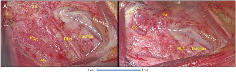
Two intraoperative clinical photographs (A and B) demonstrate the surgical dissection and settlement of the recurrent laryngeal nerve (RLN) during a thyroid procedure. Image A shows the anatomical relationship between the esophagus (ESO), trachea, and RLN within the expanded pretracheal space (Level VIa). The RLN is visualized running vertically in the tracheoesophageal groove, with the prevertebral fascia (PF) located posteriorly. Image B illustrates the completion of the RLN settlement. It features white dashed lines (α and β) marking critical surgical landmarks: Line α indicates the ligation of superior thyroid vessels with exposure of the cricothyroid space (CS) and preservation of the superior parathyroid gland, while Line β shows the resection plane where the thyroid gland (TG) was separated to expose the RLN's laryngeal entry point. The images highlight the surgical planes required for safe central neck dissection and preservation of neurovascular structures during endocrine surgery.
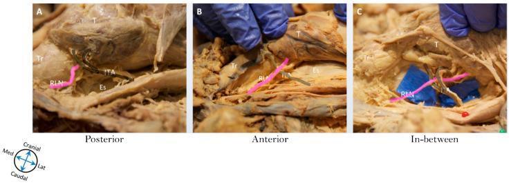
This clinical photograph sequence depicts anatomical dissections illustrating the surgical relationship between the recurrent laryngeal nerve (RLN) and the inferior thyroid artery (ITA), a critical landmark during thyroidectomy. The set consists of three panels labeled A, B, and C, with the RLN highlighted in pink for clarity. Panel A (Posterior) shows the RLN coursing posterior to the ITA trunk. Panel B (Anterior) shows the RLN crossing superficial (anterior) to the ITA. Panel C (In-between) demonstrates the nerve passing between the terminal branches of the ITA, with blue background material used to enhance visibility of the neural-vascular junction. Key surrounding anatomical structures labeled include the trachea (Tr), esophagus (Es), and thyroid gland (T). These images demonstrate anatomical variations essential for surgeons to identify to prevent iatrogenic nerve injury during endocrine neck surgery. The anatomical orientation is indicated by a directional compass showing cranial, caudal, medial, and lateral axes.
S2-018 | Surgical Anatomy
Key Structures That Must Be Preserved During Gastrointestinal Surgery
INTRODUCTION
- Blood vessels (arterial + venous)
- Biliary structures
- Neural structures
- Urological structures
- Fascial planes & ligaments
1. VASCULAR STRUCTURES
A. Arterial Supply - Must Not Be Compromised
Celiac Axis (T12 level) and Branches
| Branch | Structure Supplied | Surgery at Risk |
|---|---|---|
| Left gastric artery | Lesser curvature of stomach | Gastrectomy |
| Common hepatic artery | Liver, duodenum, bile duct | Whipple's, hepatectomy |
| Gastroduodenal artery (GDA) | Stomach, duodenum, pancreas | Pancreaticoduodenectomy |
| Splenic artery | Spleen, pancreatic body/tail | Splenectomy, distal pancreatectomy |
Important: In ~26% of patients, the right hepatic artery arises from the SMA (replaced/accessory). In ~13%, the left hepatic artery arises from the left gastric artery. These aberrant vessels must be identified before ligating the hepatoduodenal ligament or lesser omentum - division causes hepatic ischemia.
Superior Mesenteric Artery (SMA)
Inferior Mesenteric Artery (IMA)
Marginal Artery of Drummond
Middle and Inferior Rectal Arteries (from Internal Iliac)
B. Portal Venous System
- Portal vein (formed by SMV + splenic vein behind pancreatic head) - at risk in Whipple's procedure and hepatectomy
- Superior mesenteric vein (SMV) - the key vascular plane in pancreaticoduodenectomy
- Splenic vein - runs along posterior pancreatic body; avulsion during splenectomy causes torrential hemorrhage and pancreatitis
2. BILIARY STRUCTURES
Triangle of Calot (Cystohepatic Triangle)
- Inferior liver border (superior)
- Cystic duct (medial/inferior)
- Cystic artery (lateral)
| Structure | Consequence of Injury |
|---|---|
| Common bile duct (CBD) | Bile leak, biliary stricture, obstructive jaundice |
| Common hepatic duct (CHD) | Biliary obstruction |
| Right hepatic artery | Hepatic lobe ischemia |
The Critical View of Safety (CVS) must be established before any clipping - only two structures should be seen entering the gallbladder. Misidentification of the CBD as the cystic duct is the single most common cause of major bile duct injury.
3. NEURAL STRUCTURES
A. Vagus Nerve (Anterior and Posterior Trunks)
- Enter the abdomen through the esophageal hiatus
- Anterior trunk (mainly left vagus) lies on anterior surface of stomach
- Posterior trunk lies near the lesser curve/GEJ
- Injury during esophagectomy or fundoplication without pyloroplasty → delayed gastric emptying (gastroparesis)
B. Superior Hypogastric Plexus
- Located at the sacral promontory (L5-S1), anterior to aortic bifurcation
- Carries sympathetic fibres for ejaculation
- Injury → retrograde ejaculation, bladder dysfunction
- At risk during low anterior resection, left colonic mobilization
C. Hypogastric Nerves (L1-L2 sympathetics)
- Descend from superior hypogastric plexus bilaterally into the pelvis
- Injury → failure of seminal emission in males
D. Pelvic Splanchnic Nerves (S2-S4 - Parasympathetics)
- Run lateral to the rectum and join the Inferior Hypogastric Plexus (IHP)
- Control erection (males), vaginal lubrication (females), and bladder detrusor contraction
- Most commonly injured nerves during Total Mesorectal Excision (TME)
- Protected by dissecting in the correct mesorectal (holy) plane
4. UROLOGICAL STRUCTURES
A. Ureters
- Cross the common iliac arteries at the pelvic brim
- Run medial to gonadal vessels ("water flows under the bridge")
- Most commonly injured in:
- Left ureter → sigmoid colectomy (at IMA root), low anterior resection
- Right ureter → right hemicolectomy (at ileocolic vessel takeoff)
- Injury consequence: urinoma, ureteric fistula, hydronephrosis
- Prevention: always trace the ureter before vessel ligation; use ureteric stents in reoperative/pelvic cases
B. Urinary Bladder
- At risk during anterior rectal dissection and pelvic exenteration
- Must be mobilized carefully off Denonvilliers' fascia anteriorly
5. FASCIAL PLANES AND LIGAMENTS
| Structure | Location | Surgical Importance |
|---|---|---|
| Mesorectal fascia (fascia propria of rectum) | Envelope around the rectum | Defines the TME holy plane; protects pelvic nerves and maintains oncologic clearance |
| Denonvilliers' fascia | Between rectum and prostate/vagina | Anterior dissection plane in low rectal surgery |
| Waldeyer's fascia | Between rectum and lower sacrum | Posterior dissection plane; avoid penetrating it (risk of sacral venous plexus bleeding) |
| Toldt's fascia (white line of Toldt) | Lateral peritoneal reflection of colon | Avascular fusion plane for colon mobilization; staying in this plane avoids duodenal and ureteric injury |
| Hepatoduodenal ligament | Free edge of lesser omentum | Contains portal triad: CBD + hepatic artery + portal vein ("Pringle's manoeuvre" controls all hepatic inflow here) |
| Gerota's fascia | Around the kidney | Protect during right/left colon mobilization |
6. SUMMARY TABLE BY OPERATION
| Operation | Key Structures to Preserve | Consequence of Injury |
|---|---|---|
| Cholecystectomy | CBD, right hepatic artery, CHD | Bile leak, biliary stricture, hepatic ischemia |
| Whipple's procedure | Portal vein/SMV, GDA, CBD | Hemorrhage, hepatic ischemia, bile leak |
| Gastrectomy | Aberrant hepatic arteries, vagal trunks | Hepatic ischemia, gastroparesis |
| Right hemicolectomy | Right ureter, SMA trunk, ileocolic vessels | Ureteric injury, bowel ischemia |
| Left hemicolectomy | Left ureter, IMA, marginal artery | Ureteric injury, ischemic anastomosis |
| Low anterior resection / TME | Pelvic splanchnic nerves, hypogastric nerves, ureters, middle rectal artery | Sexual dysfunction, urinary retention, anastomotic ischemia |
| Splenectomy | Splenic vein, pancreatic tail | Pancreatitis, pancreatic fistula, hemorrhage |
| Esophagectomy | Right gastroepiploic artery (gastric conduit), vagal trunks, thoracic duct | Conduit ischemia, chylothorax, gastroparesis |
EXAM MNEMONICS FOR UHS
- V - Vessels (arterial supply + portal system)
- B - Bile duct (CBD, CHD)
- U - Ureters
- N - Nerves (vagus, sympathetic + parasympathetic pelvic plexuses)
- F - Fascial planes (TME plane, Toldt's line, Denonvilliers')
UHS Exam Tip: For a short-answer question, structure your answer as: (i) vascular structures, (ii) biliary structures, (iii) neural structures, (iv) urological structures. Always mention the specific surgery where each structure is at risk - this demonstrates applied clinical knowledge which UHS examiners reward with higher marks.
Generate a quick reference PDF comparing structures at risk in 8 major GI operations
ls -la /tmp/workspace/ 2>/dev/null || mkdir -p /tmp/workspace && echo "workspace ready"
mkdir -p /tmp/workspace/gi-surgery-pdf && python3 << 'PYEOF' from reportlab.lib.pagesizes import A4, landscape from reportlab.lib import colors from reportlab.lib.styles import getSampleStyleSheet, ParagraphStyle from reportlab.lib.units import mm, cm from reportlab.platypus import (SimpleDocTemplate, Table, TableStyle, Paragraph, Spacer, HRFlowable, KeepTogether) from reportlab.lib.enums import TA_CENTER, TA_LEFT, TA_JUSTIFY from reportlab.platypus import PageBreak import os OUTPUT = "/tmp/workspace/gi-surgery-pdf/GI_Surgery_Structures_At_Risk.pdf" # ── Page setup ────────────────────────────────────────────────────────────── doc = SimpleDocTemplate( OUTPUT, pagesize=landscape(A4), leftMargin=12*mm, rightMargin=12*mm, topMargin=14*mm, bottomMargin=14*mm, title="GI Surgery – Structures at Risk Quick Reference", author="UHS MBBS Year-5 | Surgical Anatomy S2-018", ) # ── Colour palette ─────────────────────────────────────────────────────────── C_DARK_TEAL = colors.HexColor("#0D4F6C") C_MID_TEAL = colors.HexColor("#1A7A9A") C_LIGHT_TEAL = colors.HexColor("#D6EFF7") C_GREEN_DARK = colors.HexColor("#1B6E3A") C_GREEN_MID = colors.HexColor("#2E9C56") C_GREEN_LIGHT = colors.HexColor("#D4F0DF") C_AMBER = colors.HexColor("#E8A020") C_AMBER_LIGHT = colors.HexColor("#FFF3D6") C_RED_DARK = colors.HexColor("#A0200A") C_RED_LIGHT = colors.HexColor("#FFE0DC") C_GREY_LIGHT = colors.HexColor("#F4F4F4") C_GREY_MID = colors.HexColor("#CCCCCC") C_WHITE = colors.white C_BLACK = colors.HexColor("#1A1A1A") # ── Styles ─────────────────────────────────────────────────────────────────── styles = getSampleStyleSheet() def PS(name, parent="Normal", **kwargs): return ParagraphStyle(name, parent=styles[parent], **kwargs) title_style = PS("TitleS", fontSize=18, textColor=C_WHITE, alignment=TA_CENTER, fontName="Helvetica-Bold", spaceAfter=2, leading=22) subtitle_style = PS("SubtitleS", fontSize=10, textColor=C_LIGHT_TEAL, alignment=TA_CENTER, fontName="Helvetica", spaceAfter=0, leading=14) section_hdr = PS("SecHdr", fontSize=9, textColor=C_WHITE, alignment=TA_CENTER, fontName="Helvetica-Bold", leading=12) cell_bold = PS("CellBold", fontSize=7.8, textColor=C_DARK_TEAL, fontName="Helvetica-Bold", leading=10, spaceAfter=1) cell_normal = PS("CellNorm", fontSize=7.4, textColor=C_BLACK, fontName="Helvetica", leading=9.5, spaceAfter=1) cell_red = PS("CellRed", fontSize=7.4, textColor=C_RED_DARK, fontName="Helvetica-Bold", leading=9.5) cell_green = PS("CellGreen",fontSize=7.4, textColor=C_GREEN_DARK, fontName="Helvetica-Bold", leading=9.5) legend_style= PS("LegS", fontSize=7.5, textColor=C_BLACK, fontName="Helvetica", leading=10) footer_style= PS("FootS", fontSize=6.5, textColor=colors.HexColor("#888888"), alignment=TA_CENTER, fontName="Helvetica-Oblique", leading=9) def B(text, style=cell_bold): return Paragraph(text, style) def N(text, style=cell_normal): return Paragraph(text, style) def R(text): return Paragraph(text, cell_red) def G(text): return Paragraph(text, cell_green) # ── Data ───────────────────────────────────────────────────────────────────── # Columns: Operation | Approach | Key Structures at Risk | Why at Risk | Consequence of Injury | Prevention data_raw = [ # (Operation, Approach, Key vessels, Key biliary/neural, Key other, Consequence, Prevention tip) ( "Laparoscopic\nCholecystectomy", "Laparoscopic\n(4-port)", "• Cystic artery\n• Right hepatic artery\n (caterpillar hump variant)", "• Common bile duct (CBD)\n• Common hepatic duct\n• Right hepatic duct", "–", "Bile leak / biliary stricture\nHepatic ischemia", "Critical View of Safety (CVS)\nbefore any clipping" ), ( "Whipple's\nProcedure\n(Pancreaticoduodenectomy)", "Open / Laparoscopic", "• Portal vein / SMV confluence\n• Gastroduodenal artery (GDA)\n• Replaced/accessory RHA\n (from SMA ~17%)", "• Common bile duct\n• Pancreatic duct", "• Duodenum (C-loop)\n• Common bile duct", "Hemorrhage (portal vein)\nHepatic ischemia (aberrant RHA)\nBile / pancreatic leak", "Identify SMV groove first.\nConfirm hepatic flow before\nligation of GDA." ), ( "Gastrectomy\n(Total / Subtotal)", "Open / Laparoscopic", "• Left gastric artery\n• Right gastro-epiploic artery\n• Aberrant left hepatic artery\n (from LGA ~13%)\n• Short gastric arteries", "• Vagus nerve (anterior\n & posterior trunks)\n• Thoracic duct (total)", "• Spleen (short gastrics)\n• Pancreatic tail", "Hepatic ischemia (aberrant LHA)\nGastroparesis (vagal injury)\nChylothorax (thoracic duct)", "Inspect lesser omentum for\naberrant LHA before ligation.\nPreserve vagal trunks unless\nintentional vagotomy." ), ( "Right\nHemicolectomy", "Open / Laparoscopic", "• SMA trunk (ileocolic,\n right colic, middle colic)\n• Marginal artery of Drummond", "–", "• Right ureter (at ileocolic\n vessel takeoff)\n• Duodenum (D2-D3)\n• Right gonadal vessels", "Small bowel ischemia (SMA)\nUreteric fistula / urinoma\nDuodenal injury", "Trace right ureter to pelvic brim.\nStay medial to gonadal vessels.\nIdentify D2 before ligating\nileocolic pedicle." ), ( "Left\nHemicolectomy", "Open / Laparoscopic", "• Inferior mesenteric artery (IMA)\n• Left colic artery\n• Marginal artery at\n splenic flexure", "–", "• Left ureter (at IMA root)\n• Left gonadal vessels\n• Superior hypogastric plexus", "Anastomotic ischemia\nLeft ureteric injury\nRetrograde ejaculation", "Identify left ureter at pelvic brim\nbefore IMA ligation.\nPreserve marginal artery." ), ( "Low Anterior\nResection / TME", "Open / Laparoscopic\n/ Robotic", "• Superior rectal artery (SRA)\n• Middle rectal artery\n (from int. iliac)\n• Inferior rectal artery", "• Superior hypogastric plexus\n (L5-S1, promontory)\n• Hypogastric nerves (L1-L2)\n• Pelvic splanchnic nerves\n S2-S4 (erigentes)\n• Inferior hypogastric plexus", "• Both ureters\n• Denonvilliers' fascia\n• Waldeyer's fascia\n• Bladder / prostate\n• Seminal vesicles", "Sexual dysfunction (nervi erigentes)\nRetrograde ejaculation\nUrinary retention\nAnastomotic ischemia", "Sharp dissection in mesorectal\n(holy) plane.\nIdentify both ureters at pelvic brim.\nPreserve pelvic autonomic plexuses." ), ( "Splenectomy", "Open / Laparoscopic", "• Splenic artery & vein\n• Short gastric arteries\n• Left gastro-epiploic artery", "–", "• Pancreatic tail\n (within 1 cm of hilum)\n• Left colon\n• Left hemidiaphragm", "Pancreatic fistula (tail injury)\nGastric devascularisation\nSubphrenic haematoma", "Dissect hilar vessels individually.\nIdentify pancreatic tail before\nstapling/clipping the hilum." ), ( "Esophagectomy\n(Ivor Lewis / McKeown)", "Thoracoscopic +\nLaparoscopic", "• Right gastroepiploic artery\n (gastric conduit supply)\n• Left gastric artery (divided)\n• Azygos vein", "• Thoracic duct\n• Recurrent laryngeal nerve\n (left > right)\n• Vagus nerve", "• Trachea / left mainstem\n bronchus\n• Aorta\n• Airway membranous wall", "Conduit ischemia / necrosis\nChylothorax (thoracic duct)\nHoarseness (RLN injury)\nAirway injury", "Preserve right gastroepiploic\narcade for conduit viability.\nIdentify RLN in tracheo-\nesophageal groove.\nLigate thoracic duct at aortic hiatus." ), ] # ── Column widths (landscape A4 = ~267mm usable) ───────────────────────────── PAGE_W = 267*mm col_widths = [32*mm, 22*mm, 52*mm, 48*mm, 42*mm, 38*mm, 46*mm] # Total = 280 - adjust proportionally scale = PAGE_W / sum(col_widths) col_widths = [w * scale for w in col_widths] # ── Build table rows ────────────────────────────────────────────────────────── HEADER_ROW = [ B("OPERATION", PS("H1", fontSize=8, textColor=C_WHITE, fontName="Helvetica-Bold", alignment=TA_CENTER, leading=11)), B("APPROACH", PS("H1", fontSize=8, textColor=C_WHITE, fontName="Helvetica-Bold", alignment=TA_CENTER, leading=11)), B("VASCULAR AT RISK", PS("H1", fontSize=8, textColor=C_WHITE, fontName="Helvetica-Bold", alignment=TA_CENTER, leading=11)), B("BILIARY / NEURAL", PS("H1", fontSize=8, textColor=C_WHITE, fontName="Helvetica-Bold", alignment=TA_CENTER, leading=11)), B("OTHER STRUCTURES", PS("H1", fontSize=8, textColor=C_WHITE, fontName="Helvetica-Bold", alignment=TA_CENTER, leading=11)), B("CONSEQUENCE\nOF INJURY",PS("H1",fontSize=8, textColor=C_WHITE, fontName="Helvetica-Bold", alignment=TA_CENTER, leading=11)), B("PREVENTION TIP", PS("H1", fontSize=8, textColor=C_WHITE, fontName="Helvetica-Bold", alignment=TA_CENTER, leading=11)), ] def make_row(idx, row): op, approach, vessels, biliary_neural, other, consequence, prevention = row bg = C_GREY_LIGHT if idx % 2 == 0 else C_WHITE return [ B(op, PS(f"OpS{idx}", fontSize=8.2, textColor=C_DARK_TEAL, fontName="Helvetica-Bold", leading=11, alignment=TA_CENTER)), N(approach, PS(f"ApS{idx}", fontSize=7.2, textColor=colors.HexColor("#444444"), leading=10, alignment=TA_CENTER)), N(vessels, PS(f"VsS{idx}", fontSize=7.4, textColor=C_DARK_TEAL, fontName="Helvetica-Bold", leading=10)), N(biliary_neural, PS(f"BnS{idx}", fontSize=7.4, textColor=C_GREEN_DARK, fontName="Helvetica-Bold", leading=10)), N(other, PS(f"OtS{idx}", fontSize=7.4, textColor=colors.HexColor("#555555"), leading=10)), N(consequence, PS(f"CqS{idx}", fontSize=7.4, textColor=C_RED_DARK, fontName="Helvetica-Bold", leading=10)), N(prevention, PS(f"PvS{idx}", fontSize=7.2, textColor=C_GREEN_DARK, leading=10)), ] table_data = [HEADER_ROW] + [make_row(i, r) for i, r in enumerate(data_raw)] # ── Table style ─────────────────────────────────────────────────────────────── row_colors = [] for i in range(1, len(table_data)): bg = C_GREY_LIGHT if i % 2 == 1 else C_WHITE row_colors.append(('BACKGROUND', (0, i), (-1, i), bg)) ts = TableStyle([ # Header ('BACKGROUND', (0, 0), (-1, 0), C_DARK_TEAL), ('ROWBACKGROUNDS',(0, 1), (-1, -1), [C_GREY_LIGHT, C_WHITE]), # Grid ('GRID', (0, 0), (-1, -1), 0.4, C_GREY_MID), ('LINEBELOW', (0, 0), (-1, 0), 1.5, C_MID_TEAL), # Alignment & padding ('VALIGN', (0, 0), (-1, -1), 'TOP'), ('ALIGN', (0, 0), (1, -1), 'CENTER'), ('TOPPADDING', (0, 0), (-1, -1), 4), ('BOTTOMPADDING', (0, 0), (-1, -1), 4), ('LEFTPADDING', (0, 0), (-1, -1), 5), ('RIGHTPADDING', (0, 0), (-1, -1), 5), # Alternating row shading via row_colors above ] + row_colors) main_table = Table(table_data, colWidths=col_widths, repeatRows=1) main_table.setStyle(ts) # ── Legend / footnote row ───────────────────────────────────────────────────── legend_data = [[ Paragraph("<b><font color='#0D4F6C'>■ Blue</font></b> = Vascular structures (arteries/veins)", legend_style), Paragraph("<b><font color='#1B6E3A'>■ Green</font></b> = Biliary / Neural structures", legend_style), Paragraph("<b><font color='#A0200A'>■ Red</font></b> = Consequence of injury", legend_style), Paragraph("TME = Total Mesorectal Excision | CVS = Critical View of Safety | RHA = Right Hepatic Artery | LGA = Left Gastric Artery | RLN = Recurrent Laryngeal Nerve", legend_style), ]] legend_table = Table(legend_data, colWidths=[54*mm, 54*mm, 54*mm, PAGE_W - 162*mm]) legend_table.setStyle(TableStyle([ ('BACKGROUND', (0,0),(-1,-1), colors.HexColor("#F0F8FF")), ('BOX', (0,0),(-1,-1), 0.5, C_MID_TEAL), ('VALIGN',(0,0),(-1,-1),'MIDDLE'), ('LEFTPADDING',(0,0),(-1,-1),6), ('TOPPADDING',(0,0),(-1,-1),4), ('BOTTOMPADDING',(0,0),(-1,-1),4), ])) # ── Title block ─────────────────────────────────────────────────────────────── title_data = [[ Paragraph("GASTROINTESTINAL SURGERY — STRUCTURES AT RISK", title_style), Paragraph("Quick Reference | UHS MBBS Year-5 | S2-018 Surgical Anatomy | Academic Year 2025-2026", subtitle_style), ]] title_table = Table([[ Paragraph("GASTROINTESTINAL SURGERY", title_style), ]], colWidths=[PAGE_W]) title_table.setStyle(TableStyle([ ('BACKGROUND', (0,0),(-1,-1), C_DARK_TEAL), ('TOPPADDING',(0,0),(-1,-1),8), ('BOTTOMPADDING',(0,0),(-1,-1),2), ])) subtitle_table = Table([[ Paragraph("Structures at Risk | Quick Reference | UHS MBBS Year-5 | S2-018 Surgical Anatomy | 2025-2026", subtitle_style), ]], colWidths=[PAGE_W]) subtitle_table.setStyle(TableStyle([ ('BACKGROUND', (0,0),(-1,-1), C_MID_TEAL), ('TOPPADDING',(0,0),(-1,-1),4), ('BOTTOMPADDING',(0,0),(-1,-1),6), ])) footer_para = Paragraph( "Sources: Bailey & Love's Short Practice of Surgery 28e | Yamada's Textbook of Gastroenterology 7e | Sabiston Textbook of Surgery | Fischer's Mastery of Surgery 8e", footer_style ) # ── Build story ─────────────────────────────────────────────────────────────── story = [ title_table, subtitle_table, Spacer(1, 4*mm), main_table, Spacer(1, 3*mm), legend_table, Spacer(1, 2*mm), footer_para, ] doc.build(story) print(f"PDF created: {OUTPUT}") print(f"File size: {os.path.getsize(OUTPUT):,} bytes") PYEOF
GI Surgery Structures At Risk
PDF Document · PDF
-
Landscape A4 format - optimised for quick scanning and printing
-
8 major GI operations covered in one reference table:
- Laparoscopic Cholecystectomy
- Whipple's Procedure (Pancreaticoduodenectomy)
- Gastrectomy (Total/Subtotal)
- Right Hemicolectomy
- Left Hemicolectomy
- Low Anterior Resection / TME
- Splenectomy
- Esophagectomy (Ivor Lewis / McKeown)
-
7 columns per operation:
- Approach used
- Vascular structures at risk (highlighted blue)
- Biliary / Neural structures (highlighted green)
- Other structures (ureter, duodenum, etc.)
- Consequence of injury (highlighted red)
- Prevention tip
-
Colour-coded rows for fast visual navigation
-
Legend bar explaining abbreviations (TME, CVS, RHA, RLN, LGA)
-
Source citations (Bailey & Love, Yamada, Sabiston, Fischer) at the bottom
-
UHS MBBS Year-5 branding (S2-018 Surgical Anatomy)