
boyle's anaesthesia, apparatus and other advanced anaesthesia machine
Reading File
The Boyle's machine is a continuous-flow anaesthesia apparatus with gas cylinders, pressure regulators, flowmeters (rotameters), vaporizers, a breathing circuit, and a rebreathing bag. Modern anaesthesia workstations add electronic monitoring, ventilators, and safety interlocks.
Searching sources...
Finding Sources
Finding Sources
Finding Sources
Finding Sources
Finding Sources
Finding Sources
Searching the Web
Boyle's anaesthesia machine components parts working principle detailed
Finding Sources
Reading Web Page
https://pmc.ncbi.nlm.nih.gov/articles/PMC3821260
Reading File
Reading File
Reading File
Reading File
I now have comprehensive information from Morgan & Mikhail's Clinical Anesthesiology and supplementary sources. Let me compile the full answer.
Loading Image
Here is a comprehensive, structured reference on Boyle's anaesthesia machine and advanced anaesthesia workstations, drawn from Morgan & Mikhail's Clinical Anesthesiology (7e), the PMC reference article on the basic anaesthesia machine, and Wikipedia's anaesthetic machine entry.
Boyle's Anaesthesia Machine - Complete Guide
1. Historical Background
- 1917 - Henry Boyle (British anaesthetist) modified a Gwathmey machine to create the first practical continuous-flow anaesthesia machine.
- 1921 - Waters introduced the to-and-fro CO2 absorption apparatus.
- 1927 - Flowmeter for CO2 included; the back bar appeared for the first time.
- 1930 - Circle absorption system introduced by Brian Sword.
- 1933 - Dry bobbin flowmeters introduced.
- 1952 - Pin Index Safety System (PISS) developed by Woodbridge.
- 1958 - Introduction of the Bodok seal.
- The modern anaesthetic workstation still retains all the key working principles of the original Boyle's machine.
2. Definition and Primary Functions
The Boyle's machine is a continuous-flow anaesthesia apparatus that:
- Receives high-pressure compressed gas from cylinders or pipeline supply.
- Creates a gas mixture of known composition and flow rate using flowmeters and vaporizer adjustment.
- Delivers this mixture continuously to the patient at a safe pressure and flow via the breathing circuit.
The full anaesthesia workstation adds to this: a ventilator, breathing system, waste anaesthetic gas disposal system (WAGDS), anaesthetic vapor delivery, monitoring devices, suction equipment, and optionally a drug delivery system.
3. Structural Framework
The machine is a continuous-flow apparatus mounted on a table. The body is made of box-shaped sections of welded steel or aluminium with:
- Wheels with antistatic tyres (castors) and brakes
- Antistatic measures (improve flowmeter performance; reduce ignition risk with flammable vapours)
- A back bar that supports the flowmeter assembly and vaporizers
- A common gas outlet (CGO) at the end of the back bar, to which breathing circuits attach
4. The Three Pressure Systems
The machine is divided into three pressure zones:
A. High Pressure System
- Receives gases directly at cylinder pressure (up to 1900 psig for O2)
- Contains: cylinder yokes, PISS, Bodok seals, pressure gauges, pressure regulators
- Reduces cylinder pressure to a stable 45-47 psig output
B. Intermediate Pressure System
- Receives gas from regulators (cylinders) or directly from pipeline (~50 psig)
- Delivers gas to: flowmeters, O2 flush valve, second-stage pressure reducers, ventilator drive
- Pipeline gases enter via DISS fittings (Diameter Index Safety System) - color-coded, non-interchangeable
- Cylinder gases enter via yoke assemblies with Pin Index Safety System (PISS)
C. Low Pressure System
- Takes gas from the flowmeters to the machine outlet
- Contains the vaporizers
- Operates at just above atmospheric pressure
5. Gas Supply Components
Cylinders
- E-cylinders attach to the machine via hanger-yoke assemblies
- Full E-cylinder: 600 L O2 at 1900 psig; 1590 L N2O at 745 psig
- Color coding (North America): O2 = green; N2O = blue; CO2 = gray; Air = yellow; He = brown; N2 = black
- (Colors differ by country - practitioners must verify local coding)
Pin Index Safety System (PISS)
- Prevents incorrect cylinder attachment
- Each gas has a unique pin arrangement on the yoke matching holes on the cylinder valve
- Yoke also contains: index pins, Bodok seal washer, gas filter, check valve (unidirectional flow)
Pipeline Supply
- O2, N2O, and air delivered via color-coded tubing from central hospital supply (~50 psig)
- Connected via DISS fittings - bore diameter is gas-specific, preventing wrong attachment
- A one-way check valve prevents retrograde flow into the pipeline
Pressure Regulators
- Reduce cylinder pressure to 45-47 psig (slightly below pipeline pressure of 50 psig)
- This ensures preferential use of pipeline supply when both are connected
- A high-pressure relief valve opens if supply pressure exceeds 95-110 psig (protects against regulator failure)
6. Flow Control System (Intermediate to Low Pressure)
Flow Control Knobs and Needle Valves
- Each gas has a dedicated knob controlling a needle valve that admits gas into the flowmeter
- Knobs are color-coded, have different sizes, and are touch-coded to prevent confusion
- O2 knob: larger, fluted, always on the right (by convention and safety standards)
Flowmeters (Rotameters)
- Variable-orifice, constant-pressure devices (rotameters)
- A tapered glass tube (Thorpe tube) with a float (bobbin/ball) - gas flow is read at the top of the float
- Higher flow = float rises higher
- O2 flowmeter is always last (closest to the vaporizer outlet) - ensures any leak in upstream tubing results in a hypoxic gas mixture escaping rather than reaching the patient
- Modern machines may have electronic flowmeters (no moving parts, more accurate)
Oxygen-Nitrous Oxide Proportioning Systems
- Prevents delivery of hypoxic mixtures
- Link-25 system (Ohmeda): a chain links N2O and O2 flow control sprockets - if N2O flow would cause FiO2 <25%, O2 flow is automatically increased
- Sensitive Oxygen Ratio Controller (SORC) (Dräger): a pneumatic resistor increases O2 flow or decreases N2O flow to maintain O2 ≥25%
- These systems cannot prevent hypoxia from O2 pipeline contamination or substitution - they only regulate the O2/N2O ratio
7. Vaporizers
Vaporizers convert liquid volatile anaesthetic into vapor and add it to the fresh gas flow at a precise, controllable concentration.
A. Copper Kettle (Historical - no longer clinical use)
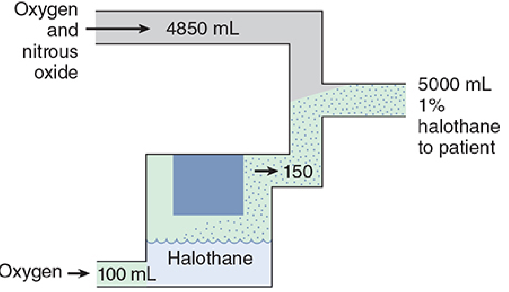
- A measured-flow vaporizer - carrier gas flow through liquid anaesthetic is controlled by a dedicated flowmeter
- All gas passes through the liquid and becomes saturated with vapor
- Saturated gas must be diluted before reaching the patient
- Example: 100 mL O2 through halothane kettle → 150 mL exits (32% halothane) → must dilute in 5 L total flow for 1% halothane
B. Modern Conventional Vaporizers (Variable Bypass / Plenum Vaporizers)
- Agent-specific and temperature-compensated
- Deliver a constant concentration regardless of temperature changes or fresh gas flow rate
- The fresh gas stream is split: a fraction (splitting ratio) passes through the vaporizing chamber, the rest bypasses it
- A bimetallic strip or wick mechanism adjusts the bypass ratio with temperature changes
- Examples: Tec series (Ohmeda), Vapor series (Dräger)
- Mounted on the back bar via Selectatec (Ohmeda) or Vapor lock (Dräger) systems
- Only one vaporizer can be active at a time (interlock prevents simultaneous opening)
C. Desflurane Vaporizer (Tec 6 / D-Vapor)
- Desflurane boils at 22.8°C at atmospheric pressure - standard variable bypass design would fail
- Uses a dual-circuit gas-vapor blender design
- The vaporizer heats desflurane to 39°C (vapor pressure ~1550 mmHg) and injects pure desflurane vapor into the fresh gas stream
- Requires electrical heating - cannot function without power
- Has a pressure-compensation mechanism for altitude changes
D. Drawover Vaporizers
- Gas is pulled through (drawn over) the liquid by patient's inspiratory effort - no pressurized gas supply needed
- Used in field anaesthesia, austere settings (e.g., Oxford Miniature Vaporizer, PAC vaporizer)
- Less precise than plenum vaporizers
8. The Back Bar and Common Gas Outlet
- The back bar is a horizontal manifold supporting vaporizers and connecting to the flowmeter assembly
- At the far end sits the Common Gas Outlet (CGO) - where all fresh gas exits the machine
- To the CGO attach: breathing circuits, WAGDS, reservoir bag
- An O2 flush valve is located here - delivers O2 at 35-75 L/min directly, bypassing flowmeters and vaporizers (used for emergencies but can cause barotrauma with certain breathing circuits)
9. Breathing Circuits
These carry gas from the machine to the patient and back.
A. Mapleson Circuits (Semi-open, no CO2 absorber)
| Circuit | Configuration | Best Use |
|---|---|---|
| Mapleson A (Magill) | APL valve near patient | Spontaneous ventilation |
| Mapleson D | APL valve near machine | Controlled ventilation |
| Mapleson F (Jackson-Rees) | Open-tail bag | Paediatric |
B. Circle System (Semi-closed/closed)
- Contains: two one-way valves, CO2 absorber canister, reservoir bag, APL valve, Y-piece
- CO2 absorber: soda lime (NaOH + Ca(OH)2 + KOH) or Baralyme
- Allows rebreathing of exhaled gas after CO2 removal → reduces waste and cost
- Fresh gas flow can be as low as 0.5 L/min (closed circuit)
- IMPORTANT: Trichloroethylene must NEVER be used with soda lime (produces neurotoxic dichloroacetylene)
C. Non-rebreathing Systems
- Jackson-Rees, Bain circuit, Ayres T-piece
- High fresh gas flows required
10. Safety Features
| Feature | Purpose |
|---|---|
| Pin Index Safety System (PISS) | Prevents wrong cylinder attachment |
| DISS fittings | Prevents wrong pipeline connection |
| Bodok seal | Gas-tight seal between cylinder and yoke |
| O2/N2O proportioning (Link-25, SORC) | Prevents FiO2 <25% |
| O2 failure warning alarm | Audible/visual alert on O2 pressure drop |
| O2 failure cutoff valve | Cuts N2O (and other gases) if O2 pressure falls |
| High-pressure relief valve | Opens if supply exceeds 95-110 psig |
| APL valve (pop-off valve) | Limits breathing circuit pressure; prevents barotrauma |
| Check valves | Prevent retrograde gas flow |
| Vaporizer interlock | Only one vaporizer can be open at a time |
| Color-coding | All knobs, cylinders, tubing color-coded by gas |
11. Waste Anaesthetic Gas Disposal System (WAGDS)
- Collects expired and excess anaesthetic gases vented from the APL valve and ventilator
- Prevents operating room contamination (chronic exposure linked to hepatotoxicity, reproductive toxicity)
- Types: active (vacuum-driven) and passive (relies on positive pressure)
- Must include a positive/negative pressure relief to protect the breathing circuit from hazardous pressures
12. Modern Anaesthesia Workstations
Advanced workstations (e.g., Dräger Perseus A500, GE Aisys CS2, Mindray A9) integrate:
- Electronic gas flow control - digital rotameters and displays
- Integrated ventilators - pressure-controlled, volume-controlled, pressure support, SIMV modes
- Built-in gas monitoring - capnography (EtCO2), agent analysis (infrared), O2 monitoring (paramagnetic or fuel cell)
- Electronic vaporizer systems (e.g., Dräger D-Vapor 3000)
- Integrated patient monitoring - SpO2, NIBP, ECG, temperature, NMT (neuromuscular transmission)
- Automated pre-use checkout - replaces much of the manual checklist
- Data recording and integration with anaesthesia information management systems (AIMS)
- Battery backup - rechargeable for brief power failures
- Standby mode for quicker power-up between cases
13. Anaesthesia Machine Checkout (Pre-Use Checklist)
Per the FDA/APSF recommendations and Morgan & Mikhail:
- Verify O2 cylinder pressure adequate (spare cylinder on machine)
- Check pipeline pressures (O2 ~50 psig, N2O ~50 psig)
- Check all flowmeters for smooth float movement
- Test O2 flush valve
- Test O2 failure alarm and cutoff systems
- Check vaporizers (filled, not tipped, caps on, Selectatec locked)
- Check breathing circuit integrity (leak test)
- Check CO2 absorber (color, granule state)
- Test APL valve and WAGDS
- Confirm ventilator function
- Confirm monitoring devices operational
- Verify suction working
14. Types of Anaesthesia Machines - Summary
| Type | Description | Use |
|---|---|---|
| Boyle's machine | Continuous-flow, rotameter-based, plenum vaporizers | Standard OR |
| Drawover apparatus | Patient's inspiration drives gas through vaporizer | Field/austere settings |
| Intermittent-flow (Entonox) | Demand-valve delivery of O2/N2O mix | Labour analgesia, dental |
| Total IV anaesthesia (TIVA) pump | No volatile agent - TCI propofol/remifentanil | Where inhalational avoided |
| Modern workstation | Fully integrated electronic system | Modern hospital ORs |
Sources:
- Morgan and Mikhail's Clinical Anesthesiology, 7e, Chapter 4 (Gas Supply, Flow Control, Vaporizers, Ventilators) - Morgan & Mikhail's Clinical Anesthesiology, pp. 113-132
- The Basic Anaesthesia Machine - Indian J Anaesth. 2013 (PMC3821260)
- Anaesthetic Machine - Wikipedia
This is a shared conversation. Sign in to Orris to start your own chat.