
Anastomosis in gluteal region and thigh
anastomosis gluteal region thigh arterial supply
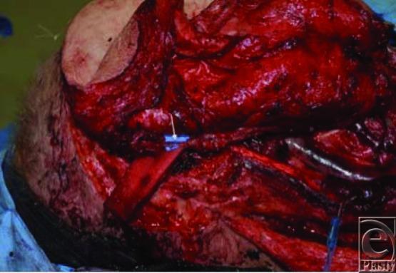
This clinical photograph displays an intraoperative view of a complex reconstructive microsurgery procedure in the head and neck region. The surgical field exhibits a near-total thigh free flap being integrated to cover a large cutaneous defect. Central to the image is a flow-through arterial anastomosis, indicated by a white arrow, where a blue microvascular coupler or connector joins the descending branch of the lateral circumflex artery to the facial artery. This specific configuration facilitates a sequential vascular pathway, allowing blood flow to travel through the facial artery into the lateral circumflex system and subsequently to a perforator from the profunda femoris artery. Multiple vascular structures and surgical sutures are visible within the highly vascularized, exposed tissue bed. The image serves as a clinical specimen illustration for plastic and reconstructive surgery, demonstrating advanced microvascular techniques for flap revascularization and the management of multiple independent arterial and venous pedicles.
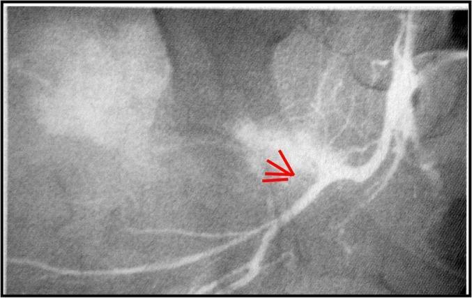
This diagnostic image is an angiogram of the pelvic region, focusing on the arterial supply to the gluteal area. The primary feature is a contrast-filled superior gluteal artery. Red arrows highlight a specific site of vascular damage characterized by contrast extravasation, indicating a vessel wall rupture or active hemorrhage. The normal smooth contour of the arterial trunk is interrupted by a focal area of irregular hyperdensity (contrast leakage) into the surrounding soft tissues. Anatomical landmarks include the trunk of the internal iliac artery and its posterior division branches. The surrounding musculature and pelvic bony structures are visible in the background with varying radiographic densities. This image demonstrates a traumatic vascular injury, likely secondary to a pelvic fracture, and serves as an educational example of how angiography is used to identify site-specific arterial bleeding in orthopedic trauma cases.
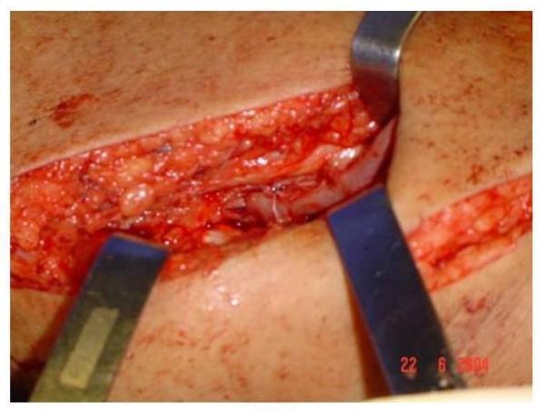
This clinical photograph shows an intraoperative view of a vascular surgery site, specifically an anastomosis between the saphenous vein and the superficial femoral artery (SFA). The surgical field is exposed via a longitudinal incision in the thigh, with metal retractors (Farabeuf or similar) providing retraction to reveal the subcutaneous fat and deeper vascular structures. The vessels appear reddish-pink, and the surgical site demonstrates standard vascularization with visible fine sutures, likely 6-0 polypropylene, at the anastomotic junction. The image illustrates the technical execution of an arteriovenous fistula (AVF) creation, where the saphenous vein is joined end-to-side to the superficial femoral artery. This procedure is typically performed for hemodialysis access in patients with suitable arterial and venous anatomy. The educational focus is on vascular dissection, exposure of the femoral vessels in the adductor canal region, and the precise placement of anastomotic sutures.
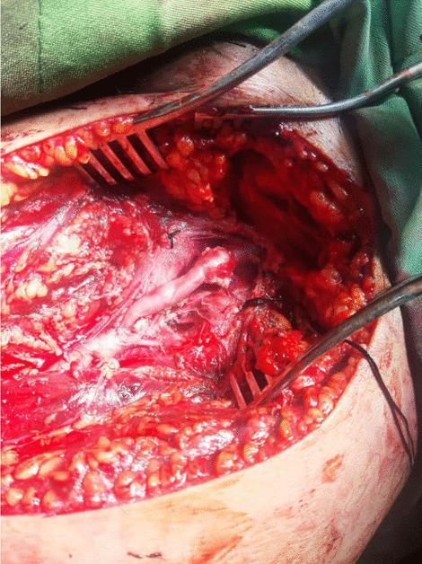
This clinical photograph captures an intraoperative view of a vascular reconstruction procedure. The image depicts a surgical field within the groin or thigh region, showing a longitudinal incision retracted by self-retaining and handheld metal retractors. The deep surgical site reveals an interposition saphenous vein graft used for a superficial femoral artery (SFA) repair. The graft is visible as a pale, glistening tubular structure bridging two arterial segments. The proximal and distal anastomoses are secured with fine, dark-colored monofilament sutures (likely Prolene), which appear to be applied in a continuous running fashion. The surrounding anatomy includes exposed muscle fibers, subcutaneous adipose tissue, and various levels of surgical hemostasis. The surgical field is moist and erythematous, consistent with an active open vascular procedure. This visual demonstrates the surgical management of a vascular injury, highlighting the technique of venous autograft interposition and arterial anastomosis in trauma or reconstructive surgery.
Anastomoses in the Gluteal Region and Thigh
1. Trochanteric Anastomosis
| Artery | Source |
|---|---|
| Superior gluteal artery | Internal iliac (posterior division) |
| Inferior gluteal artery | Internal iliac (anterior division) |
| Ascending branch of medial circumflex femoral artery (MCFA) | Profunda femoris |
| Ascending branch of lateral circumflex femoral artery (LCFA) | Profunda femoris |
| Deep circumflex iliac artery | External iliac |
- The MCFA, through its retinacular branches from this anastomosis, provides the majority of blood supply to the femoral head and neck.
- Disruption (e.g., femoral neck fracture, posterior hip dislocation) leads to avascular necrosis (AVN) of the femoral head.
2. Cruciate Anastomosis
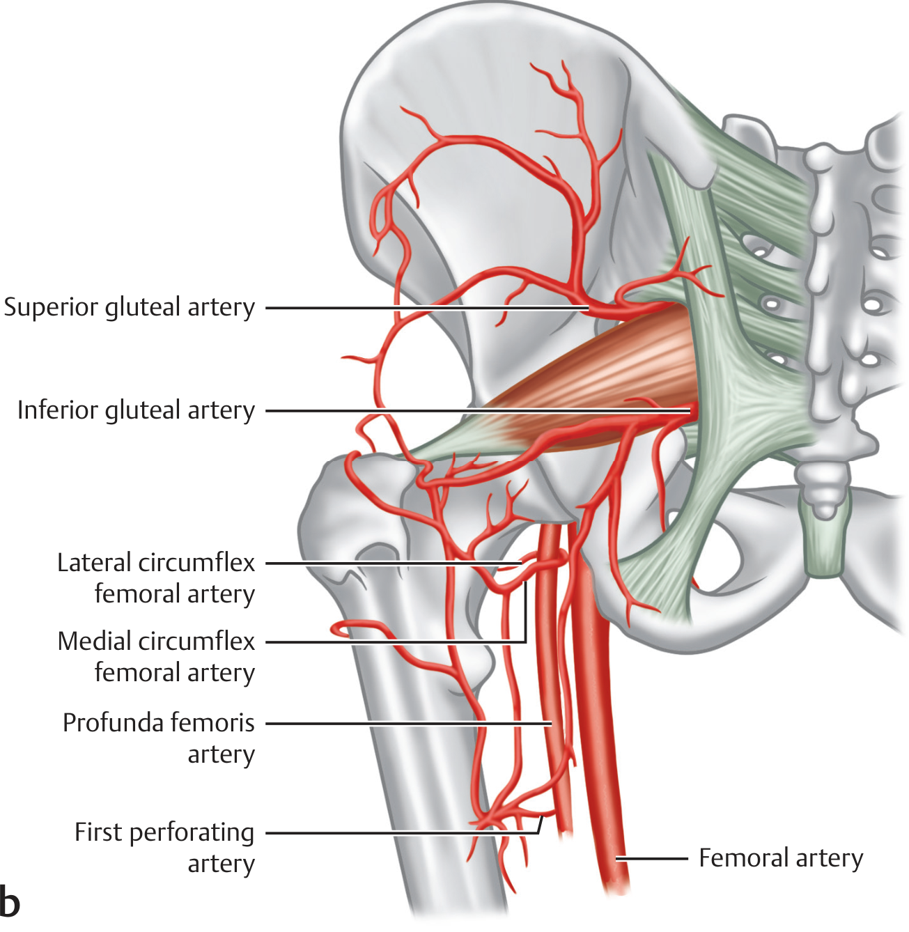
| Artery | Branch involved |
|---|---|
| Inferior gluteal artery | Descending branch |
| Medial circumflex femoral artery (MCFA) | Transverse branch |
| Lateral circumflex femoral artery (LCFA) | Transverse branch |
| First perforating branch of profunda femoris | Ascending branch |
- Acts as a major collateral pathway between the internal iliac circulation (inferior gluteal) and the profunda femoris (external iliac system).
- Becomes vital in external iliac artery or common femoral artery occlusion - blood reaches the thigh by retrograde flow through the inferior gluteal into the cruciate anastomosis and then down the profunda femoris.
Anatomical Diagram
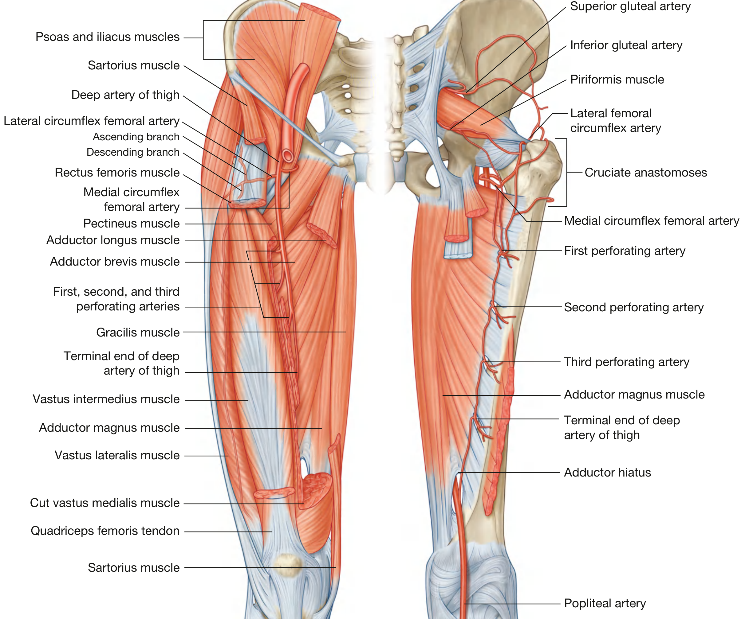
3. Other Important Anastomoses
Perforating Artery Chain (Longitudinal Anastomosis of the Thigh)
- The 3 (sometimes 4) perforating branches of the profunda femoris have ascending and descending branches that interconnect to form a longitudinal channel along the posterior compartment of the thigh.
- Superiorly, this chain participates in the cruciate anastomosis.
- Inferiorly, it participates in the genicular anastomosis around the knee.
Descending Branch of LCFA - Genicular Anastomosis
- The descending branch of the LCFA runs deep to rectus femoris, supplies vastus lateralis, and anastomoses inferiorly with the superior lateral genicular artery (from popliteal artery), linking the thigh to the knee anastomosis.
Corona Mortis ("Crown of Death")
- An anastomotic connection between the inferior epigastric artery (or external iliac) and the obturator artery, located behind the superior pubic ramus about 6 cm from the symphysis.
- Not a gluteal/thigh anastomosis per se, but clinically significant at the pelvic brim.
- At risk during anterior pelvic approaches; if injured, causes severe hemorrhage (hence the name).
Summary Table
| Anastomosis | Location | Vessels | Clinical Significance |
|---|---|---|---|
| Trochanteric | Trochanteric fossa | Superior gluteal, inferior gluteal, ascending MCFA, ascending LCFA, deep circumflex iliac | Femoral head blood supply; AVN if disrupted |
| Cruciate | Level of lesser trochanter | Inferior gluteal (desc.), transverse MCFA, transverse LCFA, 1st perforating (asc.) | Collateral: internal iliac ↔ profunda femoris; critical in femoral/iliac occlusion |
| Longitudinal perforating chain | Posterior thigh | 1st, 2nd, 3rd perforating arteries | Links cruciate to genicular anastomosis |
| Descending LCFA - genicular | Lateral thigh/knee | Descending LCFA + superior lateral genicular | Links thigh to knee collateral network |
| Corona mortis | Superior pubic ramus | Inferior epigastric ↔ obturator artery | Surgical hazard; pelvic approaches |
- Imaging Anatomy: Bones, Joints, Vessels and Nerves, Vol. 3 - Trochanteric and Cruciate Anastomosis sections
- Gray's Anatomy for Students - Lateral and medial circumflex femoral artery sections
- Miller's Review of Orthopaedics, 9th Ed - Cruciate anastomosis
- Fischer's Mastery of Surgery, 8th Ed - Arterial supply of the thigh
Show me trochanteric fossa in picture
trochanteric fossa femur anatomy
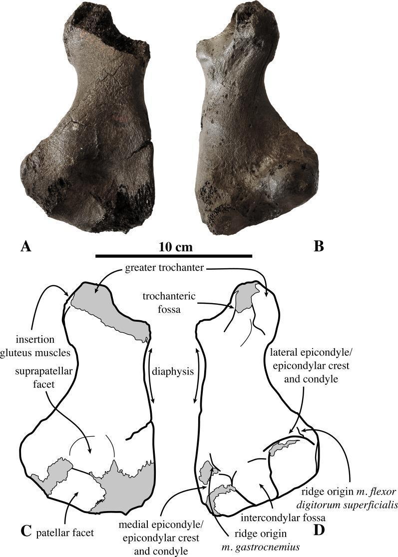
Comparative osteological study of a right femur from the fossil pinniped Prophoca rousseaui, presented in four panels (A-D). Panels A and B are high-resolution photographs of the fossilized specimen, while C and D provide corresponding anatomical line drawings with comprehensive labeling. The femur is depicted in anterior (A, C) and posterior (B, D) views. Key anatomical features identified include the proximal end with a prominent greater trochanter and trochanteric fossa, and a robust diaphysis (shaft). The distal portion demonstrates clear diagnostic features including the patellar and suprapatellar facets on the anterior surface, and the intercondylar fossa posteriorly. Muscle attachment sites are specifically indicated, such as the insertion for gluteus muscles and the origin ridges for m. gastrocnemius and m. flexor digitorum superficialis. Medial and lateral epicondyles/epicondylar crests are labeled at the distal extremity. A 10 cm scale bar is included for morphometric reference. This comparison serves as an educational tool for vertebrate paleontology and comparative anatomy, illustrating the morphology of early Phocinae.

**Imaging Modality:** Fluoroscopic Anteroposterior (AP) radiograph. **Anatomical Region:** Proximal femur and hip joint. **Observed Device/Pathology:** Antegrade intramedullary femoral nail (cephalomedullary nail) in situ. The image highlights the surgical entry point of the hardware relative to the proximal femoral anatomy. **Characteristic Visual Features:** * **Hardware:** A radiopaque intramedullary rod is positioned within the femoral canal. A transverse interlocking lag screw is visible, extending through the rod toward the femoral neck/head. * **Entry Point:** An arrow labeled "TROCHANTERIC" points to the proximal tip of the nail, demonstrating its insertion through the tip of the greater trochanter. * **Anatomical Landmark Comparison:** A second arrow and a vertical dashed line labeled "PYRIFORMIS FOSSA" indicate the traditional entry point medial to the greater trochanter. * **Nail Geometry:** The rod exhibits a lateral proximal bend (valgus offset) designed to accommodate the trochanteric entry point. **Clinical Context:** This image demonstrates the positioning of a trochanteric-entry nail, a design intended to preserve the medial soft tissues and vascularity associated with the piriformis fossa and femoral neck.
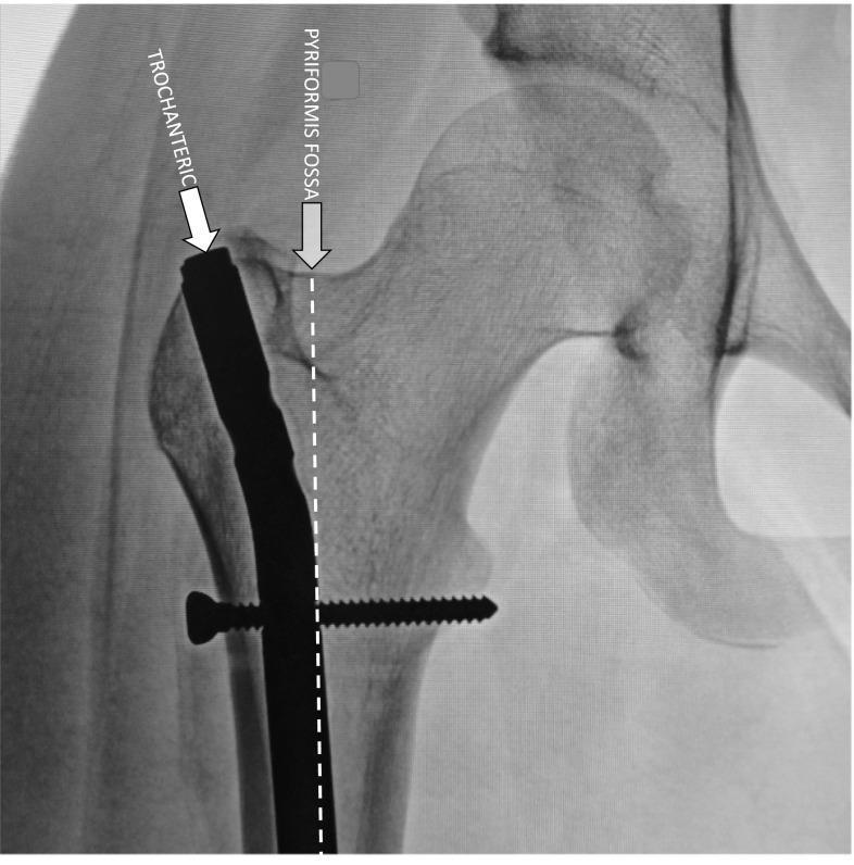
This diagnostic image is an anteroposterior (AP) X-ray radiograph of the proximal femur and hip joint, demonstrating the surgical placement of a modern trochanteric-entry antegrade intramedullary (IM) rod. The radiopaque metal rod is visible extending through the intramedullary canal of the femoral shaft. A key educational feature is the comparison of entry points: an arrow labeled 'TROCHANTERIC' points to the lateral tip of the greater trochanter where the rod enters, while a dotted vertical line and a second arrow labeled 'PYRIFORMIS FOSSA' indicate the traditional, more medial entry site. A proximal interlocking screw is seen traversing the rod horizontally through the femoral shaft below the lesser trochanter to provide rotational stability. This visual emphasizes the anatomical landmarks used in orthopedic surgery to mitigate risks of iatrogenic osseous necrosis by utilizing a trochanteric entry point, which maintains a safer distance from the circumflex vessels compared to the piriformis fossa entry.
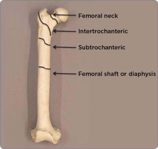
An anatomical diagram of a human femur bone, presented on a neutral background to illustrate common fracture sites and regional anatomy. The image identifies four primary proximal and mid-shaft regions using black labels and arrows. Starting from the proximal end, the 'Femoral neck' is indicated between the femoral head and the trochanters. Immediately distal to this is the 'Intertrochanteric' region, spanning the space between the greater and lesser trochanters. Below this lies the 'Subtrochanteric' region, representing the transition into the main body of the bone. Finally, the long, central portion is labeled as the 'Femoral shaft or diaphysis'. This illustration serves as an educational tool for medical professionals to classify orthopedic injuries, such as hip fractures or atypical femoral fractures (AFF), by precisely defining anatomical zones. The diagram emphasizes the proximal femur’s morphology, including the head, neck, and trochanteric areas, which are critical in radiology and surgical planning.
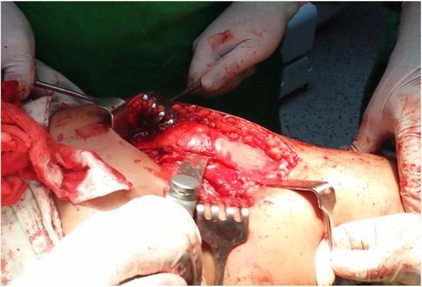
This clinical photograph captures an intraoperative view of a trochanteric osteotomy, a specialized orthopedic surgical procedure. The operative field is focused on the proximal femur and hip region, where deep surgical dissection has exposed the underlying musculoskeletal structures. Multiple surgical instruments are actively engaged in the field: several metallic retractors (including Hohmann and rake-type retractors) are strategically positioned to provide visualization by retracting the skin, subcutaneous fat, and muscle layers. An oscillating bone saw is visible in the center, applied to the cortical surface of the femur to perform the osteotomy. Visible anatomy includes the exposed femoral bone and surrounding vascularized muscle tissue. The clinical focus of this image is to demonstrate the surgical technique for trochanteric mobilization, often utilized in hip preservation surgery or complex arthroplasty to improve access to the hip joint while maintaining the continuity of the abductor mechanism. The procedure is relevant for orthopedic residents and surgeons studying hip reconstruction and surgical dislocation techniques.
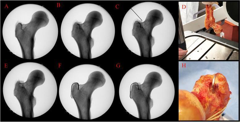
This composite figure consists of radiographic and clinical photographs investigating the anatomical origin of the radiographic lines on the proximal femur, specifically the medial greater trochanter. Images A and B are fluoroscopic views showing how femoral rotation (0° vs 30°) affects the alignment of the anterior and posterior trochanteric lines; at 0°, the lines are superimposed, while at 30°, they separate. Images C and D demonstrate a Kirschner wire (K-wire) placed in line with the posterior line, illustrating its physical anatomical landmark. Image E shows the disappearance of the anterior line following focal cortical bone removal at 30° rotation. Images F and G illustrate the reappearance of these lines when a radiopaque lead strip is placed in the surgical void at 0° and 30°, respectively. Clinical photographs D and H show the experimental setup of the cadaveric femur and the lead strip placement in the trochanteric fossa. This study is clinically relevant for orthopedic templating in total hip arthroplasty (THA), where precise femoral rotation is critical for accurate femoral offset measurement.
trochanteric fossa posterior femur greater trochanter medial surface anatomy diagram
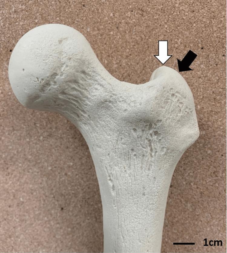
Anatomical Diagram: A high-resolution clinical photograph of a proximal human femur model, used to illustrate entry points for cephalomedullary (CM) nailing in orthopedic surgery. The image depicts the femoral head, femoral neck, and the greater trochanter. Two specific anatomical landmarks on the greater trochanter are identified with arrows: a white arrow points to the greater trochanteric tip (the most superior aspect), and a black arrow points to the 'bald spot' (a flattened or slightly depressed area on the posterior-lateral aspect of the trochanter). The bone surface exhibits natural-looking pits, ridges, and textures characteristic of cortical bone morphology. This visual is designed to assist orthopedic surgeons and residents in understanding optimal starting points for intramedullary nail insertion during the treatment of intertrochanteric fractures, highlighting the subtle differences in entry site location and their potential clinical implications.
Comparative osteological study of a right femur from the fossil pinniped Prophoca rousseaui, presented in four panels (A-D). Panels A and B are high-resolution photographs of the fossilized specimen, while C and D provide corresponding anatomical line drawings with comprehensive labeling. The femur is depicted in anterior (A, C) and posterior (B, D) views. Key anatomical features identified include the proximal end with a prominent greater trochanter and trochanteric fossa, and a robust diaphysis (shaft). The distal portion demonstrates clear diagnostic features including the patellar and suprapatellar facets on the anterior surface, and the intercondylar fossa posteriorly. Muscle attachment sites are specifically indicated, such as the insertion for gluteus muscles and the origin ridges for m. gastrocnemius and m. flexor digitorum superficialis. Medial and lateral epicondyles/epicondylar crests are labeled at the distal extremity. A 10 cm scale bar is included for morphometric reference. This comparison serves as an educational tool for vertebrate paleontology and comparative anatomy, illustrating the morphology of early Phocinae.
This composite figure consists of radiographic and clinical photographs investigating the anatomical origin of the radiographic lines on the proximal femur, specifically the medial greater trochanter. Images A and B are fluoroscopic views showing how femoral rotation (0° vs 30°) affects the alignment of the anterior and posterior trochanteric lines; at 0°, the lines are superimposed, while at 30°, they separate. Images C and D demonstrate a Kirschner wire (K-wire) placed in line with the posterior line, illustrating its physical anatomical landmark. Image E shows the disappearance of the anterior line following focal cortical bone removal at 30° rotation. Images F and G illustrate the reappearance of these lines when a radiopaque lead strip is placed in the surgical void at 0° and 30°, respectively. Clinical photographs D and H show the experimental setup of the cadaveric femur and the lead strip placement in the trochanteric fossa. This study is clinically relevant for orthopedic templating in total hip arthroplasty (THA), where precise femoral rotation is critical for accurate femoral offset measurement.
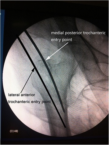
**Imaging Modality:** Intraoperative fluoroscopy (Anteroposterior radiograph). **Anatomical Region:** Proximal femur, specifically the greater trochanter and femoral neck. **Key Landmarks:** Greater trochanter apex, femoral shaft, and pelvic acetabulum (partially visible). **Observed Procedure/Clinical Context:** Comparison of surgical entry points for intramedullary nail or guide pin insertion during orthopedic hip surgery. The image features two superimposed guide pins or markers indicating distinct trajectories. **Characteristic Visual Features:** * **Lateral Anterior (LA) Entry Point:** A guide pin positioned 0.5 cm lateral to the apex of the greater trochanter. * **Medial Posterior (MP) Entry Point:** A guide pin positioned 0.5 mm medial to the apex on the medial edge of the greater trochanter. * **Visual Annotation:** White arrows and black text labels directly identify the "lateral anterior trochanteric entry point" and the "medial posterior trochanteric entry point." **Diagnostic/Differentiating Features:** The image demonstrates the spatial relationship between trochanteric anatomy and orthopedic instrumentation trajectories in the coronal plane. This visualization is critical for optimizing nail alignment and preventing iatrogenic fractures or malalignment during femoral fracture fixation.
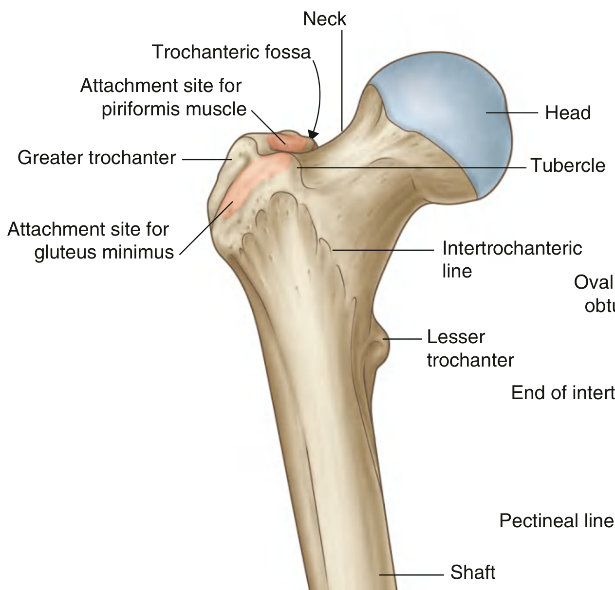
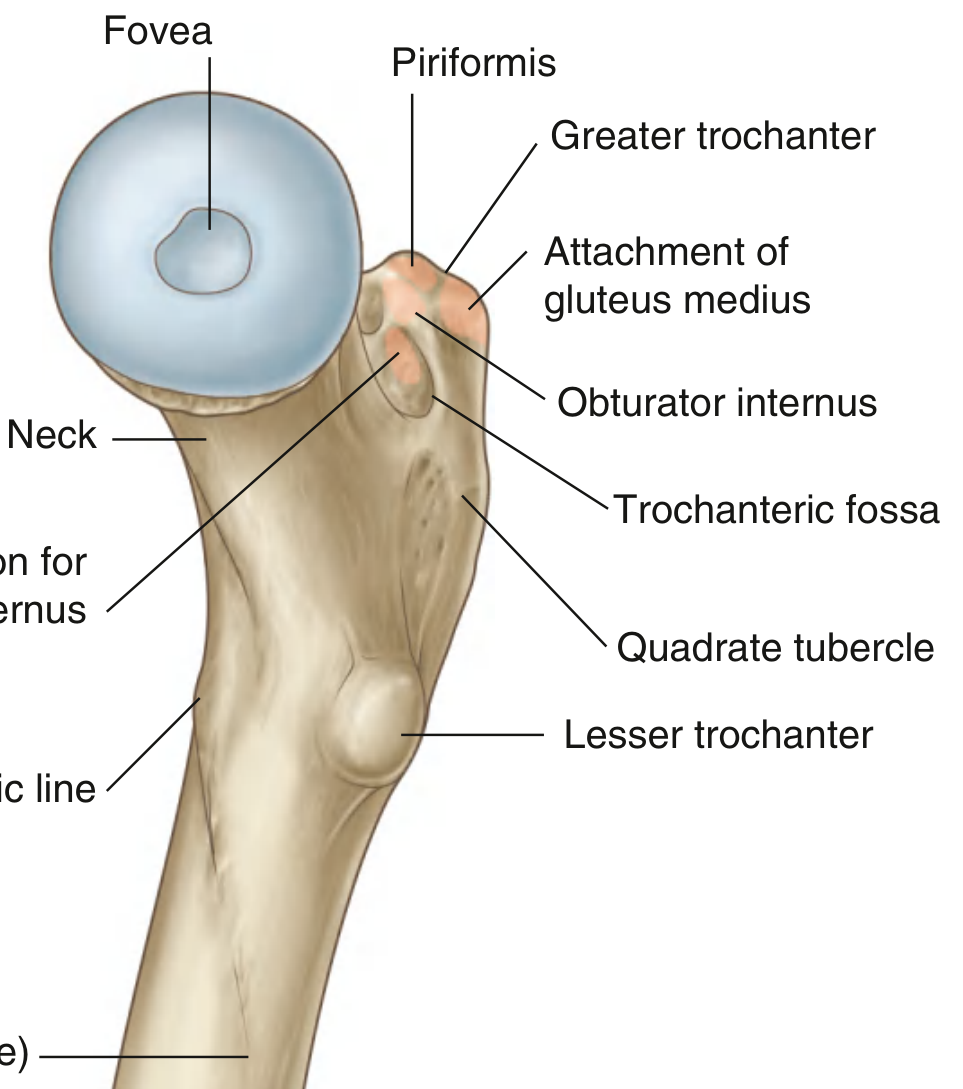
- It is a deep depression on the medial surface of the greater trochanter, visible best from the posterior view.
- The obturator externus tendon inserts into its lateral wall (the oval depression).
- Just above it, obturator internus + gemelli attach; and at the superior margin, piriformis attaches.
- This is also where the trochanteric anastomosis vessels (ascending MCFA, ascending LCFA, superior/inferior gluteal, deep circumflex iliac) converge to supply the femoral head via retinacular arteries.