
Muskeloskeletal tissue banking what's it usage indications methodology and advantages and disadvantages explain in detail with appropriate illustrative diagrams and images
musculoskeletal tissue banking indications methodology advantages disadvantages
https://nationalbloodtransfusion.co.uk/sites/default/files/e…
musculoskeletal tissue banking allograft
PMID: 36052382
musculoskeletal tissue bank types bone allograft processing sterilization freezing lyophilization orthopedic
https://pmc.ncbi.nlm.nih.gov/articles/PMC9385905
Musculoskeletal tissue banking workflow diagram showing the complete process: donor screening and consent, tissue procurement/recovery (bone, tendon, cartilage, ligament, meniscus), processing steps (cleaning/decontamination, sterilization, demineralization), preservation methods (fresh/refrigerated, deep freezing at -80°C, cryopreservation in liquid nitrogen, lyophilization/freeze-drying), quality testing and release, storage and inventory, clinical distribution to hospitals, and surgical implantation. Show tissue types collected including cortical bone, cancellous bone, femoral head, osteochondral grafts, tendons (patellar, Achilles), ligaments (ACL), meniscus. Include AATB accreditation logo. Medical educational diagram style with clear labels and arrows.
Medical diagram showing clinical indications for musculoskeletal tissue allografts in orthopedic surgery: ACL reconstruction with patellar tendon allograft, spinal fusion with femoral ring allograft, total knee revision with bulk bone allograft, tumor surgery with massive structural allograft, fracture non-union with cancellous bone graft, cartilage defect repair with osteochondral allograft, shoulder reconstruction with glenoid bone graft. Clean surgical anatomy illustration style with labels for each indication showing the graft placement site.
Musculoskeletal Tissue Banking (MSTB)
Overview
Workflow Diagram
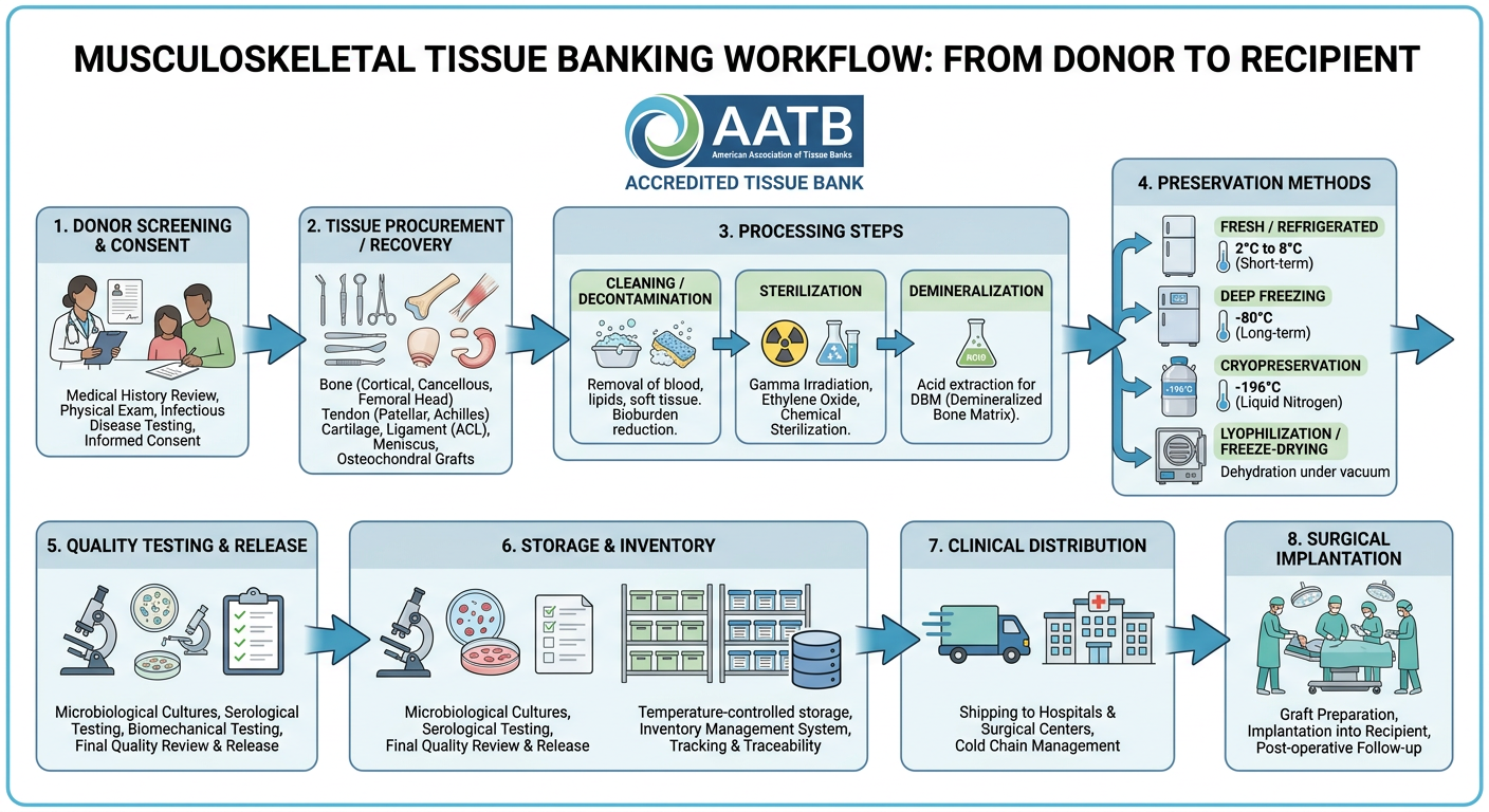
1. Types of Tissues Banked
| Tissue Category | Specific Examples |
|---|---|
| Cortical bone | Femoral shaft struts, tibial cortical grafts |
| Cancellous bone | Femoral head, iliac crest blocks, chips/morselized bone |
| Structural composite | Femoral rings, condylar allografts, whole femur/tibia |
| Demineralized Bone Matrix (DBM) | Putty, gel, strip - used as bone void filler |
| Osteochondral | Distal femur, proximal tibia, talar dome |
| Tendons | Patellar tendon, Achilles, quadriceps, tibialis anterior/posterior |
| Ligaments | ACL, PCL, collateral ligaments |
| Meniscus | Medial and lateral meniscal allografts |
| Fascia | Fascia lata |
| Skin | For burns (processed separately) |
2. Indications for Use
Clinical Indications
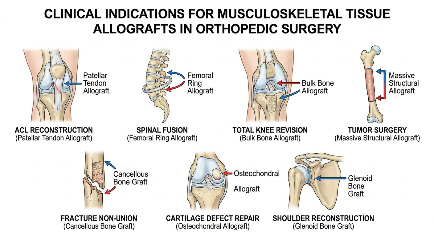
A. Bone Defects and Reconstruction
- Primary bone defects from tumor resection (limb salvage surgery) - massive structural allografts replace entire long bone segments
- Revision joint arthroplasty - when significant bone loss precludes adequate implant fixation (Campbell's Operative Orthopaedics, 15th Ed. 2026)
- Spinal fusion - femoral rings, fibular struts, and bone chips used as interbody spacers or to supplement autograft (Grainger & Allison's Diagnostic Radiology)
- Fracture nonunion and malunion - cortical strut allografts for periimplant fractures, cancellous chips for cavity filling
- Congenital skeletal dysplasias - corrective bone reconstruction
B. Soft Tissue Reconstruction
- Ligament reconstruction - ACL/PCL reconstruction using patellar tendon, Achilles, or tibialis anterior allografts (avoids donor site morbidity)
- Rotator cuff reconstruction - massive irreparable tears
- Patellar and quadriceps tendon repairs
- Shoulder instability - glenoid augmentation, subscapularis reconstruction
C. Cartilage Defects
- Osteochondral allograft transplantation (OCA) - large focal cartilage defects of knee, ankle, shoulder
- Meniscus allograft transplantation - post-meniscectomy syndrome in young patients with preserved alignment and stability
D. Special Scenarios
- Infection with massive bone loss - after debridement
- Radiation-damaged bone - reconstruction after oncologic resection
- Alveolar bone grafting in dental/maxillofacial surgery
- Periimplant fracture reconstruction
3. Methodology - Step-by-Step Process
Step 1: Donor Recruitment and Consent
- Referrals come from hospitals, coroners, and organ procurement organizations (OPOs)
- Consent is obtained from next-of-kin (deceased donors) or from the donor themselves (living donors - rare: surgical discard bone from elective procedures, femoral heads from hip arthroplasty)
- Time constraints: Tissue must be recovered within 48 hours of death (24 hours for eyes); refrigeration extends this window
Step 2: Donor Screening and Testing
- Cause of death, medical records, family/friend interview
- Exclusions: history of malignancy (except non-CNS primary), septicemia, systemic infection, prior organ transplant recipients, neurological disease of unknown etiology (CJD risk), chronic metabolic bone disease, significant trauma to the harvested tissue
- HIV-1/2 antibody + Nucleic Acid Testing (NAT)
- HCV antibody + NAT
- HBsAg, anti-HBc
- HTLV-I/II
- Syphilis (RPR/VDRL)
- CMV, EBV
- Trypanosoma cruzi (Chagas disease in endemic areas)
- West Nile Virus, Babesia
- Cultures taken at procurement
- Aerobic and anaerobic culture of tissue products before release
- Screen for history of trauma, metabolic bone disease (osteoporosis, Paget's disease), malignancy involving bone
Step 3: Tissue Procurement/Recovery
- Performed in sterile operating room conditions or approved recovery suite within the required time window
- Aseptic technique throughout (skin preparation, draping)
- Recovered segments are labeled, packaged in sterile bags, transported to the bank in appropriate temperature conditions
- Age limits apply for some tissues (e.g., osteochondral grafts preferably from donors <40 years for cartilage cell viability)
- Body reconstituted with prosthetics/filler after recovery to maintain dignity
Step 4: Processing
- Make tissue safer (decontamination/sterilization)
- Make it more clinically effective (e.g., decellularization, demineralization)
- Make it easier to store and transport (lyophilization)
- Debridement - removal of soft tissue, bone marrow, lipids, periosteum
- Physical cleaning - high-pressure water jets, pulsatile lavage, centrifugation, sonication
- Chemical cleaning - alcohol, hydrogen peroxide, detergents, antibiotic solutions
- Enzymatic digestion - removes cellular material (reduces immunogenicity)
- Demineralization (for DBM products) - acid extraction of mineral content, exposes bone morphogenetic proteins (BMPs) to enhance osteoinductivity
- Terminal sterilization (see below)
| Bank | System | Method |
|---|---|---|
| AlloSource | SterileR / Validated Sterilizer | Bioburden reduction + low-dose terminal irradiation |
| Lifenet | Allowash XG | Scrubbing, alcohol, antibiotics, H2O2 |
| RTI (Regeneration Tech.) | BioCleanse | Vacuum-pressure, low temperature, H2O2 + alcohol |
| MTF | Allograft Tissue Purification (ATP) | Non-ionic detergent, H2O2, alcohol, antibiotic cocktail |
| TBI | TranZgraft | Proprietary low-temperature sterilization |
Step 5: Terminal Sterilization
| Method | Mechanism | Advantages | Disadvantages |
|---|---|---|---|
| Gamma Irradiation | DNA strand breaks | Penetrates packaged tissue; no radioactive residue; gold standard | High doses (>50 kGy) weaken biomechanical properties of bone/collagen |
| Electron Beam Irradiation | Similar to gamma, less penetration | Faster processing | Less penetrating - good for thin grafts only |
| Ethylene Oxide (EtO) | Alkylates DNA | Effective sterilization | Toxic residue; long aeration time; may affect graft biology |
| Supercritical CO2 | Physical disruption of microbes | Low temperature - preserves biology | Cost; complex equipment |
| Plasma H2O2 | Oxidative killing | Low temperature, no toxic residue | Limited penetration |
Step 6: Preservation and Storage
| Method | Temperature | Shelf Life | Best For | Key Drawback |
|---|---|---|---|---|
| Fresh/Refrigerated | 1-10°C | Days to weeks | Osteochondral grafts (viable chondrocytes) | Complex logistics; very short shelf life |
| Deep Frozen | -40 to -80°C | 2-5 years | Structural bone, tendons, ligaments | Special freezer needed; thaw time |
| Cryopreserved | Liquid nitrogen (-196°C) or -80°C | Years | Meniscus (cell viability maintained) | LN2 tanks; high cost; shipping logistics |
| Freeze-dried (Lyophilized) | Ambient temperature | 5+ years | Cancellous bone, DBM, tendons, ligaments | Long rehydration time; altered biochemical properties |
| Glycerol/Alcohol preserved | Ambient | Months-years | Skin; some soft tissue | May never fully rehydrate; altered properties |
Step 7: Quality Control and Release Testing
- Final sterility cultures before release
- Dimensional measurements and labeling
- Biomechanical testing (for structural grafts)
- Tracking/chain of custody documentation
- Quarantine until all serology confirmed negative
- Living donor tissue: quarantined minimum 180 days, repeat serology to exclude "window period" infections (HIV, HCV NAT window: 9-11 days)
Step 8: Distribution and Implantation
- Grafts shipped to hospitals with full traceability documentation
- AATB-accredited banks maintain records allowing tracking from donor to recipient
- Surgeons must report adverse events to the tissue bank and FDA MedWatch system
4. Regulatory Framework
| Organization | Role |
|---|---|
| FDA (USA) | Regulates HCT/Ps (Human Cells, Tissues, Cellular and Tissue-Based Products); mandates Good Tissue Practices (GTP) |
| AATB (American Association of Tissue Banks) | Voluntary accreditation; sets processing standards since 1984 |
| EU Tissue Directive (2004/23/EC) | European mandatory licensing and inspection |
| NHSBT (UK) | National tissue banking via Human Tissue Authority licensing |
| State licensing | Many US states (NY, FL, CA, etc.) require additional licensure |
5. Advantages of Musculoskeletal Tissue Banking
Clinical Advantages
- No donor site morbidity - eliminates pain, fracture risk, and wound complications at iliac crest or fibula harvest sites (major benefit over autograft)
- Unlimited supply - not restricted by patient anatomy or size of autograft available
- Biomechanical similarity - properties closely approximate native human tissue
- Reduced operative time - no need to harvest graft separately; can reduce blood loss and anesthesia time
- Wide range of sizes/shapes - banked grafts available in custom dimensions for large defects impossible to reconstruct with autograft
- Massive reconstruction - tumor limb-salvage, revision arthroplasty with severe bone loss - scenarios where autograft simply cannot provide sufficient volume
- Osteoinductivity (DBM) - demineralized bone matrix releases BMPs and growth factors promoting bone healing
- Fresh osteochondral - only option providing viable chondrocytes for large cartilage defects
Logistic Advantages
- Lyophilized grafts can be stored at room temperature for years - easy inventory management
- Available "off the shelf" in a range of sizes, reducing surgical planning constraints
- Eliminates need for a second operative team harvesting autograft
6. Disadvantages of Musculoskeletal Tissue Banking
Disease Transmission Risk
- HIV, HCV, HBV, HTLV: Risk is extremely low with modern NAT testing (estimated ~1 in 1.6 million for HIV) but cannot be completely eliminated
- Bacterial contamination: Meta-analysis (Baseri et al., J Hosp Infect 2022, PMID 34752801) found contamination remains a clinically significant concern; clostridial infections have caused fatalities
- Emerging pathogens: Window period infections (SARS-CoV-2, West Nile, Chagas, Babesia) not always covered by standard testing
- CJD/prion disease: No reliable test exists; permanent exclusion criterion based on history
Biological/Mechanical Disadvantages
- Immunogenicity - allografts elicit an immune response; although generally subclinical, it may reduce incorporation and increase resorption risk
- No osteogenic cells - unlike autograft, processed allografts contain no living osteoblasts; purely osteoconductive/osteoinductive at best
- Reduced bone healing - autograft remains the gold standard with superior union rates, especially for critical-size defects
- Freeze-drying effects - lyophilization alters biochemical properties; graft may not fully rehydrate and biomechanical properties are somewhat reduced
- Graft failure/nonunion - structural allografts have higher nonunion rates and fracture risk compared to autograft or prosthetics in high-load situations
- Slow remodeling - large cortical allografts remodel very slowly (years); stress fracture is a long-term complication
Practical Disadvantages
- Cost - significantly more expensive than autograft; processed allografts carry substantial bank fees
- Availability - supply is limited by donation rates; specialized grafts (fresh osteochondral, size-matched meniscus) may have long wait times
- Ethical/religious concerns - some patients decline allograft on religious or personal grounds
- Complex logistics - cryopreserved grafts require specialized -80°C freezers or liquid nitrogen storage; shipping requires validated cold chain
- Regulatory burden - strict accreditation, tracking, and adverse event reporting requirements
- Rehydration time - lyophilized grafts require extended rehydration in the operating room before use
7. Comparison: Graft Options Summary
| Feature | Autograft | Allograft (Banked) | Prosthetic/Synthetic |
|---|---|---|---|
| Osteogenesis | Yes | No | No |
| Osteoinduction | Yes | Partial (DBM) | No |
| Osteoconduction | Yes | Yes | Partial |
| Disease transmission | None | Very low | None |
| Immune rejection | None | Low-moderate | Low |
| Donor site morbidity | Yes | None | None |
| Supply limit | Yes (patient anatomy) | Limited by donation | Unlimited |
| Cost | Low | Moderate-high | High |
| Evidence quality | Gold standard | Good | Variable |
| Large defects | Limited | Yes | Yes |
8. Historical Development
- 1942: First dedicated bone bank reported by Inclan
- 1950s: Regional bone bank concept emerged
- 1976: American Association of Tissue Banks (AATB) founded
- 1984: AATB issued first tissue processing standards
- 1986: AATB began formal accreditation program
- 1990s: HIV/HCV transmission cases prompted stricter screening
- 2004: EU Tissue and Cell Directive introduced mandatory licensing
- 2000s-present: NAT testing, terminal sterilization, proprietary processing, and lyophilization dramatically improved safety profile
- Today: >2 million MSK allografts used annually in USA alone
Key Points Summary
- Musculoskeletal tissue banking provides bone, cartilage, tendon, ligament, and meniscal allografts for orthopaedic reconstruction
- The process involves donor screening, aseptic procurement, multi-step processing (chemical + physical cleaning, sterilization, demineralization), preservation (fresh/frozen/lyophilized/cryopreserved), QC testing, and distribution
- Major indications: tumor limb salvage, revision arthroplasty, spinal fusion, ligament reconstruction, osteochondral repair, fracture management
- Gamma irradiation is the preferred terminal sterilization method; lyophilization allows ambient storage for years
- Key advantages: no donor site morbidity, unlimited sizes for massive defects, off-the-shelf availability, reduced operating time
- Key disadvantages: residual (very low) infection risk, no living cells, slower bone healing than autograft, high cost, immunogenicity
- Regulation by FDA, AATB (USA), EU Tissue Directive, and NHSBT (UK) ensures safety
- Henry's Clinical Diagnosis and Management by Laboratory Methods, 24th Ed. (Block 18, Tissue Banking chapter)
- Campbell's Operative Orthopaedics, 15th Ed. 2026 (Blocks 3, 30)
- AAOS Information Statement: Use of Musculoskeletal Tissue Allografts (AAOS 2020)
- Bagaria V et al., Indian J Orthop 2022, PMID 36052382 - Review of MSTB methodology
- Allograft Tissue Safety and Technology, PMC7151900
- Baseri N et al., J Hosp Infect 2022, PMID 34752801 - Systematic review: bacterial contamination of bone allografts
- NHSBT Tissue Banking: The Why and The How (2023)
Direct vertebral rotation indications contraindications procedure methodology advantages and disadvantages explain in detail with appropriate illustrative diagrams and images
direct vertebral rotation DVR scoliosis surgery indications contraindications procedure technique advantages disadvantages
"direct vertebral rotation" scoliosis pedicle screw
PMID: 38504001
direct vertebral rotation scoliosis Suk technique rod derotation comparison complications neurological risk
https://pmc.ncbi.nlm.nih.gov/articles/PMC5486624
Medical diagram showing direct vertebral rotation (DVR) technique in scoliosis surgery. Top panel: axial cross-section of thoracic vertebra with right thoracic scoliosis showing clockwise vertebral rotation, rib hump on right, and pedicle screws placed bilaterally. Middle panel: step-by-step sequence showing (a) precontoured concave rod placement, (b) rod derotation maneuver, (c) screw derotators attached to juxta-apical pedicle screws bilaterally, (d) counter-rotation applied via derotators to rotate vertebra back toward neutral - arrows showing direction of force applied convex and concave sides simultaneously. Bottom panel: before and after comparison showing vertebral axial rotation corrected from 25 degrees to 14 degrees, rib hump reduced. Clear medical illustration style with anatomical labels: apex vertebra, juxta-apical vertebra, concave side, convex side, screw derotator handles, rod.
Medical comparison diagram showing three scoliosis correction techniques side by side in axial view: (1) Simple Rod Derotation - rod rotated 90 degrees, vertebra poorly corrected, still rotated, rib hump remains; (2) Direct Vertebral Rotation DVR - bilateral screw derotators applied to pedicle screws, vertebra actively rotated back to neutral, rib hump significantly reduced, 42% correction; (3) Vertebral Coplanar Alignment VCA - alternative technique. Below: coronal X-ray comparison showing pre-op scoliosis curve Cobb angle 55 degrees vs post-op DVR correction to 12 degrees with 79.6% correction. Educational surgical technique comparison chart style with clear labels and arrows.
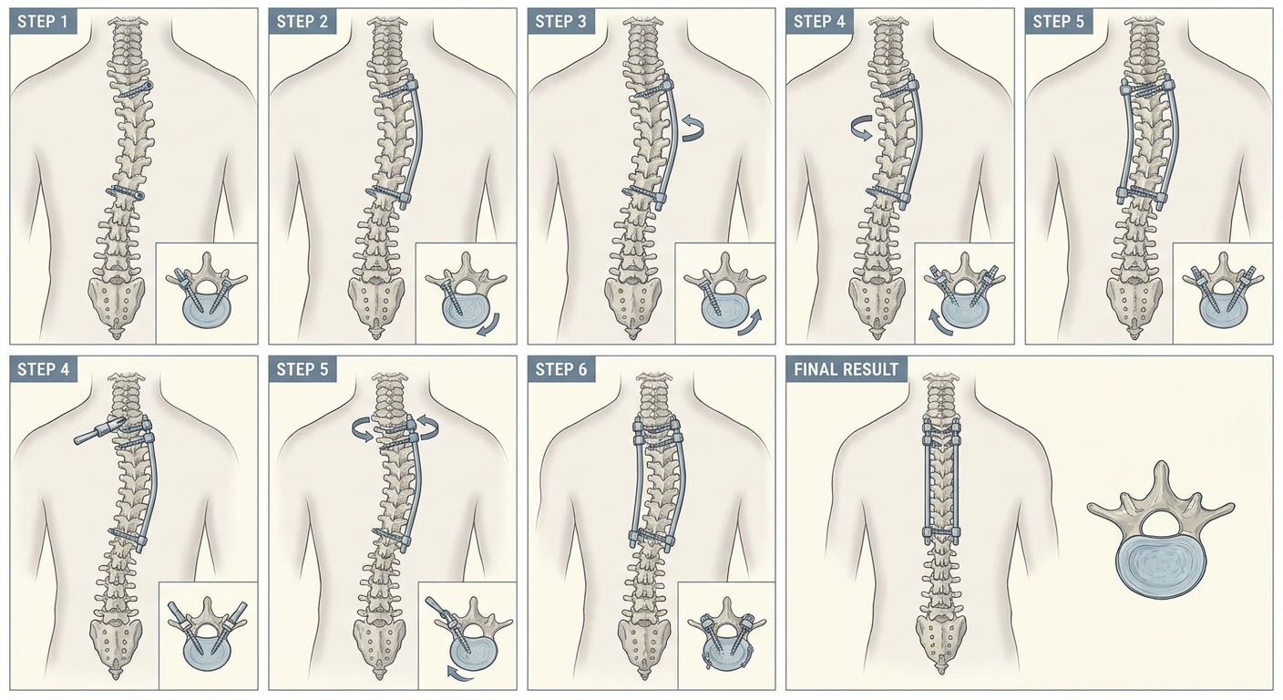
Step by step surgical technique illustration of direct vertebral rotation DVR for adolescent idiopathic scoliosis. Shows spine from posterior view and axial cross sections. Step 1: bilateral pedicle screws inserted at all fusion levels in right thoracic scoliosis. Step 2: concave rod contoured with extra kyphosis and placed into screws. Step 3: rod derotation performed counterclockwise. Step 4: screw derotators placed on juxta-apical and apical vertebrae both sides. Step 5: vertebrae rotated clockwise opposite to deformity using derotators simultaneously. Step 6: set screws tightened, second convex rod placed. Final result shows corrected spine alignment. Medical educational illustration.
Direct Vertebral Rotation (DVR) in Scoliosis Surgery
What is Direct Vertebral Rotation?
Illustrative Diagrams
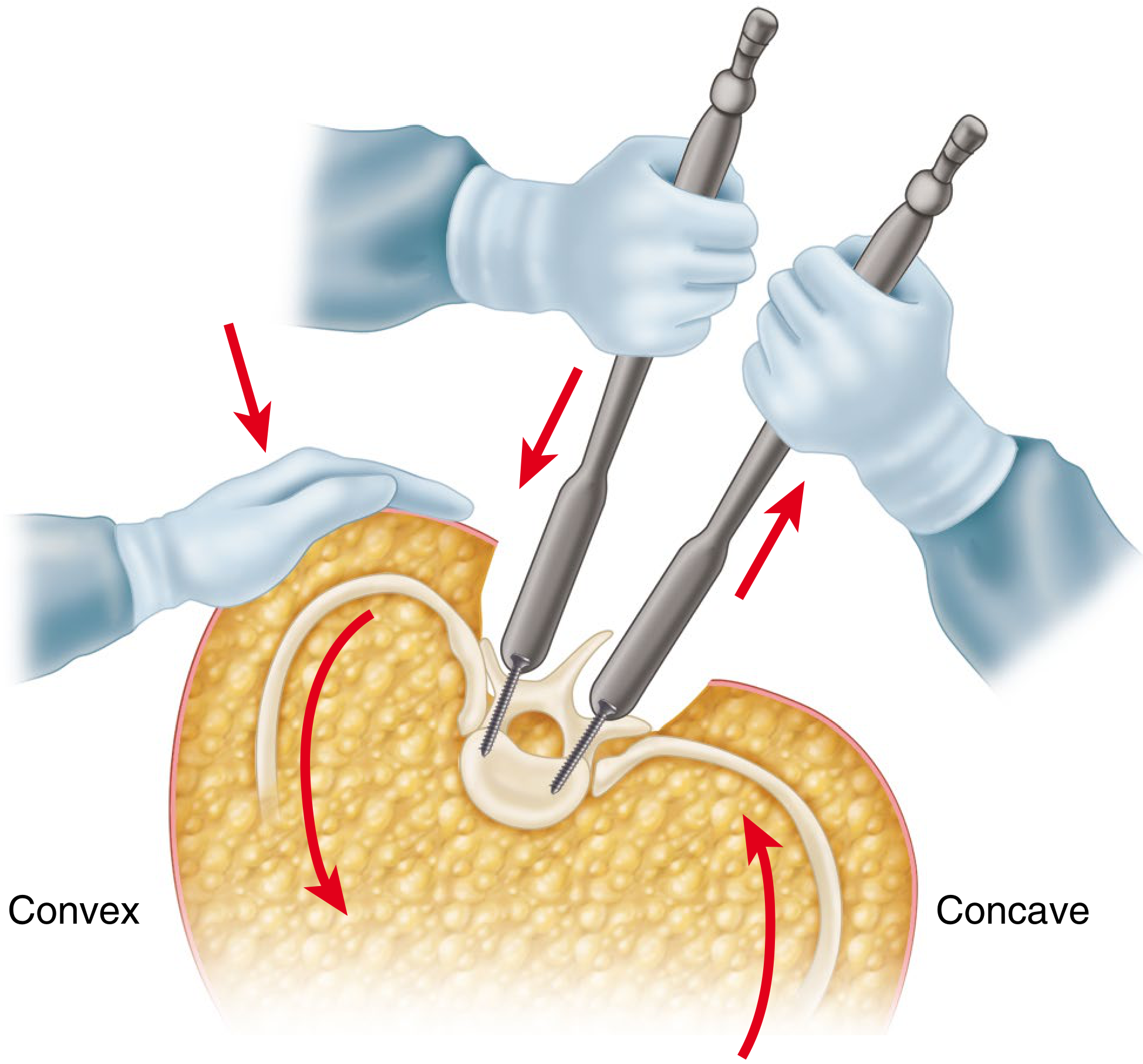
From Campbell's Operative Orthopaedics 15th Ed. 2026 - Direct Vertebral Rotation Technique (Figure 40.67)
DVR Step-by-Step Technique
1. Background - Why is Axial Rotation Important?
- Pushes the posterior ribs on the convex side posteriorly, creating the characteristic rib hump (costoparietal prominence)
- Contributes to thoracic hypokyphosis (sagittal flattening)
- Causes the cosmetically disfiguring trunk asymmetry that patients find most distressing
- Traditional correction addressed Cobb angle but left rotational deformity largely untreated
2. Indications
Primary Indication
- Adolescent Idiopathic Scoliosis (AIS) requiring surgical correction - the most common application
Specific Indications within AIS (and Lenke Classification)
- Lenke Type 1, 2, 3 curves - structural thoracic curves with significant apical vertebral rotation (Nash-Moe grade 2 or above, or >15° axial rotation on CT)
- Curves with Cobb angle >45-50° not responding to conservative treatment
- Progressive curves despite bracing in skeletally immature patients
- Curves with significant rib hump / costoparietal prominence (trunk asymmetry) where cosmetic improvement is a primary surgical goal
- Curves with thoracic hypokyphosis where sagittal restoration is needed simultaneously
- Rigid or stiff curves (flexibility <25% on side-bending radiographs) where simple rod derotation predictably fails to correct axial rotation - DVR is particularly beneficial here
- Adult idiopathic scoliosis - DVR provides ~16% better coronal correction in adults vs. ~14% in adolescents (PMC5486624)
Other Types of Scoliosis
- Neuromuscular scoliosis (cerebral palsy, muscular dystrophy) - when pedicle screw anchors are feasible
- Congenital scoliosis with rotational component
- Degenerative scoliosis in adults where pedicle screw-based posterior fusion is planned
Prerequisite Conditions
- Adequate bone quality to hold bilateral pedicle screws at all fusion levels
- Availability of monoaxial pedicle screws (preferred for DVR - see below)
- Surgeon experience with pedicle screw placement at all spinal levels
- Neuromonitoring capability (MEP/SSEP) available intraoperatively
- Mean arterial pressure (MAP) maintainable at ≥70 mmHg during corrective maneuvers
3. Contraindications
Absolute Contraindications
- Severe osteoporosis - insufficient bone stock to hold bilateral pedicle screws under the rotational forces of DVR (screw pullout risk)
- Inability to place bilateral pedicle screws at fusion levels (e.g., due to extremely narrow pedicles, severe pedicle dysplasia in congenital scoliosis)
- Active spinal infection (osteomyelitis, discitis) at planned fusion levels
- Existing neurological compromise at baseline where additional corrective forces risk complete deficit
Relative Contraindications
- Polyaxial screw systems only available - DVR is most effective with monoaxial screws; polyaxial screw heads do not transmit rotational torque as predictably (though specialized DVR-compatible polyaxial systems do exist)
- Very flexible curves (Cobb <40°, flexibility >80%) - simple rod derotation may suffice; the added complexity of DVR may not be justified
- Curves with concomitant severe sagittal deformity requiring simultaneous complex sagittal realignment (kyphosis correction takes priority)
- Poor intraoperative neuromonitoring signals - if MEP/SSEP signals are unreliable at baseline, proceeding with forceful DVR maneuvers poses elevated risk
- Inadequate intraoperative MAP support - DVR demands MAP ≥70 mmHg throughout; hemodynamically unstable patients should not have DVR performed
- Surgeon inexperience with DVR technique - the technique demands precise bilateral force coordination and understanding of spinal mechanics
4. Procedure and Methodology (Technique 40.14 - Campbell's Operative Orthopaedics 15th Ed. 2026)
Pre-operative Planning
- Full-length standing scoliosis radiographs (PA and lateral), supine side-bending films
- CT scan with axial cuts at apex to quantify Apical Vertebral Rotation (AVR) using Perdriolle method or Aaro-Dahlborn method
- Determine fusion levels using Lenke classification and stable/neutral vertebrae
- Select monoaxial pedicle screws (preferred) to maximize torque transmission during derotation
- Select appropriate rod diameter and material (5.5 mm cobalt-chrome preferred for stiff curves)
Patient Positioning and Anaesthesia
- Prone position on a Jackson table or 4-poster frame (important to allow abdomen to hang free, reducing epidural venous pressure)
- Total intravenous anaesthesia (TIVA) preferred as volatile agents suppress motor-evoked potentials (MEP)
- Baseline MEP and SSEP established before skin incision
- Arterial line for continuous MAP monitoring - MAP must be maintained ≥70 mmHg throughout correction maneuvers (Campbell's Operative Orthopaedics 15th Ed. 2026)
Surgical Steps
- Standard posterior midline approach from upper to lower instrumented vertebra (UIV to LIV)
- Subperiosteal dissection exposing transverse processes and facet joints to outer pedicle cortex
- Decortication of fusion bed
- Bilateral pedicle screws at every level to be fused - this is mandatory for DVR; unilateral or hook-based constructs cannot transmit the necessary torque
- Pedicle entry at junction of transverse process and superior facet, directed medially and caudally
- Free-hand technique, image guidance (fluoroscopy or navigation), or O-arm confirmation
- Monoaxial screws preferred at apical and juxta-apical levels for optimal force transmission
- Record MEP and SSEP before any corrective maneuver for comparison throughout
- Cut and contour the concave-side rod with appropriate sagittal profile
- Over-bend with extra kyphosis - this is critical; a kyphotic contour will pull the apical vertebrae posteriorly and correct apical lordosis/hypokyphosis
- Insert the contoured rod into the concave-side screw saddles using rod reducers as needed
- Begin securing from the neutral vertebra (least rotated level) distally
- Rotate the pre-contoured concave rod approximately 90° counterclockwise (for right thoracic curves)
- This achieves initial coronal and sagittal correction via translation and rod-vertebra interaction
- Do NOT fully tighten screws yet - rod must still slide to allow subsequent DVR maneuver
"Insert screw derotators onto the pedicle screws of the juxta-apical vertebrae on both the concave and convex sides and derotate the vertebrae as much as possible. This can be done in an en bloc fashion with multiple levels rotated simultaneously or at each individual level at a time." - Campbell's Operative Orthopaedics 15th Ed. 2026
- Right thoracic curves → vertebrae rotate clockwise in the transverse plane
- DVR applies counter-clockwise rotation (from the surgeon's overhead view)
| Approach | Description | Advantage |
|---|---|---|
| En bloc | All juxta-apical screws derotated simultaneously with linked derotators | Faster; more uniform force distribution |
| Sequential/Segmental | Each vertebra derotated individually from proximal to distal | More precise control; reduces peak force at any single screw |
- Identify the neutral vertebra distally (least rotated) and begin derotation proximal to this level
- Work toward the apex (most rotated level)
- Check neurophysiology after DVR maneuver
- If signal deteriorates >50% from baseline: STOP, reverse correction, allow MAP to improve, then reassess
- The "wake-up test" (Stagnara) may be used if neuromonitoring is unavailable or equivocal
- With DVR correction held, sequentially tighten set screws from neutral vertebra cranially and caudally
- Insert and secure the convex-side rod
- Apply compression and distraction as needed for final coronal balance
- Cross-links (transverse connectors) placed to complete the rigid frame
- Decorticate transverse processes, facets, and laminae
- Apply autologous iliac crest bone graft and/or allograft/DBM
- Layered closure over drains
Instruments Used
- Screw derotators - specialized handles that attach to the head of pedicle screws and allow controlled torque application (e.g., Stryker Xia3 SUK DVR system, Synthes, DePuy Viper)
- Rod derotation handle - for initial rod rotation
- Rod reducers - for seating rod into screw heads across the scoliotic curve
- French bender - for rod contouring
- Compression/distraction instruments
- Intraoperative neuromonitoring system (MEP + SSEP)
5. Comparison: DVR vs. Simple Rod Derotation (SRD)
| Parameter | Simple Rod Derotation (SRD) | Direct Vertebral Rotation (DVR) |
|---|---|---|
| Axial rotation correction | ~2.4-14.7% | 42-43% |
| Coronal Cobb correction | 68.9% | 79.6% (Lee & Suk 2004) |
| Rib hump reduction | Moderate | Significantly greater |
| Sagittal kyphosis | Risk of flattening | Does not reduce thoracic kyphosis |
| Complexity | Lower | Higher (requires bilateral screws + derotators) |
| Neurological risk | Lower | Slightly higher (greater corrective forces) |
| Blood loss | Less | Marginally more |
| Need for thoracoplasty | More often required | Less often required for rib hump |
| Screw requirements | Can use unilateral or hooks | Bilateral pedicle screws mandatory |
6. Advantages of DVR
1. Superior Axial (Transverse Plane) Derotation
2. Better Rib Hump Correction
3. Avoidance of Thoracoplasty
- Increased blood loss
- Persistent postoperative pain
- Pneumothorax
- Permanent reduction of pulmonary function DVR can eliminate or reduce the need for thoracoplasty in many cases.
4. Improved Coronal Correction
5. No Reduction of Thoracic Kyphosis
6. Reduced Fusion Extension
7. Better Outcomes in Rigid Curves
8. Segment-Level Control
7. Disadvantages of DVR
1. Higher Technical Complexity
- Bilateral pedicle screws at all levels (doubles screw count vs. unilateral)
- Specialized derotator instruments
- Precise coordination of bilateral forces simultaneously
- Greater surgical experience and specific training
2. Increased Neurological Risk
- Cause spinal cord distraction or tethering
- Transiently reduce spinal cord blood flow (hence the mandatory MAP ≥70 mmHg requirement)
- Produce pedicle fracture with displacement toward the spinal canal Continuous intraoperative neuromonitoring (MEP+SSEP) is absolutely mandatory and was not required as strictly for SRD.
3. Screw-Related Complications
- Screw pullout / plow - concentrated rotational forces at juxta-apical screws can exceed bone-implant interface strength, especially in osteopenic bone
- Pedicle fracture - particularly at thin thoracic pedicles
- Adjacent segment stress - forces can propagate to unfused adjacent levels
4. Requires Bilateral Pedicle Screws
- More screws = longer implantation time, greater blood loss during screw insertion
- More pedicle cortex violations = higher risk of misplacement (critical in thoracic spine where cord is large relative to canal)
- Higher implant cost
5. Longer Operative Time
6. Requires Monoaxial Screws
7. Limited Evidence of Clinical vs. Radiographic Benefit
8. Risk of Flat Back in Inexperienced Hands
8. Results from Key Evidence
| Study | Design | DVR Axial Correction | SRD Axial Correction | P value |
|---|---|---|---|---|
| Lee & Suk 2004 (PMID 14752361) | Prospective, n=38 | 42.5% (16.7°→9.6°) | 2.4% (16.1°→15.7°) | Significant |
| Abdel Rasol et al. 2024 (PMID 38504001) | RCT, n=36 | 42.2% (24.4°→14.4°) | 14.65% (25°→21.4°) | P<0.001 |
| PMC5486624 | Cohort, n=36 | ~14% better coronal correction | Reference | Significant |
| Panya-amornwat et al. (JMAT 2017) | Comparative | Bipedicular DVR better than SRD | Reference | Significant |
9. Modifications and Related Techniques
| Technique | Description | Relation to DVR |
|---|---|---|
| Vertebral Coplanar Alignment (VCA) | Rotates spine so pedicle screws of all levels align in same plane | Variant of DVR principle |
| Segmental DVR | DVR applied level by level from neutral to apex | More controlled, lower peak force |
| En bloc DVR | All juxta-apical levels derotated simultaneously | Faster, more uniform |
| Apical vertebral derotation (AVD) | DVR focused only at apex | Simplified version for mild curves |
| Simple Rod Derotation (SRD) | Conventional: only rod rotated, no direct screw derotators | Predecessor technique |
| Thoracoplasty | Rib resection to reduce rib hump | Mostly replaced by DVR |
| Ponte osteotomies | Posterior column release to improve flexibility before DVR | Adjunct to DVR in rigid curves |
10. Summary
| Feature | Detail |
|---|---|
| Who described it | Lee SM, Suk SI (2004) |
| Core principle | Direct axial torque to vertebral bodies via bilateral pedicle screw derotators |
| Direction | Opposite to the scoliotic vertebral rotation |
| Starting point | Neutral vertebra distally → work toward apex |
| Key requirement | MAP ≥70 mmHg + continuous MEP/SSEP monitoring |
| Best evidence | RCT (PMID 38504001): 42% vs. 15% axial correction |
| Main advantage | True 3D correction - especially transverse plane |
| Main risk | Neurological injury from excessive rotational forces |
| Bottom line | DVR is the technique of choice for AIS with significant rib hump and axial rotation, especially in stiff/rigid curves |
- Campbell's Operative Orthopaedics, 15th Ed. 2026 - Technique 40.14 (direct textbook reference)
- Lee SM et al., Spine 2004 (PMID 14752361) - original DVR description
- Abdel Rasol et al., Spine Deform 2024 (PMID 38504001) - RCT comparing DVR vs. SRD
- PMC5486624 - Impact of DVR on radiographic outcome - cohort study on mechanisms and outcomes
- MDPI J Clin Med 2025 - Narrative review of AIS deformity correction techniques
- Stryker Xia3 SUK DVR Surgical Technique Manual