
What is anteversion and retroversion of the neck of femur
The neck of femur is normally angled forward (anteriorly) relative to the shaft - this forward tilt is called anteversion. The normal angle is roughly 10-15° in adults. When this angle is reduced or reversed (neck tilted backward), it is called retroversion.
Searching sources...
Reading File
Now let me search the medical library for content on femoral neck anteversion and retroversion.
Finding Sources
Finding Sources
Good results found. Let me read the most relevant sections in parallel.
Reading File
Reading File
Reading File
Excellent - very rich content. Let me fetch the key diagram on anteversion angles.
Loading Image
Finding Sources
I have all the key content. Here is a thorough answer:
Anteversion and Retroversion of the Neck of Femur
The Reference Axes
To understand these terms, you need two reference lines drawn on the femur when viewed from above (superior/axial view):
- Femoral neck axis - a line drawn along the long axis of the femoral neck, from the center of the femoral head to the base of the neck.
- Transcondylar (condylar) axis - a line drawn through the two femoral condyles at the knee.
The angle between these two axes, measured in the transverse (horizontal) plane, is called the angle of torsion or angle of femoral neck version.
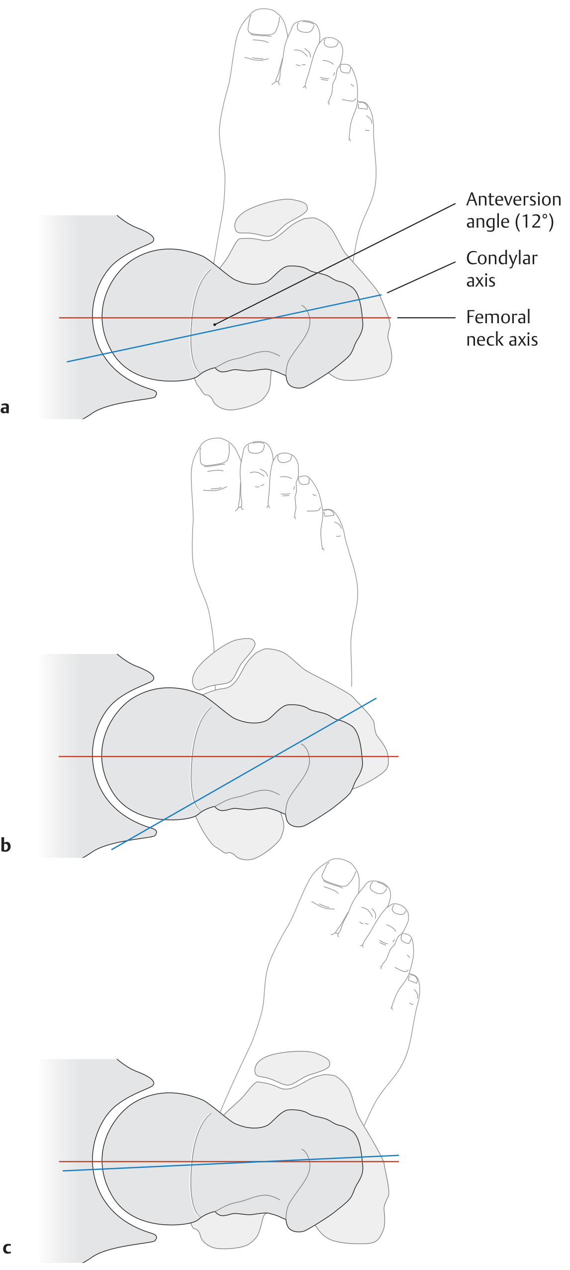
The diagram above shows: (a) normal anteversion ~12°, (b) increased anteversion - coxa anteverta, (c) retroversion - coxa retroverta. Red line = condylar axis; blue line = femoral neck axis.
Anteversion (Coxa Anteverta)
Definition: The femoral neck axis points anteriorly (forward) relative to the condylar axis. In other words, when the femoral condyles lie in the coronal plane (facing directly forward), the femoral head and neck are directed forward and medially.
Normal angle:
- Adults: approximately 10-15° (some sources quote 12°, others 15-25°)
- Neonates/infants: 30-40° at birth - all femurs are anteverted at birth
- Decreases progressively through childhood, reaching the adult value by the end of the 2nd decade of life
Clinical significance of increased anteversion:
- Called coxa anteverta when the angle is excessively large
- The hip has excessive internal rotation range and limited external rotation
- The patient walks with a "toeing-in" gait (in-toed or pigeon-toed gait)
- In children: persistent femoral neck anteversion is best assessed with the patient prone - excessive internal rotation of the hip is the hallmark finding
- All femurs are anteverted at birth, and spontaneous improvement usually occurs as the femur lengthens and rotates during growth
- If persistent beyond age 10-12 years with functional difficulty, corrective derotational osteotomy may be justified
- Compensatory external tibial torsion may develop, normalizing the foot progression angle but causing the "miserable malalignment syndrome" (knee pain, instability)
Retroversion (Coxa Retroverta)
Definition: The femoral neck axis points posteriorly (backward) relative to the condylar axis - the neck is directed backward instead of forward.
Clinical significance:
- Called coxa retroverta
- The patient walks with a "toeing-out" gait (out-toed gait)
- There is excessive external rotation at the hip and limitation of internal rotation
- Associated with conditions like femoroacetabular impingement (cam/pincer type) and slipped capital femoral epiphysis (SCFE) in some contexts
How to Measure
- Imaging: Axial CT of the femoral neck and distal femur can be superimposed to measure the angle between the femoral neck axis and the posterior condylar axis. Normal is 10-20° of anteversion on CT.
- Clinical test: The angle difference between a radiographic true lateral of the knee and hip also represents hip anteversion.
Summary Table
| Feature | Anteversion | Retroversion |
|---|---|---|
| Direction of neck | Forward (anterior) | Backward (posterior) |
| Normal adult angle | 10-15° (12-25° by some sources) | 0° or negative |
| At birth | 30-40° (physiological) | - |
| Latin term | Coxa anteverta | Coxa retroverta |
| Gait | Toeing-in (in-toed) | Toeing-out (out-toed) |
| Hip rotation | Excess internal rotation | Excess external rotation |
Sources:
- General Anatomy and Musculoskeletal System, THIEME Atlas - p. 437-438
- Rockwood and Green's Fractures in Adults, 10th ed. 2025 - p. 2642
- Bailey and Love's Short Practice of Surgery, 28th ed. - p. 631
Anteversion is normal or retroversion?
Anteversion is normal.
The femoral neck naturally points forward (anteriorly) relative to the transcondylar axis — this is the normal anatomical configuration in all humans.
| Detail | |
|---|---|
| Normal state | Anteversion (~10–15° in adults) |
| At birth | ~30–40° anteversion (higher, reduces with growth) |
| Retroversion | Abnormal — neck points backward, causes toeing-out gait |
Why anteversion exists: It positions the femoral head optimally within the acetabulum during the normal standing and walking posture, allowing efficient load transmission through the hip joint.
Retroversion is pathological — it is associated with conditions like femoroacetabular impingement (FAI) and is not a normal developmental variant. The neck should always point somewhat forward; when it points backward, that is a deformity.
So in short: a small degree of anteversion = normal. Zero or negative (retroverted) = abnormal.
How to proceed distal end radius fracture with dorsal tilt treated with percutaneous k wire fixation
Distal radius fractures with dorsal tilt (Colles-type) are reduced by traction and palmar flexion, then stabilized with K-wires passed percutaneously under fluoroscopic guidance. The classic technique uses two wires from the radial styloid and one from the ulnar side.
Searching sources...
Reading File
Finding Sources
Finding Sources
Finding Sources
Finding Sources
Found the exact technique section. Let me read it in full.
Reading File
Reading File
Now let me also get the figure showing the wire placement technique.
Finding Sources
Reading File
Let me get the figure that accompanies the technique (Figure 62.92).
Finding Sources
Now let me fetch Figure 62.92 from Campbell's to show the wire placement technique visually.
Reading File
I have all the content needed. Here is the complete step-by-step guide:
Distal Radius Fracture with Dorsal Tilt - Percutaneous K-Wire Fixation
Background
A distal radius fracture with dorsal tilt (Colles-type fracture) has the distal fragment displaced dorsally, radially, and in supination. The goal is to restore:
| Parameter | Normal | Acceptable after reduction |
|---|---|---|
| Palmar (volar) tilt | 11° volar | Less than 10° dorsal tilt |
| Radial height | 12 mm | Less than 3 mm shortening |
| Radial inclination | 20° | No less than 10° |
| Ulnar variance | ±2 mm | No more than 2 mm shortening |
| Intraarticular step/gap | None | Less than 2 mm |
Indications for Percutaneous K-Wire Fixation
- Metaphyseal instability after closed reduction
- Simpler intraarticular displacement (not severely comminuted)
- Fractures that cannot be maintained in cast alone
- Preferred when ORIF is not required
Step-by-Step Technique (Glickel et al. - Campbell's Operative Orthopaedics)
Step 1 - Anesthesia and Setup
- Brachial block or general anesthesia
- Supine position, arm on radiolucent hand table
- C-arm fluoroscope available
Step 2 - Reduction (Fig. A)
- Place thumb and index fingers in finger traps for longitudinal traction (typically 10 lb / ~4.5 kg)
- This allows disimpaction of the fracture
- Apply dorsal-to-palmar pressure with the thumb over the distal fragment to correct dorsal tilt
- Simultaneously apply ulnar deviation to correct radial displacement
- The wrist is brought into slight palmar flexion and ulnar deviation (cotton-loader position)
Step 3 - Fluoroscopic Assessment
- Evaluate reduction on AP and lateral fluoroscopic views
- If reduction is anatomic or acceptable (see table above) - proceed with pinning
- If reduction is not anatomic or there is severe comminution - consider ORIF
Step 4 - Radial Styloid Wires (Primary Wires)
- Make a 1.5 cm longitudinal incision starting at the radial styloid, proceeding distally (Fig. B)
- Identify and retract branches of the superficial radial nerve (blunt dissection)
- Identify the first extensor compartment (APL and EPB tendons)
- Place two 1.6 mm (0.062-inch) K-wires in succession from the radial styloid:
- Directed across the fracture site
- To engage the ulnar cortex of the radius proximal to the fracture
- Place wires divergent in both AP and lateral planes for better stability
- Wires may be placed dorsal or volar to the first extensor compartment depending on fracture pattern
- Aim for subchondral bone distally (better bone density)
Step 5 - Dorsal Wire (Third Wire)
- Place one 1.6 mm K-wire percutaneously, starting at the dorsal rim of the distal radius just distal to Lister's tubercle (Fig. C)
- This wire is placed 90° orthogonally to the radial styloid wires
- Confirm starting point with fluoroscopy
- Drive in a proximal and volar direction across the fracture to engage the volar cortex of the radius proximal to the fracture
- This wire acts as a dorsal buttress against re-displacement
Step 6 - Additional Wires as Needed (Fig. D)
- Dorsal comminution: A second dorsal pin into the dorsal rim, or used as an intrafocal pin (Kapandji technique variant)
- Radial comminution with radial translation: Additional buttress pin from the radial aspect into the proximal ulnar cortex
- Crossed-pin configuration: Pins placed from the distal ulnar radial cortex to engage the intact radial cortex - useful for added stability
Step 7 - Wire Finishing
- Check reduction and wire position fluoroscopically on AP and lateral views
- Bend and cut the wires, leaving them superficial to the skin (for easy removal)
- Apply a well-padded splint
Postoperative Care
| Timepoint | Action |
|---|---|
| 0-2 weeks | Well-padded splint (controls rotation, minimizes pin site irritation) |
| 2-6 weeks | Soft arm cast applied |
| 6 weeks | Cast and K-wires removed |
| 6 weeks onwards | Supervised hand therapy begins - edema and pain management, soft-tissue and joint mobilization |
| 8-10 weeks | Functional use and normal activities encouraged |
Key Anatomical Notes
- Superficial radial nerve - must be identified and protected during radial styloid wire insertion (most common nerve injury)
- Lister's tubercle - key landmark for the dorsal wire entry point
- First extensor compartment - reference for radial styloid wire placement
- Wires placed in subchondral bone (distally) grip better due to higher bone density
Complications
- Tendon tethering, injury, or rupture (EPL most vulnerable with dorsal wire)
- Pin migration
- Superficial radial nerve injury
- Pin site infection
- Loss of reduction
Source: Campbell's Operative Orthopaedics, 15th Ed. 2026 - Technique 62.15 (Glickel et al.), p. 3638-3639
Cris cross k wire
The criss-cross (crossed) K-wire technique uses two wires inserted from opposite sides of the bone that cross each other at the fracture site, providing rotational and angular stability. It is used in distal radius fractures, supracondylar humerus fractures, and other metaphyseal fractures.
Searching sources...
Finding Sources
Finding Sources
Finding Sources
Finding Sources
Finding Sources
Finding Sources
Found the supracondylar section. Let me read it in detail.
Reading File
Reading File
Reading File
Let me get the lateral pin placement steps and the crossed pin diagram.
Reading File
I have rich content. Now I'll provide a comprehensive answer on the criss-cross (crossed) K-wire technique.
Criss-Cross (Crossed) K-Wire Fixation
What is it?
The criss-cross or crossed K-wire technique involves placing two (or more) K-wires from opposite sides of the bone, so they cross each other at or near the fracture site. This creates a biomechanically stable construct that resists:
- Angular displacement (varus/valgus)
- Rotational forces
- Translational forces
It is most classically described for supracondylar humerus fractures in children, but is also used for distal radius fractures, metacarpal fractures, and other metaphyseal fractures.
Criss-Cross K-Wire in Supracondylar Humerus Fracture (Classic Use)
This is the most common setting where criss-cross wiring is taught and tested.
Two Configurations Available:
| Configuration | Entry Points | Stability | Risk |
|---|---|---|---|
| Criss-cross (crossed) - one lateral + one medial | Lateral epicondyle + Medial epicondyle | Highest biomechanical stability in vitro | 7.7% ulnar nerve injury (medial pin) |
| Lateral-only (parallel/divergent) - two or three lateral pins | Both from lateral side | Equal to crossed pins in vivo | No ulnar nerve risk |
Key point from Campbell's: Although crossed medial and lateral pins are more stable than two lateral pins in vitro, two or three lateral pins appear to be equal to crossed pins in vivo. Most centers now use lateral-only pinning for most fractures, reserving a medial pin for very unstable fractures.
Step-by-Step Crossed K-Wire Technique (Supracondylar Fracture)
Step 1 - Reduction
- Patient supine, elbow on inverted image intensifier
- Countertraction on humerus; apply traction to forearm with elbow in extension
- Correct varus/valgus and rotational malalignment
- Gently flex elbow to 120° while applying anterior pressure on the olecranon to correct posterior displacement of the distal fragment
- Confirm reduction on AP and lateral fluoroscopy
Step 2 - First (Lateral) Pin
- From the lateral epicondyle, drive a 1.6 mm K-wire percutaneously
- Aim the wire to cross the fracture site and engage the medial cortex of the proximal fragment
- Confirm bicortical purchase under fluoroscopy
Step 3 - Second (Medial) Pin - The "criss-cross" component
- Make a 1-cm incision over the medial epicondyle
- Spread soft tissues so the epicondyle is visible
- Use a retractor to protect the ulnar nerve (the nerve lies just posterior to the medial epicondyle)
- A small soft-tissue drill sleeve can also be used
- Drive the wire from the medial epicondyle, crossing the fracture site, to engage the lateral cortex of the proximal fragment
- The two wires now cross each other at the fracture site (criss-cross pattern)
Step 4 - Check Stability
- Extend the elbow as far as possible without bending the pins
- Stress test under fluoroscopy (rotate and stress the elbow) to check if a third pin is needed
- Compare carrying angle with the normal contralateral elbow
Step 5 - Finishing
- Cut and bend pins outside the skin
- Apply a well-padded posterior splint with elbow at 60° flexion (to allow for swelling)
Postoperative Care:
- At 1 week: convert to long arm cast at 90° elbow flexion
- At 3-4 weeks: cast and pins removed
- Begin gentle range-of-motion exercises
Criss-Cross K-Wire in Distal Radius Fracture
As described in the previous session, the crossed-pin configuration is used when there is:
- Radial comminution with pre-reduction radial translation
- Need for additional stability
Technique:
- Pins placed from the distal ulnar radial cortex, passed to engage the intact cortex radially
- These cross the pins already placed from the radial styloid side
- This buttresses against re-displacement in the radial direction
Why Criss-Cross is Biomechanically Superior
The crossed configuration provides stability in multiple planes because:
- Each wire blocks displacement in the opposite direction - the lateral wire blocks medial displacement, the medial wire blocks lateral displacement
- The two wires together resist rotation - a single wire cannot prevent rotation along its own axis, but two crossed wires interlock to prevent it
- The crossing point near the fracture site acts as a pivot lock
Key Risk: Ulnar Nerve Injury
The main risk of the medial pin in a criss-cross configuration at the elbow is iatrogenic ulnar nerve injury (reported rate: 7.7%).
To minimize this risk:
- Make a small skin incision (do not go blind percutaneously on the medial side)
- Spread soft tissues and directly visualize the medial epicondyle
- Use a retractor to protect the nerve
- Avoid pinning with the elbow in maximal flexion (nerve is most taut and at risk)
Source: Campbell's Operative Orthopaedics, 15th Ed. 2026 - Chapter 38 (Supracondylar fractures), Techniques 38.3 and 38.4
This is a shared conversation. Sign in to Orris to start your own chat.