
How to give I'm injection
intramuscular injection technique sites deltoid vastus lateralis
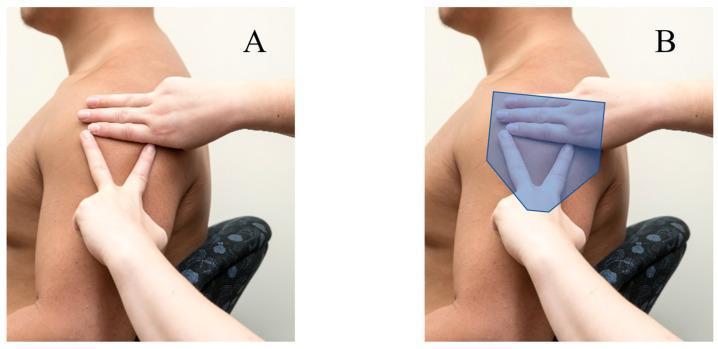
Clinical photograph and anatomical diagram demonstrating anatomical landmarking for intramuscular injection into the deltoid muscle. Figure A shows a manual palpation technique: one hand is placed horizontally across the superior aspect of the shoulder to identify the acromion process, while the other hand forms a 'V' shape with the index and middle fingers on the lateral aspect of the upper arm to locate the deltoid tuberosity. Figure B includes a semi-transparent blue overlay representing the anatomical boundaries and bulk of the deltoid muscle in relation to the hand positioning. This visual guide illustrates the Australian Immunisation Handbook's recommended technique for identifying the 'safe zone' for deltoid injections, minimizing the risk of shoulder injury related to vaccine administration (SIRVA) or subacromial-subdeltoid bursitis. The educational focus is on surface anatomy, musculoskeletal landmarks, and clinical nursing skills for safe immunization practices.
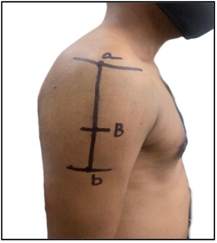
This clinical photograph illustrates the surface anatomy and landmarks for identifying safe intramuscular injection (IMI) sites in the deltoid muscle region. Black ink markings on the subject's right lateral shoulder and upper arm delineate anatomical references and distance measurements. A superior horizontal line marked 'a' indicates the lateral border of the acromion process. A vertical line descends from this point toward the inferior aspect of the deltoid. A midpoint intersection marked 'B' represents a distance of 7.4 cm from the acromion border, identified as a safe zone for injection to avoid the subacromial bursa and the axillary nerve. A final horizontal line and label 'b' at the base of the vertical markings indicate the deltoid tuberosity, the muscle's distal insertion point. The image serves as an educational guide for healthcare professionals to visualize the neurovascular 'danger zones' (proximal humerus surgical neck, axillary nerve, and posterior circumflex humeral artery) versus safer distal sites for vaccine or medication administration.
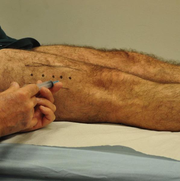
This clinical photograph demonstrates the procedural administration of Botulinum Toxin Type A (BoNT-A) into the vastus lateralis muscle of a patient's lower extremity. The patient is positioned supine, with the lateral aspect of the thigh exposed. Anatomical marking is evident on the skin, featuring five discrete, linearly arranged dark dots spaced at approximately 3 cm intervals, serving as specific injection site targets. These marks are positioned 3–5 cm proximal to the patella on an oblique angle lateral to the midline. A healthcare provider's hand is visible holding a standard medical syringe with a fine-gauge needle, positioned to perform an intramuscular injection at one of the marked sites. The educational focus is on the standardized clinical protocol for treating musculoskeletal conditions, such as patellofemoral pain syndrome or muscle imbalances, through targeted chemodenervation. The image highlights the importance of precise surface anatomy mapping for outpatient office-based procedures performed without continuous image guidance.
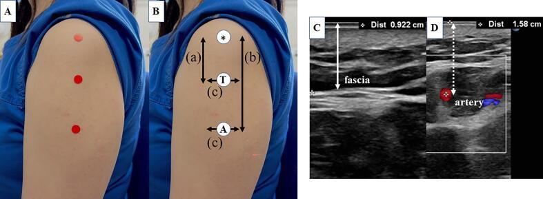
A multi-panel figure illustrating anatomical landmarks and ultrasound measurements for intramuscular vaccine injection sites in the deltoid muscle. Panels A and B are clinical photographs of a human arm showing three reference points: the mid-acromion lateral border (*), the three-finger breadth method injection point (T), and the axillary method injection point (A). Vertical and horizontal measurement lines (a, b, c) map the spatial relationships between the acromion and these injection sites. Panels C and D are corresponding B-mode and Doppler ultrasound images. Image C shows the subcutaneous layer and deltoid fascia, measuring a skin-to-fascia distance of 0.922 cm. Image D displays a Doppler ultrasound cross-section showing an adjacent artery (posterior circumflex humeral artery branch) with a measured skin-to-artery depth of 1.58 cm. The educational focus is on the safe depth of intramuscular injections to avoid vascular injury or Shoulder Injury Related to Vaccine Administration (SIRVA) by accurately locating anatomical landmarks and quantifying tissue thickness.
How to Give an Intramuscular (IM) Injection
1. Equipment You Need
- Correct medication (check 5 rights: right patient, drug, dose, route, time)
- Syringe (appropriate size for volume)
- Needle: 22-25 gauge, 1-1.5 inch for most adults (longer for obese patients to reach muscle)
- Alcohol swabs
- Gloves
- Sharps container
2. Choose the Injection Site
| Site | Best For | Key Landmark |
|---|---|---|
| Deltoid (upper arm) | Adults, vaccines, small volumes (<2 mL) | 2-3 finger-widths below the acromion process |
| Vastus lateralis (outer thigh) | Infants, children, self-injection | Middle third of the outer thigh |
| Ventrogluteal (hip) | Large volumes, oily depots | Greater trochanter + anterior superior iliac spine |
| Dorsogluteal (buttock) | Large volumes (>4 mL) | Upper outer quadrant - use with caution (sciatic nerve risk) |
Note: The buttocks are generally discouraged for routine IM injections because of the risk of sciatic nerve damage and because some vaccines (e.g., hepatitis B) show reduced immune response when injected into gluteal fat rather than muscle - Goldman-Cecil Medicine.
3. Step-by-Step Procedure
- Wash hands thoroughly and put on gloves.
- Prepare the medication - draw it up into the syringe, expel air bubbles, and cap the needle.
- Position the patient - relax the muscle (arm hanging loose for deltoid; lying down/sitting for thigh/gluteal sites).
- Clean the skin - wipe with an alcohol swab in a circular motion (5-8 cm diameter) and let it dry for at least 30 seconds.
- Spread or bunch the skin:
- Spread (Z-track method): Pull the skin 2-3 cm to one side before injecting - this seals medication in the muscle and reduces leakage, especially recommended for oily depot injections.
- Bunch: Pinch muscle in thin patients.
- Insert the needle at 90° to the skin in a smooth, dart-like motion.
- Aspirate (pull back the plunger): Policy varies - current WHO/CDC guidance no longer routinely recommends aspiration for most vaccine IM injections. However, aspiration is still recommended for oil-based depot antipsychotic injections (e.g., flupentixol decanoate) to confirm the needle is not intravascular, per Maudsley Prescribing Guidelines.
- Inject slowly - push the plunger steadily (approximately 1 mL per 10 seconds).
- Withdraw the needle smoothly at the same angle, then release skin if using Z-track.
- Apply gentle pressure with a cotton ball or gauze - do not rub (rubbing can cause tissue irritation).
- Dispose of the needle and syringe immediately in a sharps container - do not recap.
- Document the site, drug, dose, batch number, and any reactions.
4. Volume Limits Per Site
| Site | Maximum Volume |
|---|---|
| Deltoid | 1-2 mL |
| Vastus lateralis | 1-5 mL (adults), 1-3 mL (children) |
| Ventrogluteal | Up to 4 mL |
| Dorsogluteal | Up to 4-5 mL |
Volumes greater than 3 mL into the gluteal muscle are uncomfortable - Goldman-Cecil Medicine recommends against large gluteal volumes for this reason.
5. Key Tips and Precautions
- Rotate sites when giving repeated injections to prevent lipodystrophy and tissue damage.
- Z-track technique is recommended for all IM injections, especially oily or irritating medications.
- Never inject into bruised, infected, or edematous tissue.
- Warm the medication to room temperature if refrigerated - cold injections are painful.
- Needle length matters: Too short = subcutaneous deposit (poor absorption); too long = periosteal injection (very painful). For obese adults, a 1.5-inch needle may still not reach muscle - some require ultrasound guidance or a longer needle.
- For depot antipsychotics, always follow the specific product's licensed site (e.g., paliperidone palmitate 3-monthly is licensed for deltoid administration only).
Ventrogluteal site
ventrogluteal injection site landmark hand placement technique
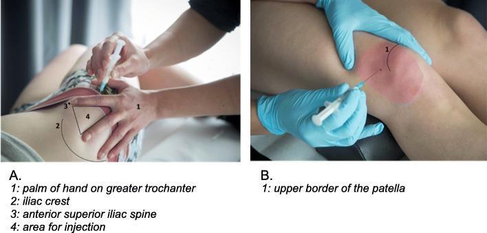
This composite educational image illustrates two clinical procedural techniques: ventrogluteal intramuscular (IM) injection and superolateral intra-articular (IA) knee injection. Panel A displays the anatomical landmarks for a ventrogluteal injection. It shows a hand positioned with the palm on the greater trochanter (1) and fingers spread toward the iliac crest (2) and the anterior superior iliac spine (3). The triangular area between the index and middle fingers (4) marks the safe injection site, chosen to avoid the sciatic nerve and penetrate less subcutaneous fat. Panel B demonstrates the superolateral approach for an intra-articular knee injection. The practitioner, wearing sterile blue gloves, locates the injection site approximately 1 cm lateral to the lateral border of the patella and just below its upper border (1). A syringe is shown inserted at this site, targeting the joint space. These clinical photographs serve as a procedural guide for medical students and practitioners, emphasizing the use of palpable bony landmarks to ensure accurate needle placement and patient safety during corticosteroid or analgesic administration.
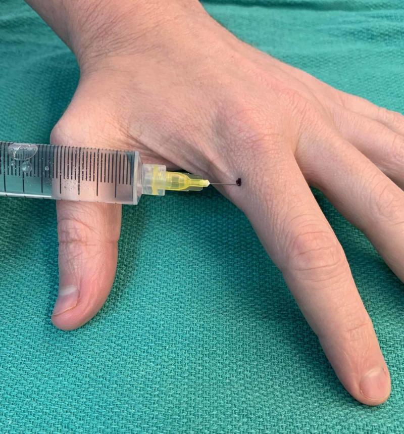
A procedural clinical photograph demonstrating a subcutaneous injection technique on the left hand. The dorsal view shows a hand resting on a green surgical drape. A clear plastic syringe, containing a translucent liquid and graduated volumetric markings, is oriented horizontally. It is fitted with a 30-gauge needle on a yellow hub, which is inserted into the radial side of the second digit (index finger). The injection site is located approximately 1 cm distal to the metacarpophalangeal joint, marked by a small dark ink dot at the junction of the palmar and dorsal skin. This specific placement is used for botulinum toxin administration in the treatment of Raynaud's phenomenon or digital ischemia, targeting the vicinity of the digital arteries while minimizing diffusion to the intrinsic thenar muscles. The syringe and hand positioning illustrate the proper angle and anatomical landmarks for targeted digital neurovascular bundle injections.
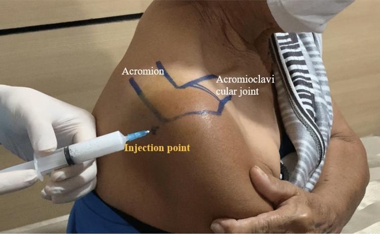
This clinical photograph demonstrates the procedural landmarks for a posterior approach subacromial corticosteroid injection in a human shoulder. The image displays the posterior and lateral aspect of a patient's shoulder with surface anatomy clearly delineated in blue ink. Key anatomical landmarks are labeled, including the 'Acromion' (specifically the posterolateral corner) and the 'Acromioclavicular joint' located superiorly. A specific 'Injection point' is marked with a small cross, situated approximately 2 cm inferior and 2 cm medial to the posterolateral acromial corner. A clinician's gloved hand is shown holding a syringe filled with a white, opaque suspension (consistent with a corticosteroid like triamcinolone acetonide). The needle tip is positioned precisely at the designated injection point, oriented at approximately a 45-degree angle to access the subacromial space. This visual serves as an educational guide for orthopedic or rheumatologic procedures, emphasizing aseptic technique and landmark-guided needle placement for treating subacromial impingement syndrome.
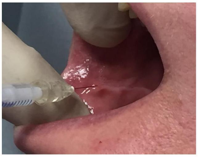
This clinical photograph demonstrates an intraoral endobuccal injection procedure targeting the buccinator muscle. A gloved hand is shown retracting the labial commissure to provide clear access to the jugal mucosa (inner cheek lining). A fine-gauge metallic needle, attached to a syringe containing clear fluid, is inserted perpendicular to a visible horizontal dental impression line on the mucosa. This landmark represents the plane of dental occlusion where the buccinator muscle is in close contact with the teeth. The injection site is located approximately 1 cm from the buccal commissure. The mucosa appears healthy, moist, and pink, with light reflection indicating a normal surface texture. This technique is typically utilized for the administration of botulinum toxin in the management of post-paralytic facial synkinesis or hypertonia. The procedure emphasizes anatomical precision for intramuscular delivery through the oral route to minimize external scarring and maximize therapeutic targeting of the middle third of the face.
Ventrogluteal IM Injection Site
Why It's the Preferred Site
- No major nerves or blood vessels are nearby (sciatic nerve and inferior gluteal nerve are well away from this zone)
- Thicker muscle mass with less overlying subcutaneous fat than the dorsogluteal site
- The injection zone is well defined by palpable bony landmarks
- Lower risk of inadvertent sciatic nerve injury compared to the dorsogluteal
Anatomy
- The greater trochanter (below)
- The anterior superior iliac spine / ASIS (in front)
- The iliac crest (above)
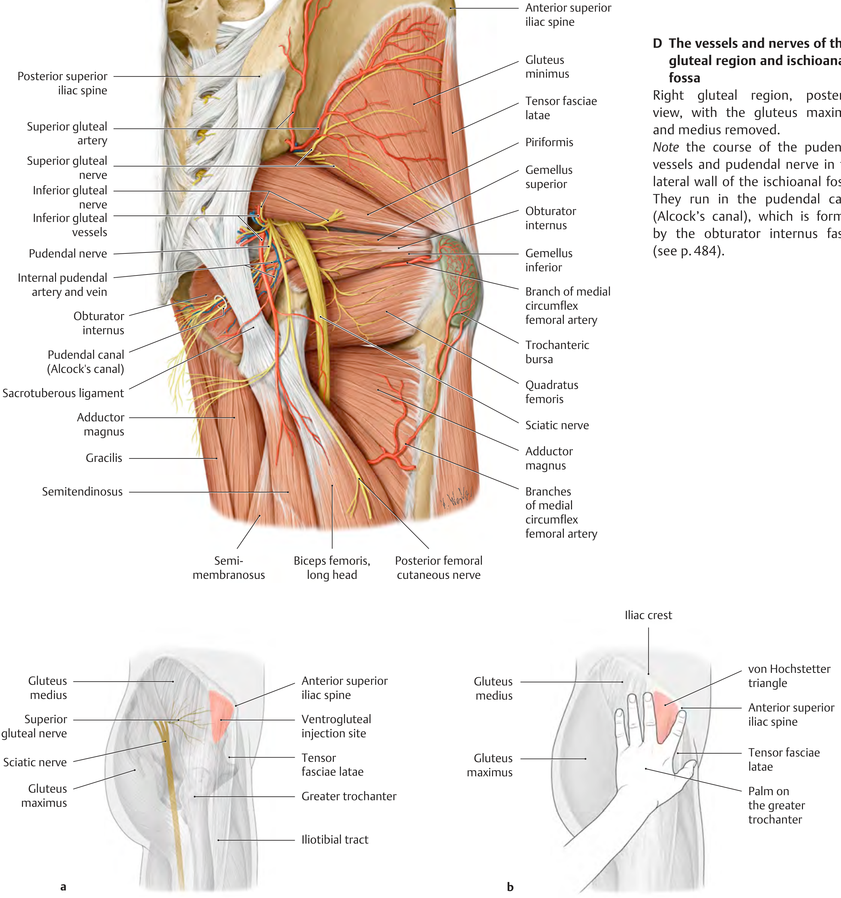
How to Locate the Site (Hand Placement Method)
| Step | What to Do |
|---|---|
| 1 | Place the palm flat on the greater trochanter |
| 2 | Point the index finger toward the ASIS (anterior superior iliac spine) |
| 3 | Abduct (spread) the middle finger away from the index finger, pointing it toward the iliac crest |
| 4 | The V-shaped triangle between your two fingers is the injection zone |
| 5 | Inject perpendicular (90°) to the skin into the center of this triangle |
For a right-sided injection: use your left hand. For a left-sided injection: use your right hand.
Practical Steps
- Position the patient - lying on their side (lateral decubitus) or prone. The hip should be relaxed - ask the patient to rotate the foot inward slightly to relax the gluteus medius.
- Identify landmarks using the hand method above.
- Clean the skin with an alcohol swab and allow to dry.
- Z-track technique - pull the skin 2-3 cm laterally before injecting (especially important for oily depot medications).
- Insert needle at 90° into the center of the von Hochstetter triangle.
- Aspirate if required by local policy or for oily depot injections.
- Inject slowly, then withdraw and release the Z-traction.
- Apply gentle pressure - do not massage.
Volume & Needle
| Parameter | Recommendation |
|---|---|
| Max volume | Up to 4 mL |
| Needle gauge | 21-23 G |
| Needle length | 1.5 inch (38 mm) for average adults; longer for obese patients |
| Angle | 90° |
Common Uses
- Depot antipsychotics (e.g., flupentixol decanoate, haloperidol decanoate)
- Opioid analgesics
- Antibiotics (e.g., penicillin G benzathine)
- Any large-volume IM medication in adults
How to use Z-track technique for oily depot medications
Z-track technique intramuscular injection skin displacement diagram
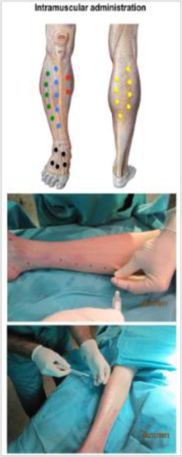
A composite clinical figure titled 'Intramuscular administration' illustrating the procedure for cell therapy in a patient's lower limb. The upper panel contains two anatomical diagrams of the lower leg showing targeted muscular injection points. The left diagram displays a multi-colored distribution of injection sites: green dots on the lateral calf, blue dots centrally, red dots medially, and black dots on the dorsal foot. The right diagram shows yellow dots distributed along the gastrocnemius muscle. The lower panels are clinical photographs depicting the real-world application of this protocol. The middle panel shows a patient's leg positioned horizontally on a blue sterile drape, with the skin pre-marked with dark dots for guidance. A medical professional in white gloves is seen prepping the site. The bottom panel shows the actual administration, where the professional is performing a minimally invasive intramuscular injection using a syringe. This visual serves as a guide for standardized adipose-derived mesenchymal stromal cell (Ad-MSC) delivery in clinical trials for conditions like critical limb ischemia (CLI).
Clinical photograph and anatomical diagram demonstrating anatomical landmarking for intramuscular injection into the deltoid muscle. Figure A shows a manual palpation technique: one hand is placed horizontally across the superior aspect of the shoulder to identify the acromion process, while the other hand forms a 'V' shape with the index and middle fingers on the lateral aspect of the upper arm to locate the deltoid tuberosity. Figure B includes a semi-transparent blue overlay representing the anatomical boundaries and bulk of the deltoid muscle in relation to the hand positioning. This visual guide illustrates the Australian Immunisation Handbook's recommended technique for identifying the 'safe zone' for deltoid injections, minimizing the risk of shoulder injury related to vaccine administration (SIRVA) or subacromial-subdeltoid bursitis. The educational focus is on surface anatomy, musculoskeletal landmarks, and clinical nursing skills for safe immunization practices.
Educational medical composite comparing conventional and modified surgical techniques for securing a Fusenig's chamber in a skin graft animal model. (A) Schematic cross-section of the conventional method: a two-part silicon chamber (upper and lower) is secured to the back skin using simple interrupted cutaneous sutures, leaving the Self-Assembled Skin Substitute (SASS) graft exposed within the chamber. (B) Schematic of the new method: the chamber is fixed using intramuscular sutures that anchor the device deeper into the back muscles. A tie-over bolster dressing is added atop the SASS graft to promote adherence. (C) 3D diagram of the 25mm upper chamber cap. (D, E) Comparative intraoperative clinical photographs. (D) shows the conventional setup with visible cutaneous sutures and a less stable chamber positioning. (E) illustrates the modified technique where intramuscular stitches provide a more secure, flush fixation of the chamber to the wound bed, minimizing displacement and graft contraction. These visual elements demonstrate surgical refinements in tissue engineering to improve graft take and stability.
Z-track technique IM injection oily depot medication step by step nursing procedure
Z-Track Technique for Oily Depot IM Injections
What It Does and Why It Matters
- Oil is thick and viscous - it tracks slowly along tissue planes if not sealed
- Oil in subcutaneous tissue causes pain, induration, sterile abscesses, and skin discolouration
- The full therapeutic dose must reach deep muscle to ensure correct slow-release pharmacokinetics
Per Maudsley Prescribing Guidelines: "As with all oil-based injections it is important to ensure, by aspiration before injection, that inadvertent intravascular entry does not occur."
Equipment
- Correct depot medication (drawn up at room temperature - never inject cold oily medication)
- Two needles: one to draw up (blunt/wide), one to inject (21 G, 1.5-2 inch for most adults)
- Syringe appropriate to volume (usually 2-3 mL)
- Alcohol swabs, gloves, sharps container
Always change the needle after drawing up the medication. The drawing-up needle may be contaminated with stopper particles and the oil coats the outside of the needle, which tracks into tissue during insertion if not replaced.
Step-by-Step Z-Track Technique
Before Injection
| Step | Action |
|---|---|
| 1 | Wash hands. Don gloves. |
| 2 | Draw up the medication through a wide-bore needle, then swap to the injection needle (21 G, 1.5-2 inch). |
| 3 | Hold the syringe upright and expel all air bubbles. |
| 4 | Warm the medication to body/room temperature if refrigerated - cold oil is highly viscous and painful. Roll the vial gently between your palms. |
| 5 | Position patient: lateral decubitus or prone for ventrogluteal/dorsogluteal sites. Relax the muscle. |
| 6 | Identify and clean the site with an alcohol swab. Allow to air dry fully (30 seconds). |
The Z-Track Displacement
| Step | Action | Why |
|---|---|---|
| 7 | Using your non-dominant hand, place the ulnar edge of your palm or two fingers firmly on the skin adjacent to the injection site. | Prepares for lateral pull |
| 8 | Pull the skin 2-3 cm (about 1 inch) laterally - away from the injection site - and hold it firmly throughout the injection. | Creates the displaced "Z" path |
| 9 | While maintaining this traction, insert the needle straight down at 90° in one smooth, dart-like motion. | Perpendicular entry reaches deep muscle |
Injection
| Step | Action |
|---|---|
| 10 | Aspirate: pull back the plunger for 5-10 seconds. If blood appears, withdraw immediately, discard the syringe, and prepare a fresh dose at a new site. No blood = proceed. |
| 11 | Inject slowly - push the plunger at approximately 1 mL per 10 seconds. For oily depots, inject even more slowly as viscous oil resists rapid delivery. |
| 12 | After fully injecting, wait 10 seconds before withdrawing - this allows the oil to begin dispersing and reduces backflow pressure. |
Withdrawal and Sealing
| Step | Action |
|---|---|
| 13 | Withdraw the needle at the same 90° angle in one smooth motion. |
| 14 | Immediately release the displaced skin - the tissue springs back, sealing the Z-shaped track. |
| 15 | Apply gentle pressure with a dry cotton ball or gauze. Do NOT massage - massaging forces oil back along the track into superficial tissues, defeating the technique. |
| 16 | Dispose of needle and syringe in sharps container immediately. Do not recap. |
| 17 | Document: drug name, batch number, dose, site used (e.g., "right ventrogluteal"), date, and any reactions. |
How the Seal Works - Visualised
BEFORE (skin pulled laterally):          AFTER (skin released):

  Skin ────────→  [displaced]              Skin ─────── [back to normal]
  SubQ ────────→  [displaced]              SubQ ─────── [sealed over track]
  Muscle ──────→  [needle in]              Muscle ───── [drug depot]

  Path: Skin → SubQ → Muscle              Zigzag seal: no straight channel
Key Points Specific to Oily Depots
| Issue | What to Do |
|---|---|
| Viscous oil won't draw up easily | Warm vial in hands, use a wide-bore (19-21 G) drawing needle |
| Aspiration is mandatory | Oil depots must be aspirated - intravascular injection of oily depot is a medical emergency (oil embolism) |
| Needle length | Use 1.5-2 inch (38-50 mm) needle for adults of average build; 2-2.5 inch for obese patients to ensure true IM depth |
| Volume per site | Maximum 3 mL ventrogluteal; if dose is larger, split across two sites |
| Site rotation | Alternate sides every dose and document which side was used - oil depots cause cumulative fibrosis if the same spot is used repeatedly |
| Do not rub | Rubbing accelerates absorption unevenly and can cause local skin reactions with oily vehicles |
| Post-injection syndrome (depot antipsychotics) | Keep patient observed for ~3 minutes post-injection for any immediate reactions (rare but includes post-injection delirium/sedation syndrome with olanzapine pamoate) |
Landmarks for ventrogluteal I'm
ventrogluteal IM injection landmarks von Hochstetter triangle greater trochanter ASIS iliac crest anatomy
This composite educational image illustrates two clinical procedural techniques: ventrogluteal intramuscular (IM) injection and superolateral intra-articular (IA) knee injection. Panel A displays the anatomical landmarks for a ventrogluteal injection. It shows a hand positioned with the palm on the greater trochanter (1) and fingers spread toward the iliac crest (2) and the anterior superior iliac spine (3). The triangular area between the index and middle fingers (4) marks the safe injection site, chosen to avoid the sciatic nerve and penetrate less subcutaneous fat. Panel B demonstrates the superolateral approach for an intra-articular knee injection. The practitioner, wearing sterile blue gloves, locates the injection site approximately 1 cm lateral to the lateral border of the patella and just below its upper border (1). A syringe is shown inserted at this site, targeting the joint space. These clinical photographs serve as a procedural guide for medical students and practitioners, emphasizing the use of palpable bony landmarks to ensure accurate needle placement and patient safety during corticosteroid or analgesic administration.
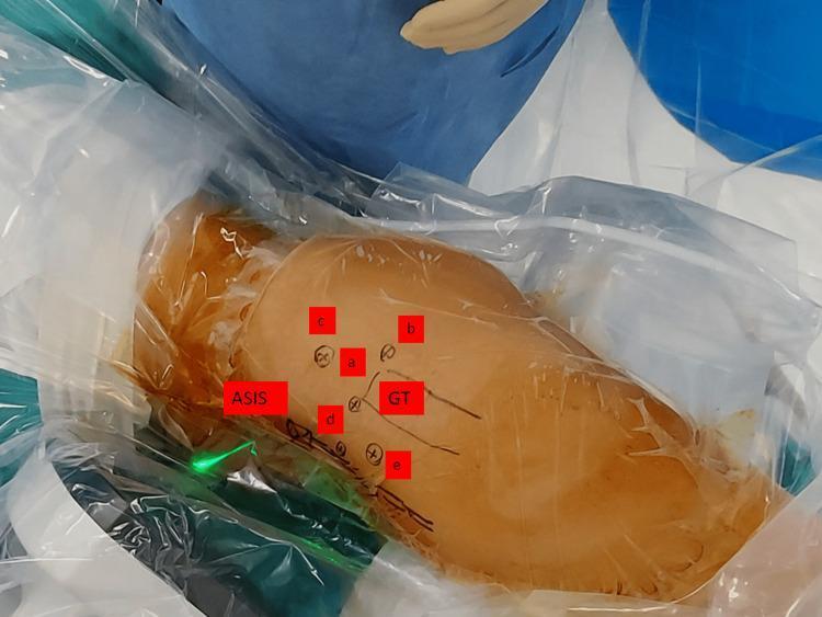
This clinical photograph illustrates the standard arthroscopic portals and anatomical landmarks of the hip, prepared for a surgical procedure. The patient is shown in a lateral decubitus position, covered with transparent sterile surgical drapes. Key surface landmarks are marked with red labels, including the Anterior Superior Iliac Spine (ASIS) and the Greater Trochanter (GT). Five specific arthroscopic portal sites are identified with lettered red labels: (a) anterolateral portal, located at the superior border of the greater trochanter; (b) posterolateral portal, situated posterior to the anterolateral portal; (c) supratrochanteric portal, positioned superiorly toward the iliac crest; (d) anterior portal, located distal to the ASIS; and (e) mid-anterior portal, positioned inferior and lateral to the anterior portal. This image serves as a procedural guide for orthopedic surgeons and residents, demonstrating the spatial relationships and surface anatomy required for safe portal placement during hip arthroscopy to access the central and peripheral compartments.
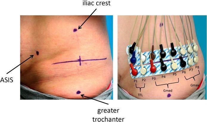
Clinical photograph in two panels demonstrating the standardized application of surface electromyography (SEMG) electrodes on the right gluteal region. The left panel shows surface anatomical landmarks marked with black dots: the anterior superior iliac spine (ASIS), iliac crest, and greater trochanter. A vertical reference line connects the iliac crest and greater trochanter, intersected by a horizontal marker line at the midpoint. The right panel illustrates the placement of sixteen monopolar Ag-AgCl solid gel electrode strips, labeled P1 through P8 from ventral to dorsal. These are organized into functional muscular groups: P1-P2 correspond to the tensor fasciae latae (TFL), P3-P5 to the gluteus medius (Gmed), and P6-P8 to the gluteus maximus (Gmax). A separate reference electrode is positioned superior to the ASIS. Color-coded lead wires (blue, brown, red, black, and white) connect the electrodes to a measurement device. This setup is utilized for assessing hip stabilizer activity during gait analysis and functional movement.
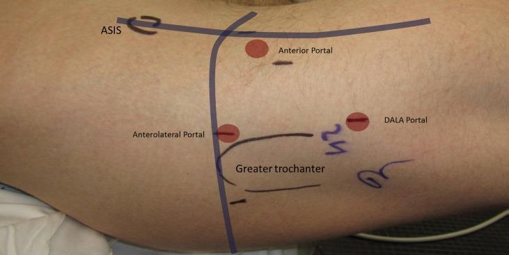
This clinical photograph illustrates the standard surface anatomy and portal placement for hip arthroscopy on a patient's right hip in a supine position. Key anatomical landmarks are marked on the skin, including the Anterior Superior Iliac Spine (ASIS) and the outline of the Greater Trochanter. Three primary arthroscopic portals are identified with red circular markers and labels: 1) The Anterolateral (AL) portal, situated approximately 1 cm anterior to the superior tip of the greater trochanter; 2) The Anterior portal, located at the intersection of a horizontal line from the AL portal and a vertical line distal to the ASIS; and 3) The Distal Anterolateral Accessory (DALA) portal, positioned distal and posterior to the AL portal. Reference lines are drawn to demonstrate the geometric relationship between these landmarks, ensuring safe surgical access to the central and peripheral compartments of the hip joint while avoiding neurovascular structures such as the lateral femoral cutaneous nerve and the superior gluteal nerve.
Ventrogluteal IM Injection - Landmarks
The 3 Bony Landmarks
| Landmark | Where to Feel It | Role |
|---|---|---|
| Greater Trochanter | Bony prominence on the lateral upper femur | Palm rests here - the anchor point |
| Anterior Superior Iliac Spine (ASIS) | Sharp bony point at the front of the iliac crest | Tip of index finger points here |
| Iliac Crest | The ridge of the pelvis running posteriorly from the ASIS | Forms the upper boundary of the triangle |
Hand Placement (The Von Hochstetter Method)
RIGHT side injection → use LEFT hand
LEFT side injection  → use RIGHT hand
Step by Step
Visual Reference
Why This Triangle Is Safe
| Structure | Where It Runs | Distance from Site |
|---|---|---|
| Sciatic nerve | Runs more posteriorly under gluteus maximus | Well away from the anterolateral triangle |
| Superior gluteal nerve | Runs above and medial to the injection zone | Protected by staying within the triangle |
| Superior gluteal artery | Exits above piriformis, runs medially | Not at risk within the V zone |
Common Mistakes to Avoid
| Mistake | Consequence |
|---|---|
| Injecting too posteriorly (into gluteus maximus) | Converts it to a dorsogluteal injection - sciatic nerve risk |
| Injecting too inferiorly (below the greater trochanter) | Into the tensor fasciae latae or vastus lateralis - not wrong but not ventrogluteal |
| Injecting too superiorly (above the iliac crest line) | Risk of injecting into the iliac bone or superficial tissue |
| Using the same hand as the side injecting | Landmarks become reversed and inaccurate |
| Not fully relaxing the muscle first | Harder to palpate landmarks, more painful injection |