
Bone screw s
Reading File
Bone screws are orthopedic implants used to fix fractures, anchor implants, or stabilize bones. Let me search the medical library for detailed content.
Searching sources...
Finding Sources
Searching the Web
bone screws types orthopedic classification cortical cancellous
Finding Sources
Finding Sources
Reading File
Reading File
Reading File
Reading File
Loading Image
Loading Image
Finding Sources
Reading File
Loading Image
Here is a comprehensive overview of bone screws from the authoritative orthopedic literature:
Bone Screws
Basic Mechanics
A bone screw is a mechanical device that converts torque into compression. The thread functions as an inclined plane that slowly pulls the objects it is embedded into together. The key forces acting on a screw are:
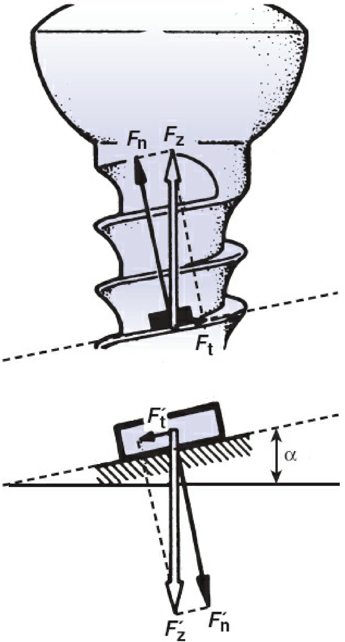
- Fn - normal (compressive) force against the screw head
- Ft - tangential (frictional) force along the thread
- Fr - resultant of the two forces
- Alpha (α) - angle of the screw thread; finer thread = smaller α = lower frictional force
Types of Bone Screws
1. Cortical Screws
- Designed for dense cortical bone
- Small pitch with shallow thread depth - optimizes insertion and holding power in hard bone
- Threaded their entire length
- Can function as positional screws (holds fragments without compression) or as lag screws (if the near cortex hole is over-drilled)
- Available in multiple diameters (e.g., standard 4.5 mm)
2. Cancellous Screws
- Designed for softer metaphyseal/cancellous bone
- Large pitch with deeper thread depth - maximizes purchase in porous bone
- More frequently used in metaphyseal regions (e.g., femoral neck, distal femur, tibial plateau, medial malleolus)
- The malleolar screw (4.5 mm) is a special variant with a self-tapping trephine tip
- Washers (plastic or metal) are often used with cancellous screws to increase surface area for compression and for reattaching ligamentous avulsions
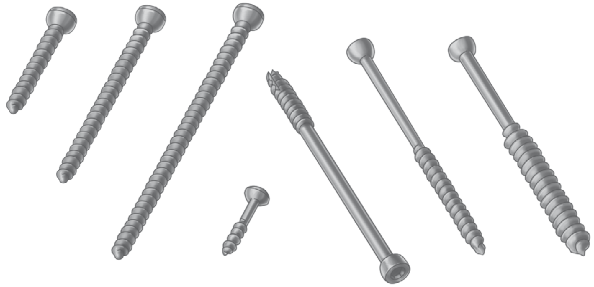
3. Lag Screws
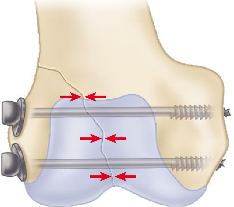
Lag screws generate interfragmentary compression and are used for articular and simple fracture patterns when absolute stability is required. They have purchase in the far fragment only - not the near fragment.
Two methods to achieve lag effect:
- Lag by technique: Drill an oversized glide hole in the near fragment (matching or larger than screw's major diameter), then drill a smaller hole in the far fragment approximating the minor diameter. As the screw tightens, the far fragment is drawn toward the near fragment.
- Lag by design (partially threaded screws): The unthreaded shaft glides through the near fragment automatically. The threaded portion must not cross the fracture line, or compression is lost.
4. Cannulated Screws
- Hollow core allowing placement over a guidewire
- Useful for percutaneous applications: femoral neck fixation, sacrum/SI joint screw fixation
- Tradeoff: increased core diameter reduces thread depth and may compromise pullout strength; higher cost; potentially increased infection risk due to greater implant surface area
5. Self-Tapping / Self-Drilling Screws
- Have a small cutting flute at the tip to remove bone debris - no separate tapping step needed
- Available in the same sizes as cortical screws
- Slightly less pullout strength than pre-tapped screws due to their design
- Frequently used in external fixation pins
6. Locking Screws
- Have threads on the screw head that mate with matching threads in the plate hole
- Create a fixed-angle construct between screw and plate - do not rely on plate-to-bone friction
- Generally have larger core diameters and shallower thread depths (emphasizing bending strength over stripping torque)
- Advantages:
- Particularly useful in poor bone quality (osteoporosis) or short fixation segments
- Common locations: proximal humerus, distal radius, distal femur
- Prevent disruption of fracture reduction (locked screws don't draw bone to plate)
- Disadvantages: higher profile (soft tissue irritation), significantly more expensive, may create too stiff a construct for callus formation
Screw Fixation Technique (AO/ASIF Principles)
The ASIF (Swiss) screw system is the standard for orthopedic osteosynthesis. Key points:
- Threads are more horizontal than machine screws
- Originally non-self-tapping (drill hole must be pre-tapped)
- Modern screws are self-tapping, in many sizes/lengths, using hexagonal or torx-type screwdrivers
- Cortical, cancellous, and malleolar designs are all available
For lag screw insertion (4.5 mm, AO technique):
- Reduce fracture; secure with forceps or provisional K-wires
- Plan screw to enter the middle of the fragment, equidistant from fracture edges, directed perpendicular to the fracture line (maximizes compression)
- Drill the glide hole in the near cortex
- Use a "top-hat" drill guide to drill the thread hole in the far fragment, co-linear with the glide hole
- Countersink the near cortex to increase contact area and reduce cracking risk
- Insert the screw
Summary Table
| Type | Thread Design | Bone Type | Primary Function |
|---|---|---|---|
| Cortical | Small pitch, shallow | Dense cortical | Positional or lag (by technique) |
| Cancellous | Large pitch, deep | Metaphyseal/cancellous | Lag (by design) or positional |
| Lag | Cancellous threads (typically) | Metaphyseal | Interfragmentary compression |
| Cannulated | Same as above but hollow | Variable | Guidewire-assisted placement |
| Self-tapping | Fluted tip | Cortical | Simplified insertion |
| Locking | Threaded head | Variable (poor bone quality) | Fixed-angle plate-screw construct |
Sources:
- Rockwood and Green's Fractures in Adults, 10th Ed (2025) - Campbell's Operative Orthopaedics, 15th Ed (2026)*, Chapters 12 and 58
Include and explain screw parts
Searching sources...
Finding Sources
Finding Sources
Searching the Web
bone screw parts anatomy head shaft thread tip pitch major minor diameter orthopedic
Reading File
Reading File
Loading Image
Loading Image
Finding Sources
Here is a detailed breakdown of all parts of a bone screw, sourced directly from Campbell's Operative Orthopaedics (15th Ed) and Rockwood & Green's Fractures in Adults (10th Ed):
Parts of a Bone Screw
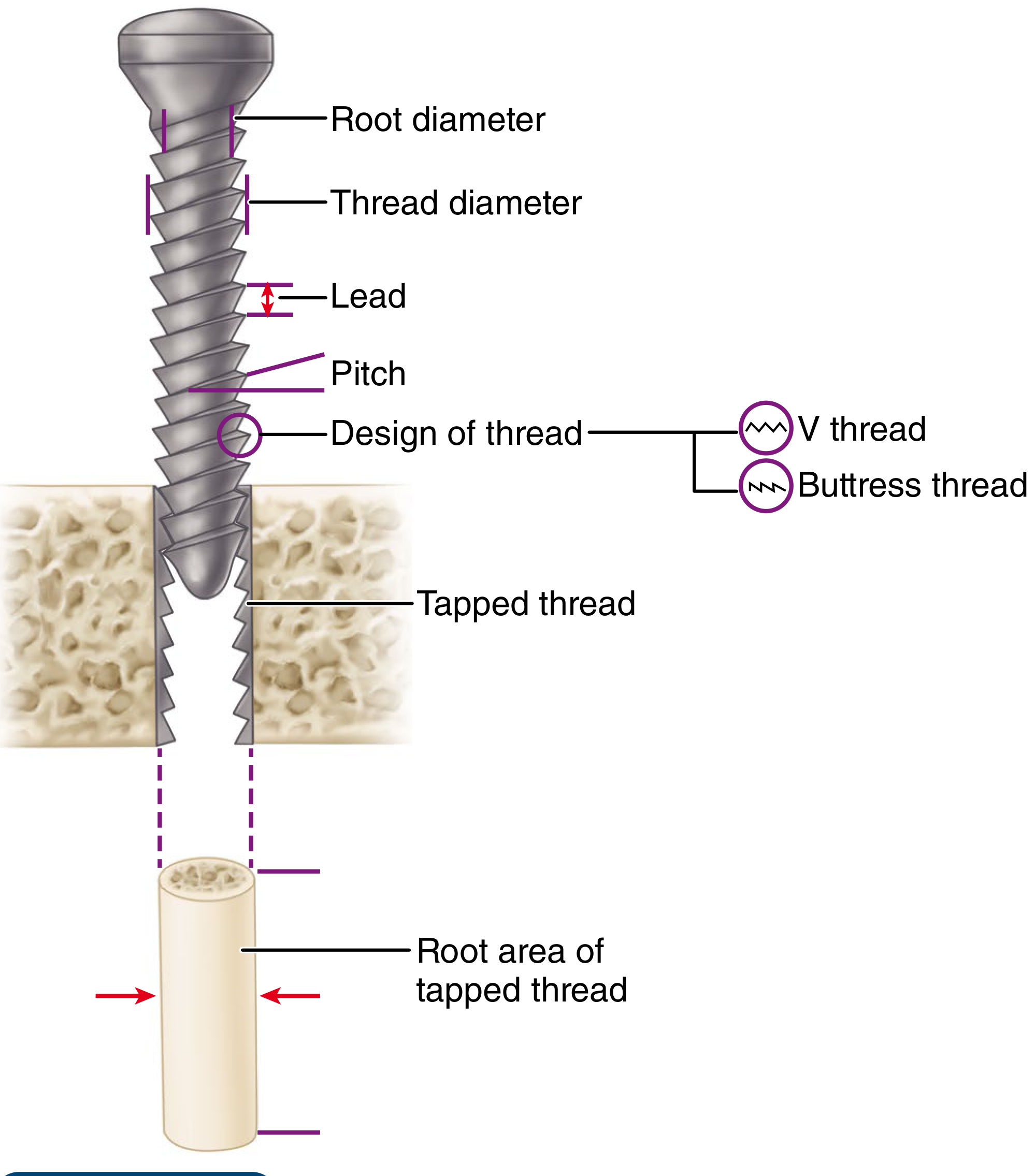
A bone screw has four main structural components: Head, Shaft, Thread, and Tip. Each plays a distinct mechanical role.
Structural Diagram
1. Head
The head is the proximal end of the screw. It has two functions:
-
Engages the screwdriver - the drive recess determines how torque is applied. Common designs:
- Hexagonal (most ASIF/AO screws)
- Torx (star-shaped, used by many modern manufacturers)
- Phillips / cruciate
- Slotted
-
Acts as a counterforce (buttress) - as the screw advances, the head contacts the near cortex or plate and prevents the screw from passing through entirely. This is how compression is generated: the head pushes a plate forward or drives one bone fragment toward another.
In locking screws, the head has peripheral threads that engage matching threads in the plate hole, creating a fixed-angle construct rather than relying on friction.
Countersinking - a shallow conical recess can be cut into the near cortex to receive the screw head flush with the bone surface, increasing contact area, reducing crack risk, and lowering implant prominence.
2. Shaft (Shank)
The shaft is the smooth, unthreaded cylindrical portion between the head and the threaded section.
- In a fully threaded screw, the shaft is minimal or absent - threads run to the head.
- In a partially threaded screw (e.g., cancellous lag screws), the shaft is intentionally left smooth so it can glide freely through the near fragment without purchasing it - this is the basis of the lag by design mechanism.
The shaft diameter has two measurements:
- Minor diameter (core/root diameter) - the inner diameter of the screw, measured at the base of the threads. This determines bending strength. A wider root diameter = greater resistance to fatigue fracture.
- Major diameter (thread/outer diameter) - the outer diameter measured at the thread crests. This is what is called the "screw size" clinically (e.g., 4.5 mm cortical screw).
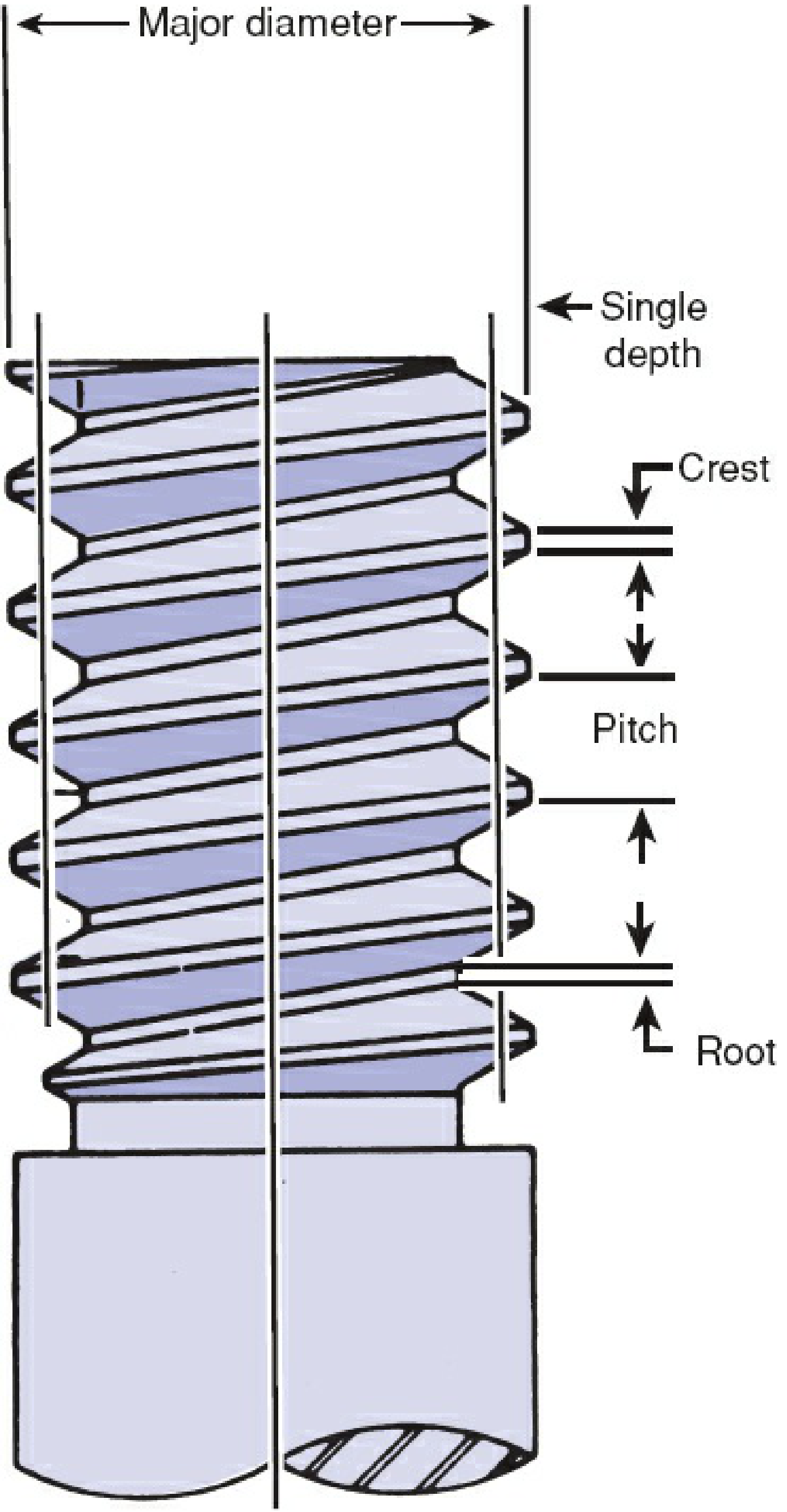
3. Thread
The thread is the helical ridge that spirals around the shaft. It is defined by several measurable parameters:
Thread Parameters
| Parameter | Definition | Clinical Relevance |
|---|---|---|
| Major (outer) diameter | Diameter measured at thread crests | Larger = more surface for bone contact |
| Minor (root/core) diameter | Diameter at thread base (valleys) | Determines bending & fatigue strength |
| Thread depth | Difference between major and minor diameter | Deeper threads = greater stripping torque & pullout resistance |
| Pitch | Distance between adjacent thread crests | Smaller pitch = more threads per mm, finer grip; larger pitch = faster advancement |
| Lead | Distance the screw advances per one full 360° turn | = Pitch in single-lead screws; determines insertion speed |
| Crest | Outermost point (peak) of the thread | Cuts into bone for purchase |
| Root | Innermost point (valley) of the thread | Core material - determines strength |
Thread Cross-Sectional Design
Two main profiles are used:
- Buttress thread (used in ASIF/AO screws) - asymmetric, with one near-vertical face and one sloped face. Resists pullout forces very effectively.
- V-thread (used in machine screws) - symmetric V-shape. Used less commonly in orthopaedic implants.
Thread Coverage (Partial vs. Full)
- Fully threaded screws - threads run the full length; used as positional screws or lag screws by technique (over-drilling the near cortex).
- Partially threaded screws - smooth shaft proximally, threads only distally; inherently function as lag screws by design.
Cortical vs. Cancellous Thread Design
| Feature | Cortical | Cancellous |
|---|---|---|
| Pitch | Small (fine) | Large (coarse) |
| Thread depth | Shallow | Deep |
| Bone type | Dense diaphyseal cortical bone | Soft metaphyseal cancellous bone |
| Rationale | Dense bone provides purchase with fine threads | Porous bone needs deep, wide threads to grip trabeculae |
4. Tip
The tip is the distal end of the screw that enters bone first. Two main designs:
-
Blunt/round tip - requires the drill hole to be pre-tapped before insertion. A separate tap instrument (matching the screw's diameter and thread profile) is used to pre-cut the thread path in bone, reducing friction and insertion torque.
-
Self-tapping tip - has sharp cutting flutes (typically 2-4 flutes) or a trocar point that cut the thread path as the screw is inserted, eliminating the need for a separate tapping step. Screws with four cutting flutes are easiest to insert and have the greatest holding power.
- Tradeoff: slightly less pullout strength than pre-tapped screws in dense bone, because the cutting flutes remove some bone material.
In cancellous bone, pre-tapping may actually decrease pullout strength (it removes the very trabeculae the threads need to grip), so self-tapping tips are preferred. Exception: very dense cancellous bone (e.g., young patients with femoral neck fractures) may need tapping to prevent excessive friction rotating the bone fragment during insertion.
Summary: All Parts at a Glance
HEAD
 ├── Drive recess (hex, torx, Phillips, slotted)
 └── Bearing surface / buttress (or threaded in locking screws)

SHAFT (SHANK)
 ├── Major diameter = outer/thread diameter (= nominal screw size)
 ├── Minor diameter = core/root diameter (→ bending strength)
 └── Smooth portion = unthreaded in partially threaded screws

THREAD
 ├── Crest (outermost peak)
 ├── Root (innermost valley)
 ├── Pitch (crest-to-crest distance)
 ├── Lead (advance per full turn)
 ├── Thread depth = (major − minor diameter) / 2  (→ pullout & stripping torque)
 └── Thread profile: buttress (AO) or V-thread

TIP
 ├── Round/blunt → requires pre-tapping
 └── Self-tapping → fluted cutting tip (2–4 flutes)
Sources: Campbell's Operative Orthopaedics 15th Ed (2026), p. 3287 | Rockwood and Green's Fractures in Adults 10th Ed (2025), pp. 470-471
This is a shared conversation. Sign in to Orris to start your own chat.