Knee biomechanics in complete details normal biomechanics movements locking and unlocking application of biomechanics in arthroplasty and arthroscopy with appropriate images and illustration
Reading File
Finding Sources
Finding Sources
Searching Images
knee biomechanics movements locking unlocking screw home mechanism
Reading File
Finding Sources
Finding Sources
Searching Images
knee joint anatomy femur tibia patella meniscus ligaments diagram
Reading File
Reading File
Searching Images
knee arthroplasty total knee replacement biomechanics component alignment
Reading File
Searching Images
knee arthroscopy portals meniscus ACL arthroscopic surgery
Reading File
Finding Sources
Searching Images
four bar linkage knee joint cruciate ligament kinematics instant center rotation rolling gliding
Now I have comprehensive data to compose a detailed, well-structured answer. Let me synthesize everything.
Knee Biomechanics: Complete Overview
1. Bony Architecture & Articular Geometry
The knee is the largest and most complex synovial joint in the body. It is a modified hinge joint (ginglymus) involving three articulations:
- Medial tibiofemoral compartment
- Lateral tibiofemoral compartment
- Patellofemoral joint
The medial femoral condyle is larger and extends more distally than the lateral condyle. This asymmetry is mechanically critical — the medial condyle has a greater radius of curvature, which drives rotational behavior during terminal extension (the "screw-home" mechanism). The tibial plateau is slightly concave medially and convex laterally, and is covered by 50–59% by the menisci.
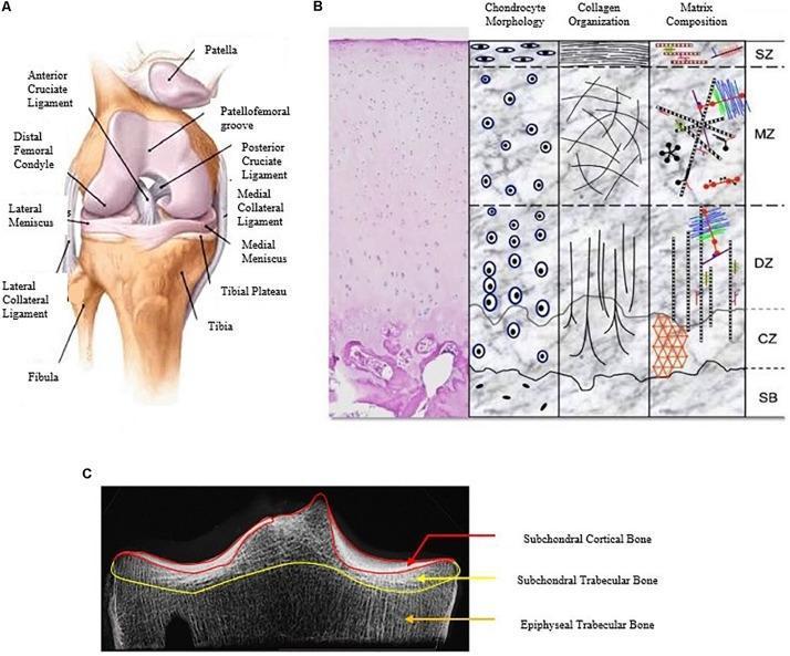
Anterior view of the knee joint showing femur, tibia, fibula, patella, cruciate and collateral ligaments, and menisci (left); with articular cartilage zone architecture (centre); and CT tibial plateau morphometry (right).
2. Normal Range of Motion
| Motion | Average Range (°) | Functional Range (°) |
|---|---|---|
| Flexion | 145 | 90 (117° to squat; 110° to rise from chair after TKA) |
| Extension | 0 to −3 (hyperextension) | 0 |
| Internal rotation (at 90° flexion) | 30 | — |
| External rotation (at 90° flexion) | 45 | — |
- A few degrees of passive axial rotation are possible at 30° of flexion
- Knee motion is complex due to a changing (polycentric) instant center of rotation
— Miller's Review of Orthopaedics 9th Edition, p. 123
3. Kinematics: The Four-Bar Linkage Model
Knee motion is classically modeled as a four-bar linkage system:
- The four bars are: ACL, PCL, femur (between femoral insertions), and tibia (between tibial insertions)
- The intersection of the cruciate ligaments defines the instantaneous center of joint rotation
- As the knee flexes, this center moves posteriorly, producing coupled rolling and gliding at the articular surfaces
Rolling vs. Sliding
| Type | Description |
|---|---|
| Pure rolling | Instant center at the rolling surface; no relative velocity at contact point |
| Pure sliding | Translation or rotation about a stationary axis; slipping of one surface on the other |
| Rolling + sliding | Normal knee behavior — a combination of both |
During flexion and extension, both rolling and sliding occur simultaneously. The instant center of rotation traces a J-shaped curve about the femoral condyle, moving posteriorly with flexion.
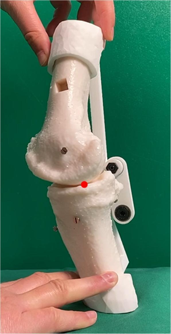
3D-printed knee model demonstrating the four-bar linkage (cruciate ligament analogue) externally constrained to simulate tibiofemoral contact point during rollback and kinematic assessment for TKA planning.
4. Posterior Femoral Rollback
- As the knee flexes, the tibiofemoral contact point moves posteriorly — this is posterior femoral rollback
- Rollback increases maximum knee flexion by preventing posterior impingement of the femoral condyle on the posterior tibial plateau
- Normal rollback requires an intact PCL
- In cruciate-sacrificing TKA, PCL sacrifice compromises rollback; this must be compensated by prosthetic cam-post mechanisms (see Section 8)
- Lateral femoral condyle rolls back more than the medial condyle
— Miller's Review of Orthopaedics 9th Edition, p. 123
5. The Screw-Home Mechanism: Locking & Unlocking
Locking (Terminal Extension — "Screwing Home")
- During the last 15° of extension, the femur rotates internally (or equivalently, the tibia rotates externally relative to the femur)
- This occurs because:
- The medial femoral condyle has a larger radius of curvature (longer articular arc) than the lateral condyle
- The medial condyle must travel a greater distance; the lateral condyle finishes its arc first, so the femur pivots internally about the medial condyle
- The axis of rotation of the intact knee lies in the medial femoral condyle
- This rotation "locks" the joint in extension, creating a close-packed position — maximally congruent, stabilised without muscle effort
- The anterior cruciate ligament tightens progressively as extension is completed
Clinical implication: The knee is most stable in full extension. Significant ligamentous and bony injury is required to disrupt a fully extended knee.
Unlocking (Initiation of Flexion — Popliteus)
- To initiate flexion from full extension, the screw-home must be reversed
- The popliteus muscle is the "unlocking" muscle
- It internally rotates the tibia (or externally rotates the femur on a fixed tibia) by ~5°
- This "unlocks" the joint from its close-packed position, allowing flexion to begin
- The popliteofibular ligament assists by providing additional posterolateral restraint during this phase
6. Meniscal Biomechanics
The menisci are crescent-shaped fibrocartilaginous structures composed primarily of type I collagen with fibres arranged:
- Circumferentially: to disperse hoop stresses (captured by vertical mattress sutures in repair)
- Radially: to resist longitudinal tearing
- Randomly at the surface: to disperse shear stresses from flexion
Load Transmission
| Condition | Load through menisci |
|---|---|
| Full extension | 50–75% of axial load |
| 90° of flexion | 85% of axial load |
| Medial meniscus | 30–40% of tibiofemoral load |
| Lateral meniscus | ~70% of tibiofemoral load |
- Menisci reduce peak contact stresses by 100–200%
- Resection of 75% of radial width produces contact stress increases equivalent to total meniscectomy
Meniscal Movement
- Menisci move anteriorly in extension and posteriorly in flexion
- Lateral meniscus excursion (~11 mm) is twice that of the medial meniscus (~5 mm) during a 120° arc
- The lateral meniscus has fewer soft-tissue attachments and is more mobile
- The posterior horn of the medial meniscus is a major secondary stabiliser against anterior tibial translation in ACL-deficient knees
— Miller's Review of Orthopaedics 9th Edition, p. 340
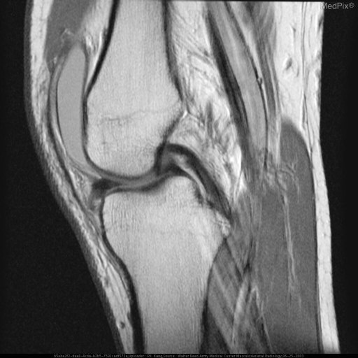
Sagittal MRI demonstrating the normal biconcave, low-signal meniscus positioned between femoral condyle and tibial plateau, with intact cruciate ligaments and infrapatellar fat pad.
7. Ligament Biomechanics
Ligaments provide passive restraints against abnormal motion. Their tensile strengths:
| Ligament | Tensile Strength |
|---|---|
| ACL | ~2200 N (up to 2500 N in young adults) |
| PCL | ~2500–3000 N |
| Superficial MCL | ~550 N |
| Deep MCL | ~100 N |
| POL | ~250 N |
| LCL | ~750 N |
- Ligaments anterior to the flexion axis stretch with flexion; those posterior shorten
- ACL experiences peak loads of 170 N during walking, up to 500 N with running
- Reconstructed grafts must be placed within the flexion axis to maintain isometry through the full arc of motion
Directional Stabilisers
| Direction | Primary Restraints |
|---|---|
| Medial | Superficial MCL (primary), joint capsule, medial meniscus, ACL/PCL |
| Lateral | Joint capsule, IT band, LCL, popliteus |
| Anterior | ACL (primary) |
| Posterior | PCL (primary) |
— Miller's Review of Orthopaedics 9th Edition, p. 340
8. Patellofemoral Biomechanics
- The patellofemoral joint has a sliding articulation
- The patella slides 7 cm caudally with full flexion
- The instant center of the patellofemoral joint is near the posterior cortex above the condyles
- The patella increases the mechanical advantage of the quadriceps by increasing the moment arm of the extensor mechanism
- At 90° of flexion, patellofemoral compressive forces reach 3–5× body weight (e.g., stair climbing)
- Maltracking of the patella is related to the Q-angle (normal: 10–15° in males, 15–20° in females)
9. Lower Extremity Axes — Relevance to Arthroplasty
| Axis | Description | Normal Value |
|---|---|---|
| Mechanical axis | Centre of femoral head to centre of ankle | Passes just medial to medial tibial spine |
| Anatomic axis of femur | Along femoral shaft | 6° valgus from mechanical axis |
| Mechanical axis vs. vertical | — | 3° valgus |
| Anatomic axis of tibia | Along tibial shaft | 2–3° varus from mechanical axis |
The femorotibial angle (anatomic) is ~6° valgus — the angle at which the tibial and femoral anatomic axes intersect.
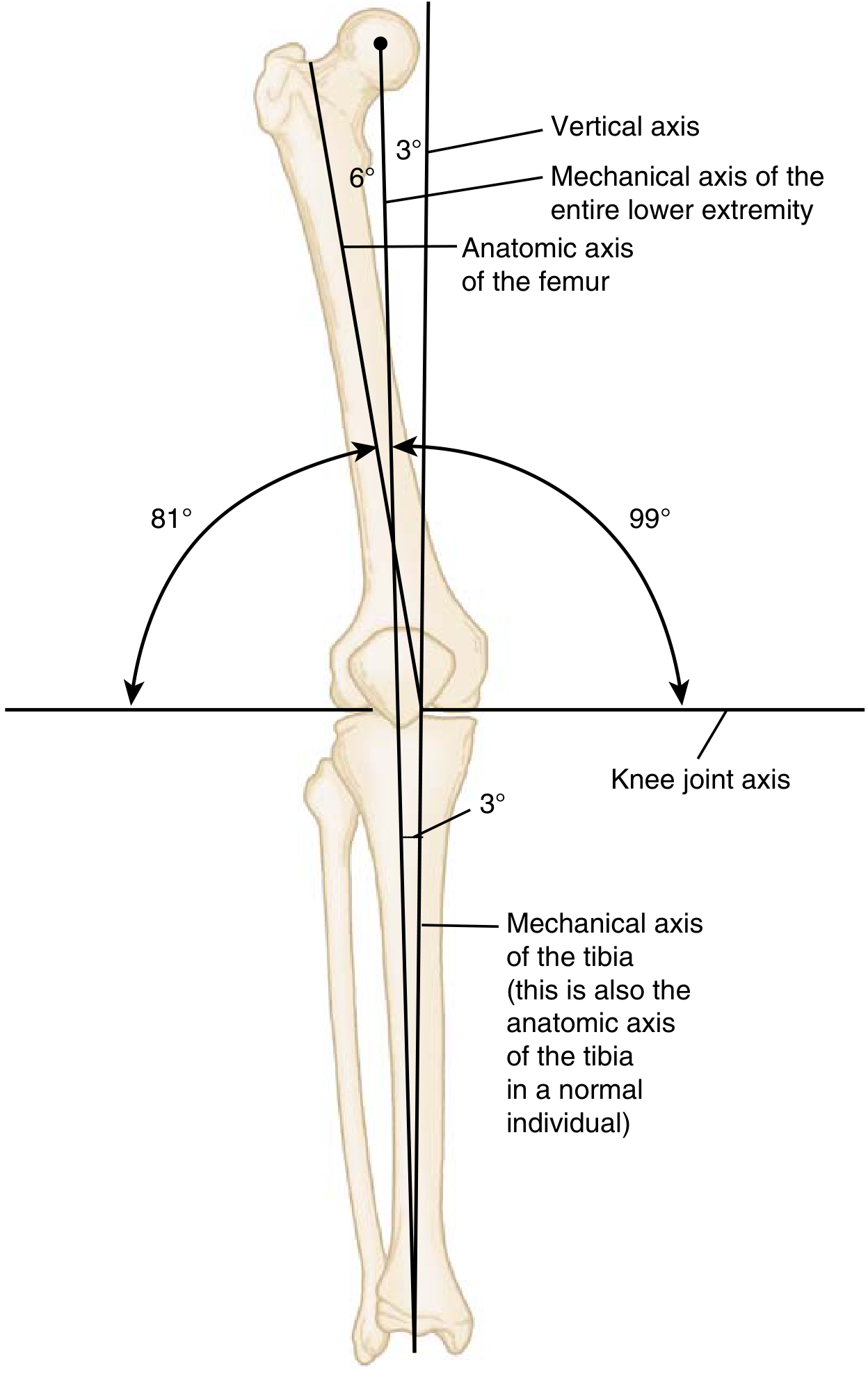
Mechanical and anatomic axes of the lower extremity — critical reference for TKA component alignment.
10. Application in Total Knee Arthroplasty (TKA)
Biomechanical Goals of TKA
- Restore the mechanical axis — neutral alignment (0° of the mechanical axis through the joint centre)
- Restore joint line — mismatch alters PCL tension, gap balance, and patellar tracking
- Balanced flexion-extension gaps — symmetric gaps avoid laxity and prevent polyethylene wear
- Restore posterior condylar offset — maintains flexion and rollback
Component Design and PCL Management
| Design | PCL Status | Rollback Mechanism |
|---|---|---|
| Cruciate-retaining (CR) | PCL preserved | PCL provides natural rollback |
| Posterior-stabilised (PS) | PCL sacrificed | Cam-post mechanism substitutes rollback |
| Ultra-congruent (UC) | PCL sacrificed | Articular geometry provides some restraint |
- Normal rollback is compromised by PCL sacrifice in cruciate-sacrificing TKA — the PS prosthetic cam-post mechanism replicates this function
- Functional range needed post-TKA: ≥90° for daily activities; ≥110° to rise from a chair
Rotational Alignment in TKA
Rotational alignment of femoral and tibial components is critical:
- Femoral component should be externally rotated 3° relative to the posterior condylar axis (parallel to the epicondylar axis and Whiteside's line)
- Tibial component should be rotationally aligned to the tibial tuberosity (medial third)
- Malrotation leads to patellar maltracking, flexion instability, and accelerated polyethylene wear
To optimise patellar tracking, surgeons use the "no-thumb" test and aim for:
- Lateral placement of femoral and tibial components
- Medial placement of the patellar component
- Avoidance of tibial internal rotation
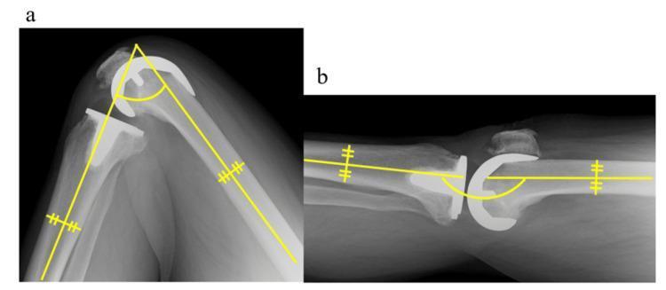
Sagittal radiographs of a TKA at maximum flexion (left) and maximum extension (right), with angular measurement overlays demonstrating femoro-tibial axis and component positioning.

11. Application in Knee Arthroscopy
Biomechanical Basis of Arthroscopic Decisions
Meniscal repair vs. resection: Biomechanics mandates preservation whenever possible:
- Total meniscectomy increases contact stresses by 100–200%
- Partial meniscectomy: even 75% radial width resection approximates total meniscectomy in stress effects
- The peripheral 20–30% of the medial meniscus and 10–25% of the lateral meniscus are vascularised — tears in the red-red zone have the highest healing potential and should be repaired
ACL reconstruction tunnel placement:
- Femoral tunnel must be placed at the anatomic footprint (posterior wall of the lateral femoral condyle) — isometric placement within the flexion-extension axis is critical
- Tibial tunnel should avoid roof impingement in extension
- Graft tensile strengths guide choice: patellar tendon graft ~2900 N; quadrupled hamstring ~4000 N
Screw-home and arthroscopy:
- Arthroscopy is typically performed in figure-of-four position or with knee at 70–90° flexion — after the popliteus has unlocked the knee
- Varus stress opens the medial compartment; valgus opens the lateral — exploiting natural tibiofemoral gap dynamics
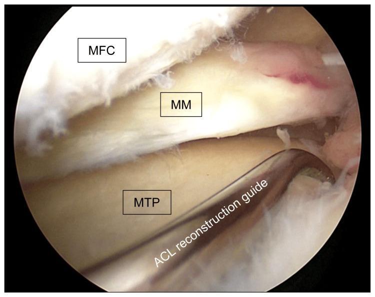
Intraoperative arthroscopic image of the medial compartment showing the medial femoral condyle (top), medial meniscus, and medial tibial plateau with an ACL reconstruction tibial guide in position.
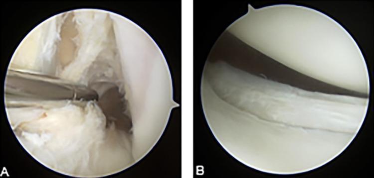
Arthroscopic images showing (A) complete ACL tear with disorganised fibres and (B) vertical full-thickness tear of the posterior horn of the lateral meniscus.
Summary Table: Key Biomechanical Concepts
| Concept | Key Detail |
|---|---|
| Joint type | Modified hinge (polycentric rotation) |
| Instant centre | J-shaped path, moves posterior with flexion |
| Four-bar linkage | ACL + PCL + femur + tibia |
| Screw-home locking | Femoral internal rotation in last 15° of extension |
| Unlocking muscle | Popliteus (internal tibial rotation) |
| Axis of rotation | Medial femoral condyle |
| Menisci load sharing | 50–75% in extension; 85% at 90° flexion |
| Posterior rollback | PCL-dependent; cam-post substitutes in PS-TKA |
| Patella excursion | 7 cm caudally in full flexion |
| Mechanical axis | 3° valgus from vertical |
| TKA functional ROM | ≥90° ADLs; ≥110° rising from chair |
— Miller's Review of Orthopaedics 9th Edition, pp. 123, 340
This is a shared conversation. Sign in to Orris to start your own chat.