
Blow in blow out orbital fractures in detail according to standard ENT textbook and subconjuctival approaches to treat orbital floor fractures in simplified manner
orbital blow-out fracture CT scan coronal orbital floor
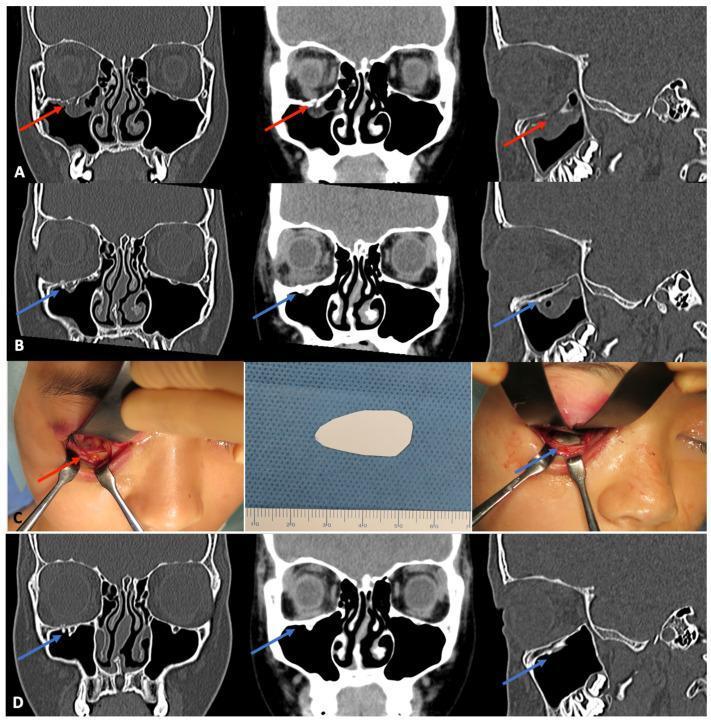
This composite educational image illustrates navigation-assisted reconstruction of an orbital floor blow-out fracture using bioactive u-HA/PLLA composite materials. (A) Preoperative CT scans in coronal and sagittal planes demonstrate a right orbital floor fracture with subsequent herniation of orbital fat and inferior rectus muscle into the maxillary sinus (indicated by red arrows). (B) Immediate postoperative CT scans show the placement of a radio-opaque u-HA/PLLA sheet (blue arrows) across the defect, successfully repositioning the orbital contents and restoring the anatomical floor. (C) Clinical photographs provide an intraoperative view of the surgical site, including a closeup of the blowout fracture, the pre-shaped composite sheet, and the final stabilized implant before closure. (D) A one-year follow-up CT scan confirms stable healing of the orbital floor. The u-HA/PLLA sheet remains visible and intact (blue arrows), with no evidence of recurrent prolapse or significant inflammatory tissue response. The sequence demonstrates a successful application of bioresorbable osteoconductive technology in maxillofacial trauma management.
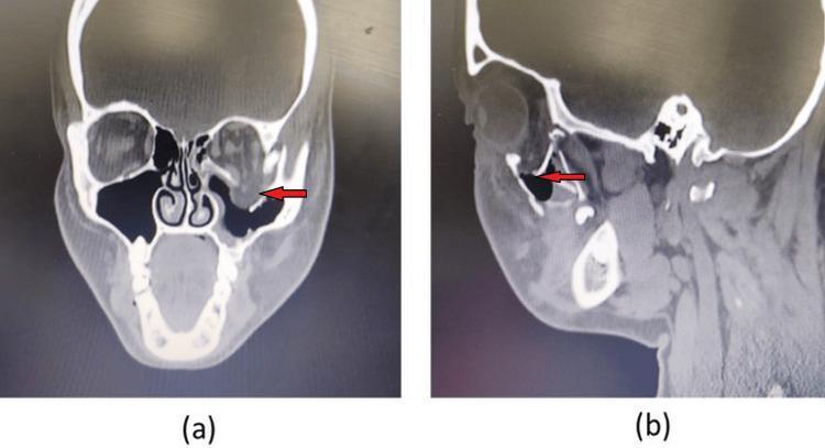
This diagnostic image displays a preoperative non-contrast CT scan of the maxillofacial region in coronal (a) and sagittal (b) views, illustrating a blow-out fracture of the left orbital floor. In the coronal section, a clear discontinuity of the inferior orbital wall is visible (indicated by a red arrow), with subsequent inferior herniation of orbital soft tissue—likely comprising orbital fat and the inferior rectus muscle—into the superior aspect of the left maxillary sinus. This finding is characteristic of a trapdoor or hydraulic-type fracture following periorbital trauma. The sagittal view further delineates the anteroposterior extent of the bony defect along the orbital floor and highlights the disruption of the normal anatomical boundary between the orbit and the underlying sinus. These images are clinically significant for diagnosing enophthalmos and potential extraocular muscle entrapment, providing essential anatomical mapping for surgical planning, such as open reduction and internal fixation with orbital mesh reconstruction.
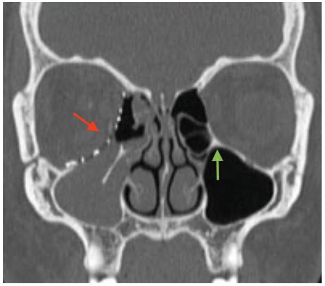
This coronal CT scan (bone window) demonstrates a postoperative view of a patient following the repair of a right orbital blow-out fracture. The image highlights the internal orbital buttress (IOB), a critical anatomical landmark at the junction of the medial orbital wall and orbital floor. The left orbit displays a normal, intact IOB (green arrow), providing typical structural support. On the right side, the native IOB is absent due to trauma. A single, large hyperdense orbital implant (red arrow) is visible, spanning both the medial wall and orbital floor to reconstruct the defect. Opacification of the right maxillary sinus is noted, likely representing postoperative blood or inflammatory fluid. This diagnostic image illustrates the surgical management of complex orbital fractures when the internal orbital buttress is compromised, necessitating a large-scale prosthetic reconstruction to restore orbital volume and support the ocular globe.
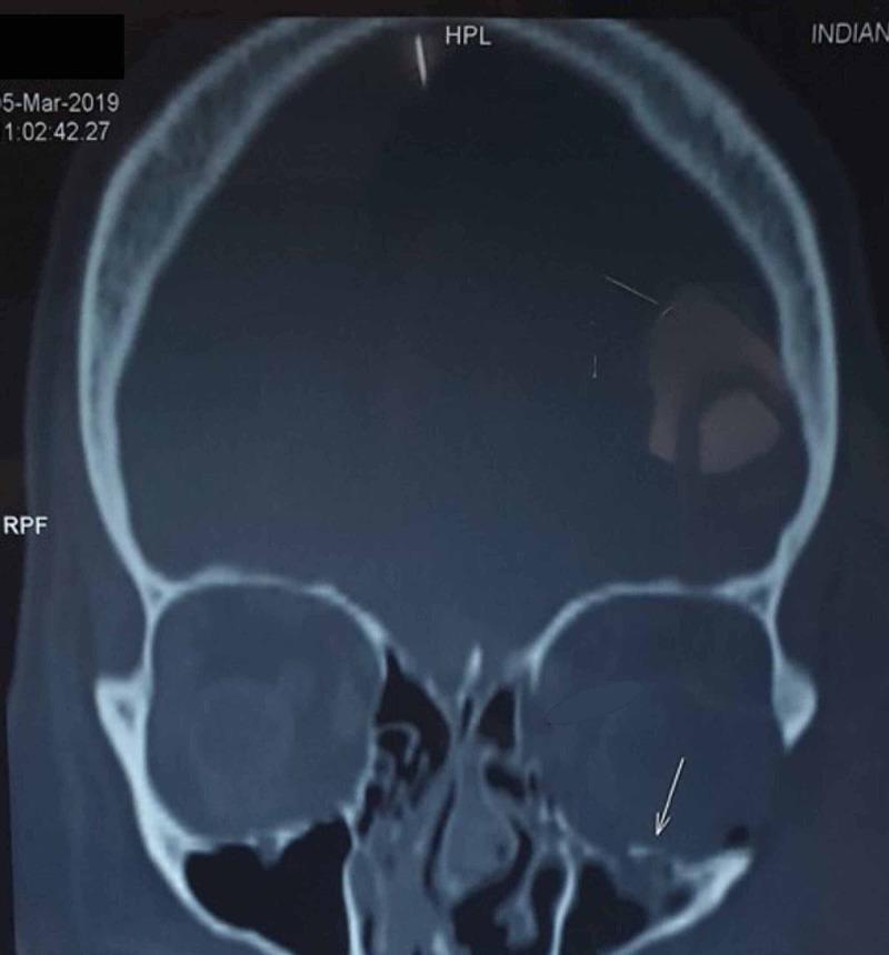
A preoperative non-contrast CT scan of the head in a coronal view, utilizing a bone window setting to visualize the facial and cranial structures. The image highlights a significant blow-out fracture of the left orbital floor (inferior wall). A clear discontinuity and downward displacement of the bony orbital floor are visible, indicated by a white arrow. This fracture results in the herniation of intraorbital soft tissue and periorbital fat into the superior portion of the left maxillary sinus, which appears partially opacified compared to the air-filled (black) right maxillary sinus. The right orbit and surrounding midface structures remain intact. This diagnostic image demonstrates the classic radiological presentation of a traumatic orbital floor fracture, often associated with entrapment of the inferior rectus muscle or orbital fat, necessitating surgical reconstruction to restore orbital volume and prevent enophthalmos.
Orbital Fractures: Blow-In and Blow-Out - A Comprehensive ENT Review
1. ANATOMY RELEVANT TO ORBITAL FRACTURES
- The orbital plate of the maxilla (posteromedial portion - the weakest point)
- The orbital plate of the zygoma (anterolateral)
- The orbital process of the palatine bone (posterior)
2. CLASSIFICATION OF ORBITAL FRACTURES
Pure vs. Impure Fractures
| Type | Definition |
|---|---|
| Pure fracture | Orbital wall fractured with intact orbital rim |
| Impure fracture | Orbital wall fracture involving the orbital rim (usually from zygomaticomaxillary complex fractures) |
Blow-Out Fracture (Pure)
-
Hydraulic (Globe-to-Wall) Theory (Smith and Converse, 1956 cadaveric study):
- Blunt trauma by an object smaller in diameter than the orbit pushes orbital contents posteriorly
- Resultant sudden increase in intraorbital pressure causes fracture at the weakest point = posteromedial orbital floor
- Floor "blows out" into the maxillary sinus
- Classic: fist, tennis ball, squash ball
-
Buckling Theory:
- Direct blow to the orbital rim causes the rim to buckle
- Force transmitted along the orbital floor causes fracture at its weakest point
- No direct pressure on the globe required
Blow-In Fracture
- Direct trauma to the orbital rim drives bone fragments into the orbit (rather than outward into the sinus)
- Volume of the orbit is reduced
- Presents with exophthalmos (not enophthalmos)
- For orbital roof: the "impure" blow-in fracture involving roof + rim is the most commonly encountered type of roof fracture (KJ Lee)
- May directly compress or threaten the globe and optic nerve
3. CT SCAN FINDINGS
4. CLINICAL PRESENTATION
Symptoms
- Pain (especially on eye movement)
- Blurred vision
- Binocular vertical or oblique diplopia (most commonly on upgaze)
Signs of Periocular Injury
- Eyelid edema and ecchymosis (periorbital bruising)
- Subcutaneous or orbital emphysema (air crepitus - from air entering orbit from maxillary sinus)
- Subconjunctival hemorrhage
- Enophthalmos (in blow-out - orbital volume expansion) or exophthalmos (early, from soft tissue swelling)
- Globe ptosis (hypoglobus - inferior displacement of globe)
- Infraorbital nerve hypoesthesia - cheek, lower lid, side of nose, upper lip, upper teeth and gums (fracture involving infraorbital canal) - Kanski
Ocular Injuries Associated
- Corneal abrasion
- Traumatic iritis (photophobia, blurred vision, brow ache)
- Hyphema (layer of blood in anterior chamber)
- Lens dislocation / subluxation
- Vitreous hemorrhage
- Retinal detachment (acute, painless loss of vision with flashes and field defect)
- Commotio retinae - outer retinal layer injury from shockwave; macular involvement causes blur
- Open globe injury
Motility Defects
Trapdoor Fracture (KJ Lee) - Clinically important!
- Small floor fracture where a flap of bone momentarily opens, orbital soft tissue protrudes through, bone recoils faster than soft tissue → tissue trapped in defect
- Greatest restriction in upgaze
- Associated vagal symptoms: nausea, vomiting, bradycardia (oculocardiac reflex)
- Can cause ischemia to extraocular muscles (EOM) and subsequent fibrosis + restrictive strabismus
- Most common in children due to more flexible (greenstick) bones
"White-Eye" Blow-Out Fracture (Bailey & Love)
- Seen in children with trapdoor defect
- No subconjunctival hemorrhage despite entrapped muscle
- May present with oculocardiac reflex (bradycardia, nausea, syncope)
- Treat as an emergency - irreversible muscle necrosis can occur within hours
- On CT: floor appears undisplaced or minimally displaced (trap has opened and closed)
Retrobulbar Hemorrhage
- Can cause orbital compartment syndrome: proptosis, pain, loss of vision, and frozen globe (complete EOM restriction)
5. EVALUATION
Basic Examination (KJ Lee protocol)
- Visual acuity - assessed one eye at a time with near card
- Pupillary examination - afferent pupillary defect, anisocoria, peaked/irregular pupil
- Intraocular pressure (Tonopen)
- Motility assessment - attention to upgaze (entrapment)
- Diplopia fields: have patient follow finger horizontally and vertically
- IOP increase of 1-15 mmHg on upgaze vs. primary position = suggests inferior rectus entrapment
- Cranial nerve assessment (III, IV, V, VI, VII)
- Slit lamp and dilated fundoscopy
- Exophthalmometry
Forced Duction Test
- Distinguishes paretic from entrapped (restricted) muscle
- Fine-toothed forceps (0.5 mm) grab tissue at limbus after topical anaesthetic
- Patient looks in direction of limited gaze
- Resistance encountered on passive globe movement = positive = entrapment
- Performed at start and end of any surgical case
Imaging
- CT scan is the gold standard - coronal and axial views
- Shows floor defect, herniation of orbital contents, degree of displacement
- Helps plan timing and approach of surgery
6. MANAGEMENT
Conservative Management
- Nasal precautions: avoid nose blowing, sneezing with closed mouth, sucking through a straw
- Prophylactic antibiotics (given communication with maxillary sinus)
- Ice packs, head elevation
Indications for Surgery (Dutton's Guidelines - KJ Lee)
| Indication | Detail |
|---|---|
| Persistent diplopia | Positive forced ductions + CT evidence of entrapment + no improvement over 1-2 weeks |
| Early enophthalmos | ≥ 3 mm |
| Significant globe ptosis | Hypoglobus |
| Large floor defect | > 50% of floor likely to result in late enophthalmos |
| Associated rim/facial fractures | Impure fractures |
Additional Indications (KJ Lee)
- Blow-in fracture: bone fragments may compromise vision
- Persistent diplopia interfering with occupation (pilots, mechanics, painters, professional athletes)
- Vagal signs (oculocardiac reflex): intractable nausea, vomiting, bradycardia = emergent decompression
- Herniation of globe into maxillary sinus = emergent repair
- Progressive findings
Timing of Surgery (KJ Lee)
- Observe for 7-10 days to allow edema and hemorrhage to resolve
- Preferably repaired within 2 weeks of injury
- Injuries >6 weeks become increasingly difficult to repair
- Delayed repair → persistent enophthalmos from fibrosis and contracture of orbital soft tissue
- Exception: trapdoor fractures with oculocardiac reflex or muscle ischemia = immediate emergency surgery
7. SURGICAL APPROACHES TO THE ORBITAL FLOOR
Approaches Comparison
| Feature | Subciliary (Transcutaneous) | Transconjunctival (Subconjunctival) |
|---|---|---|
| Incision location | Skin 2 mm below lash line | Conjunctiva below tarsus / in fornix |
| Scar | Visible skin scar | No visible scar |
| Ectropion risk | Higher | Lower |
| Exposure | Good | Good (comparable) |
| Preference | Older technique | Currently preferred |
8. TRANSCONJUNCTIVAL (SUBCONJUNCTIVAL) APPROACH - STEP BY STEP
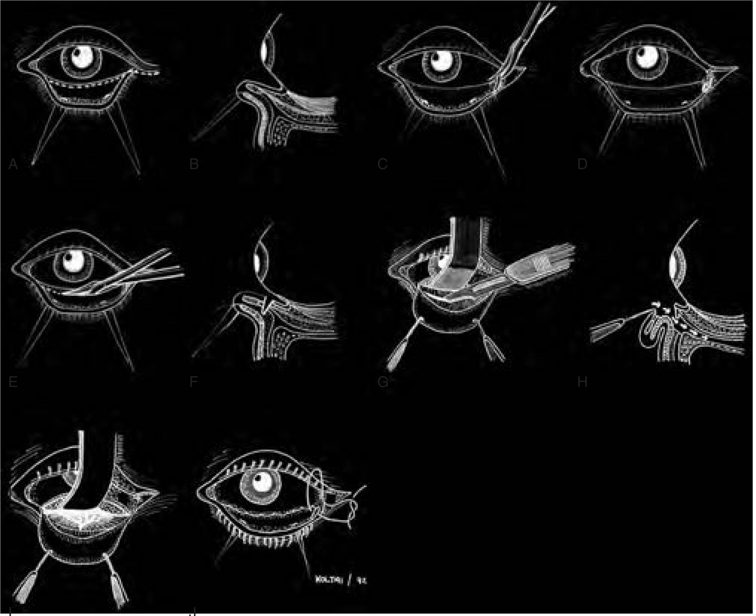
Step-by-Step Procedure (KJ Lee)
- General anesthesia
- Forced duction test performed at the beginning of the case
- A traction suture (e.g., 4-0 silk) is placed in the lower lid
- A Jaeger plate is used to protect the globe and provide gentle retraction as the lower lid is retracted by the traction suture
- Monopolar cautery with Colorado needle is used to make a conjunctival incision below the tarsus, from the punctum to the lateral canthus
- A lateral canthotomy and inferior cantholysis may be added to increase visibility and exposure
- A second traction suture is placed through the conjunctiva and retractors (now disinserted from tarsus); a heavy hemostat provides upward traction on the flap, pulling it over the cornea
- Desmarres retractor is placed in the lower lid to retract downward
- Dissection is continued in the preseptal plane to the orbital floor
- The periorbita (periosteum) is incised with monopolar cautery
- Periorbita is elevated with a periosteal elevator
- Periorbital elevation is continued posteriorly
- Malleable retractors retract orbital contents as the surgeon uses a Freer elevator in one hand and suction in the other to continue periosteal elevation to the anterior edge of the fracture
-
All edges of the fracture are identified
-
Prolapsed orbital content is reposited into the orbit
-
Various implant materials are available for floor fracture repair:
- Preferred by KJ Lee authors: thinnest Supramid available (0.1-0.4 mm)
- Other options: titanium mesh, porous polyethylene, resorbable sheets (e.g., u-HA/PLLA)
- Kanski: repair performed with elevation of periosteum from orbital floor, freeing trapped orbital contents, and covering defect
-
Implant shaping: Cut in the shape of a "guitar pick" and placed to cover the floor defect; trimmed as needed
-
Fixation: Some surgeons fixate; KJ Lee authors find it unnecessary for isolated floor fractures
- Alternatively: two small parallel incisions in the central anterior edge of implant with central portion depressed and wedged into the anterior edge of the defect for stability
- Forced ductions are repeated to ensure no additional restriction
- Periosteum closed with 4-0 Vicryl sutures (interrupted)
- If canthotomy/cantholysis performed: lateral canthal tendon reattached with 4-0 Vicryl
- Conjunctiva approximated (with fast-absorbing plain gut suture - though not always necessary per Cummings/Koltai)
9. PRESEPTAL vs. POSTSEPTAL DISSECTION PLANES
| Plane | Description | Notes |
|---|---|---|
| Preseptal | Dissection anterior to the orbital septum | Less risk of fat prolapse, preferred by most |
| Postseptal | Posterior to orbital septum, through preseptal fat | Direct path to floor; fat may prolapse and obscure field |
10. IMPLANT MATERIALS
| Material | Notes |
|---|---|
| Supramid (nylon) | Thin (0.1-0.4 mm), non-absorbable; preferred by KJ Lee for isolated floor fractures |
| Porous polyethylene (Medpor) | Good for larger defects; allows tissue ingrowth |
| Porous polyethylene + titanium | Preferred for combined floor + medial wall fractures (KJ Lee) |
| Titanium mesh | Strong, contourable, radiopaque |
| Resorbable sheets (PDS, u-HA/PLLA) | Used in pediatric patients to avoid growth disturbance |
Note for medial wall fractures: Implant fixation is mandatory (not optional as in isolated floor fractures), and implants must be fixed posterior to the orbital rim, not to the anterior rim.
11. COMPLICATIONS OF ORBITAL FLOOR REPAIR
- Diplopia (persistent or new onset)
- Enophthalmos (inadequate repair or implant migration)
- Implant infection or extrusion
- Lower lid ectropion (especially with subciliary approach)
- Infraorbital nerve hypoesthesia (injury or persistent)
- CSF rhinorrhea (if skull base compromised)
- Retrobulbar hemorrhage
- Loss of vision (optic nerve injury)
- Telecanthus (if medial canthal tendon not addressed)
12. SPECIAL SITUATIONS
Orbital Roof Fractures (Blow-In Pattern, KJ Lee)
- Less common; 3-9.3% of all facial fractures involve orbital roof; more common in children (18-35% of pediatric facial fractures)
- "Pure" = roof only; "Impure" = roof + rim; Impure blow-in is the most common type of roof fracture
- Children have proportionally larger cranium and thinner supraorbital bone
- Signs: upper eyelid hematoma with delayed expansion, forehead hypoesthesia, contour deformity, CSF rhinorrhea, neurologic deficits, pulsatile proptosis (from prolapsed intracranial contents)
- Management: Interdisciplinary - ENT + Neurosurgery + Ophthalmology
- Intracranial injury takes precedence
- Nondisplaced: observe (but monitor for pulsatile proptosis)
- Displaced with visible contour deformity: reduction + fixation
- CSF leak: observe 1 week for spontaneous resolution; if persistent → dural repair
Summary Table: Blow-Out vs. Blow-In
| Feature | Blow-Out Fracture | Blow-In Fracture |
|---|---|---|
| Orbital rim | Intact | Usually fractured (impure) |
| Direction of fragment | Into maxillary sinus (downward) | Into orbit |
| Orbital volume | Increased | Decreased |
| Globe position | Enophthalmos | Exophthalmos |
| Mechanism | Hydraulic/buckling via indirect globe pressure | Direct rim trauma |
| Common site | Orbital floor (posteromedial) | Orbital roof (most common) |
| Management | Repair floor, reposition orbital contents | Decompression, fragment removal; neurosurgery if roof |
- KJ Lee's Essential Otolaryngology, Chapter 57: Orbital Fractures (primary ENT textbook reference)
- Kanski's Clinical Ophthalmology: A Systematic Approach, 10th ed., Chapter 22: Orbital Floor Blow-Out Fracture
- Bailey and Love's Short Practice of Surgery, 28th ed., Chapter 31: Orbital Fractures
- Cummings Otolaryngology Head and Neck Surgery, Fig. 191.7: Transconjunctival Approach
- Scott-Brown's Otorhinolaryngology Head & Neck Surgery