
Periumbilical pain (referred from midgut organs).
periumbilical referred pain midgut organs visceral pain diagram
Explain this to me in simplest language possible
referred pain diagram midgut organs periumbilical
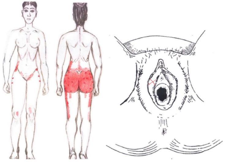
This medical illustration presents a graphical simulation of referred pain patterns associated with the gluteus medius muscle in a female subject. The image consists of two primary components: anatomical body maps (anterior and posterior views) and a detailed perineal diagram. On the body maps, referred pain is indicated by red shaded regions and 'x' markers. Posteriorly, the pain is concentrated over the gluteal region, extending superiorly to the iliac crest and inferiorly along the posterior and lateral thigh. Anteriorly, pain zones are mapped to the inguinal area, the lateral hip (greater trochanter region), and the anterior-medial knee. A detailed anatomical diagram of the vulva on the right includes an 'x' mark superior to the vaginal orifice, specifically localized near the clitoris and labia minora, highlighting the clinical relevance of myofascial trigger points in the pelvic and gluteal muscles to referred urogenital and lower extremity pain. This resource is intended for physical therapy and musculoskeletal educational indexing.
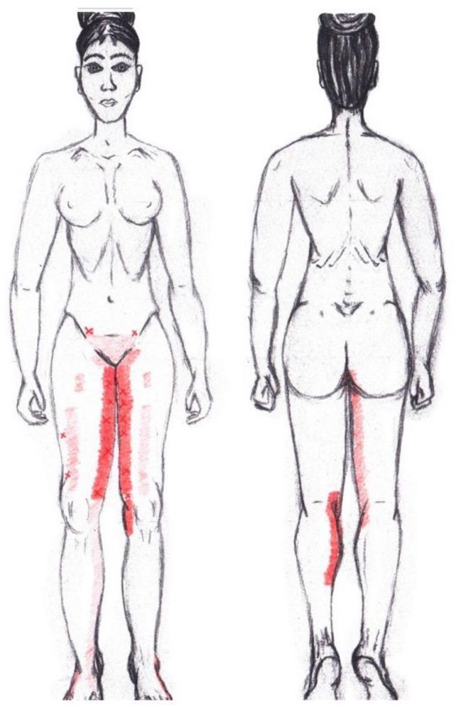
This medical illustration is a graphical simulation of myofascial referred pain patterns associated with the adductor magnus muscle, presented on a female body schematic in anterior and posterior views. The diagram uses red color mapping to indicate pain distribution and frequency. In the anterior view, primary referred pain is depicted as intense, vertical red bands along the bilateral medial thighs, extending from the groin to the superior aspect of the knees. Faint red patches and 'X' markers on the lateral and superior thighs indicate areas of less frequent or secondary referred pain. In the posterior view, the simulation identifies a significant referred pain area on the superior-medial aspect of the right calf. The color intensity serves as a semi-quantitative scale, where more vibrant red highlights common clinical trigger point referral zones. This educational visual is designed for physical therapy, anatomy education, and clinical diagnostic training related to musculoskeletal pain syndromes and pelvic floor dysfunction.
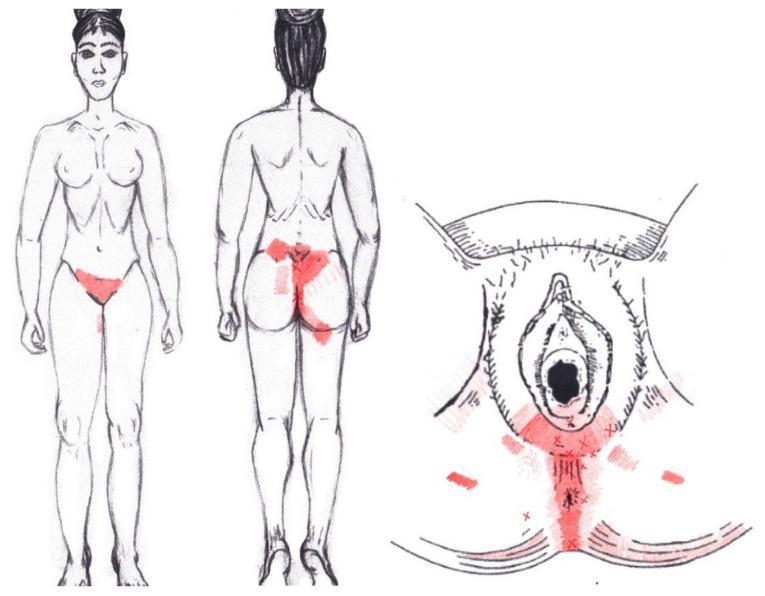
This medical illustration presents a graphical simulation of referred pain patterns associated with the coccygeus muscle in a female anatomical model. The visual includes three components: a full-body anterior view, a full-body posterior view, and a localized perineal diagram. Referred pain zones are indicated by red shading and 'X' markers, with color intensity reflecting the frequency of pain reported in clinical studies. On the anterior view, pain is primarily localized to the pubic and lower hypogastric regions. The posterior view demonstrates significant referred pain across the sacral region, gluteal area (buttocks), and extending toward the upper posterior thighs. The detailed perineal diagram shows pain distribution along the midline from the vulva to the anus, with additional lateral involvement near the ischial tuberosities. This educational material is designed for pelvic health education, illustrating how coccygeus muscle dysfunction can manifest as somatic pain in the urogenital and pelvic floor regions.
Why Does Midgut Pain Feel Around the Belly Button?
1. What is the "midgut"?
| Section | Organs included | Where pain is felt |
|---|---|---|
| Foregut | Stomach, liver, gallbladder, pancreas | Upper abdomen (epigastrium) |
| Midgut | Small intestine, appendix, first half of large intestine | Around the belly button (periumbilical) |
| Hindgut | Second half of large intestine, rectum | Lower abdomen (suprapubic) |
2. Why doesn't the pain feel exactly where the problem is?
- When you cut your finger, your brain knows exactly where it hurts -- because skin pain nerves are very specific.
- When an organ hurts (like your appendix or intestine), the pain signals travel through a different, less precise nerve system. Your brain can't pinpoint the exact location -- it just knows "somewhere in the belly button area."
3. The nerve pathway (in simple terms)
4. The classic real-life example: Appendicitis
- The appendix is inflamed but only its own nerves (visceral/midgut nerves) are activated.
- Pain is felt as a vague, dull ache around the belly button.
- It's not sharp, and it's hard to point to exactly.
- The inflammation spreads to the lining of the abdominal wall (parietal peritoneum), which has very precise somatic nerves.
- Pain moves to the right lower abdomen (McBurney's point) and becomes sharp and localised.
- This shift in pain is a diagnostic clue doctors look for.
5. The key takeaway
Midgut organs (appendix, small bowel, part of the colon) can't send a "GPS signal" to your brain. Instead, all pain from these organs is sent to the belly button region because of shared nerve pathways from their embryological origin.
Explain why Gastric ulcer is more commonly found along the lesser curvature of the stomach Explain this to me in simplest language possible
Explain why Gastric ulcer is more commonly found along the lesser curvature of the stomach Explain this to me in simplest language possible
gastric ulcer lesser curvature stomach anatomy diagram
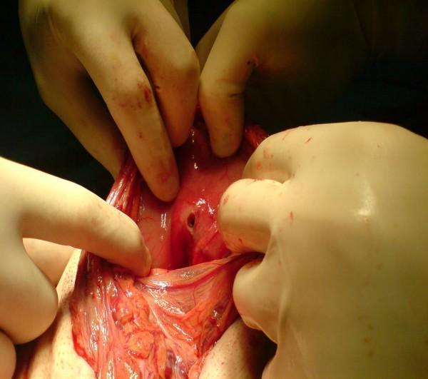
This intraoperative clinical photograph captures a surgical procedure during an exploratory laparotomy, demonstrating a perforated peptic ulcer. The image focuses on the stomach's lesser curvature, specifically the posterior pre-pyloric region. Gloved hands of the surgical team are seen retracting the surrounding tissues to expose a well-defined, circular perforation approximately 5-8 mm in diameter within an area of erythematous and inflamed gastric mucosa. The surrounding serosa and adjacent lesser omentum appear hyperemic with visible vasculature. The surgical field includes small amounts of blood and serosanguinous fluid, consistent with acute peritonitis. This visual provides clinical evidence of synchronous perforated ulcers, a rare but critical finding in emergency gastrointestinal surgery. It serves as a pedagogical resource for identifying visceral perforation and understanding the surgical anatomy of the lesser sac and gastric curvature.
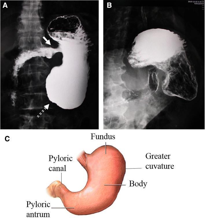
This composite figure presents a double-contrast upper gastrointestinal series compared to normal gastric anatomy, demonstrating significant structural distortion. Panel A shows a contrast-enhanced stomach with a shortened long axis and an enlarged distal antrum (dashed arrow), creating a distinctive 'hammer' shape. The pylorus is malpositioned, opening abnormally toward the side of the lesser curvature (solid arrow). Fluid accumulation is evident within the gastric lumen. Panel B highlights the gastric mucosa using double-contrast technique, revealing a 'bilateral sign' along the lesser curvature characterized by a fixed, irregular contour and mucosal absence in the gastric antrum, suggestive of localized pathology such as a large ulcer. Panel C provides a labeled anatomical diagram of a normal stomach (fundus, body, greater curvature, pyloric antrum, and pyloric canal) for morphological comparison. These findings illustrate complex gastric dysmotility or congenital malformation (such as organoaxial volvulus or malrotation) and secondary mucosal lesions. The content is suitable for educational use in gastroenterology and radiology focusing on contrast imaging interpretation.
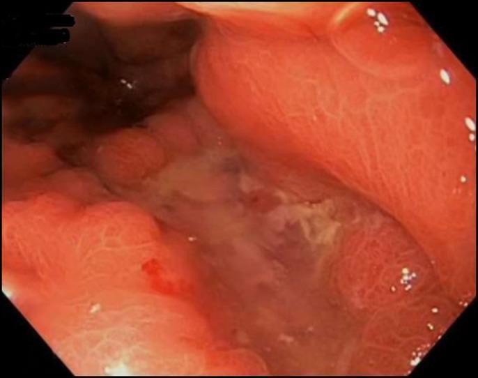
This endoscopic clinical photograph displays a large, cratered gastric ulcer located on the lesser curvature of the stomach. The lesion measures approximately 10 mm at its widest dimension and is characterized by a depressed, slough-covered base with whitish fibrinopurulent exudate. The ulcer edges are well-demarcated but notably irregular, with surrounding gastric mucosa appearing erythematous and nodular, suggesting significant localized inflammation and edema. No active spurting, oozing, or visible vessels (stigmata of recent hemorrhage) are observed within the ulcer bed, though minor punctate hemorrhage is visible on the peripheral margin. The surrounding vascular pattern of the gastric wall shows hyperemic changes consistent with underlying pathology, which in this clinical context was confirmed as adenocarcinoma with hepatoid features. This image serves as a teaching example for evaluating ulcer morphology and identifying the absence of high-risk bleeding stigmata during diagnostic upper gastrointestinal endoscopy.
Why Do Gastric Ulcers Form on the Lesser Curvature?
First, let's picture the stomach
- The lesser curvature = the short, inner curve (like the inside of a bent elbow)
- The greater curvature = the long, outer curve (like the outside of a bent elbow)
The answer comes down to 3 reasons:
Reason 1: It's the "Food Highway" -- gets the most traffic
- This means the lesser curvature is constantly being hit by food, acid, and digestive juices.
- More traffic = more wear and tear = more damage over time.
Think of it like a road that gets 10x more cars than any other road -- it develops potholes faster.
Reason 2: It's the weakest spot -- "Locus Minoris Resistentiae"
- The acid-producing zone (body of stomach) meets the non-acid-producing zone (antrum/lower stomach).
- This transition zone is a natural "weak point" in the stomach lining.
Reason 3: The protective mucus layer is weaker here
- A thick layer of mucus (like a protective coating)
- Good blood flow to keep the lining healthy
- Special chemicals called prostaglandins that help repair damage
Putting it all together: The Imbalance Model
| Attack Forces | Defense Forces |
|---|---|
| Stomach acid (HCl) | Mucus layer |
| Pepsin (digestive enzyme) | Blood flow to lining |
| H. pylori infection | Prostaglandins |
| NSAIDs, aspirin, smoking | Rapid cell repair |
The classic type of ulcer here: Type 1 Gastric Ulcer
Simple one-line summary
The lesser curvature is the stomach's busiest, most exposed, and structurally weakest zone -- so when anything damages the stomach lining, it gives way here first.
Explain why Fibula is more commonly used for bone grafting. Explain this to me in simplest language possible
fibula free flap bone graft reconstruction anatomy
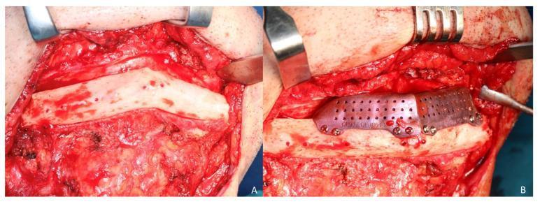
Clinical photograph of an intraoperative maxillofacial reconstruction procedure using a fibula free flap. Figure A shows the surgical exposure of a two-segment fibula flap via a cervical approach. The bone appears pale white with visible surface punctate bleeding, indicating healthy vascularization, and is surrounded by dissected cervical soft tissue and muscle. Figure B demonstrates the placement of a secondary cortico-cancellous iliac crest graft on top of the fibula segments to increase mandibular vertical height. The graft is secured using a custom CAD/CAM titanium mesh, which features a perforated design with 1.5 mm pores to facilitate tissue ingrowth and vascularization. The mesh is fixed to the underlying bone segments with several small diameter (1.5 mm) osteosynthesis screws. This image illustrates complex reconstructive surgery for mandibular defects, specifically addressing vertical discrepancy after primary fibula flap reconstruction.
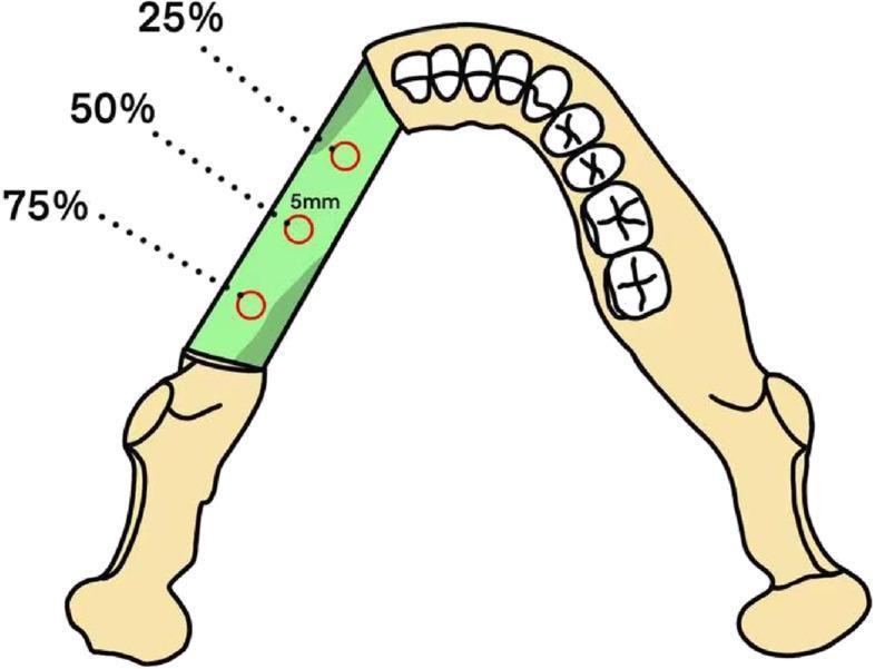
This medical anatomical diagram illustrates a fibula free flap graft integrated into a maxillary or mandibular arch for jaw reconstruction. The diagram shows a green-shaded segment representing the transplanted fibula bone flap positioned between existing segments of the jawbone, which include representations of the teeth and ramus. Three circular Regions of Interest (ROIs), each with a diameter of approximately 5 mm, are indicated along the longitudinal axis of the fibula graft. These ROIs are positioned at three distinct points: 25%, 50%, and 75% of the graft's total length. The illustration demonstrates the standardized methodology for measuring clinical parameters such as Hounsfield Unit (HU) values and Bone Mineral Density (BMD) to assess bone quality, graft integration, and potential resorption during post-operative follow-up. This visualization is intended for maxillofacial surgery and radiology education, highlighting the objective monitoring of reconstructive surgery outcomes.
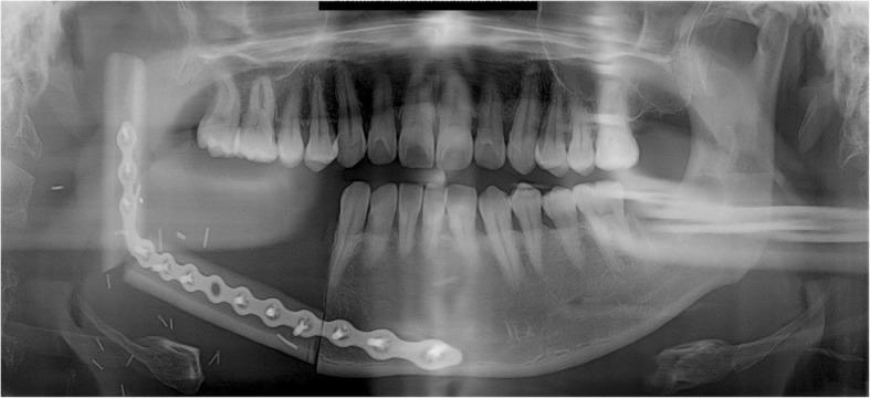
This panoramic radiograph (orthopantomogram) illustrates a postoperative view of a right mandibular reconstruction following resection. The primary reconstruction method utilizes a Fibular Free Flap (FFF), visible as a linear radiopaque bone graft extending from the right mandibular premolar region to the ascending ramus. The graft is secured by a long, contoured radiopaque reconstruction metal plate positioned along the inferior border of the mandible. The plate is fixed with multiple radiopaque cortical screws, bridging the junction between the native mandibular symphysis and the fibular graft. The fibula has been osteotomized and angled to mimic the natural mandibular contour and gonial angle. Superiorly, the reconstruction extends toward the glenoid fossa to replace the mandibular condyle. The contralateral (left) side shows intact mandibular anatomy and dentition. Key educational features include the visualization of microvascular bone flap integration, hardware placement for maxillofacial reconstruction, and the radiographic appearance of donor fibular bone used in mandibular oncology or trauma cases.
Why Is the Fibula Used Most Commonly for Bone Grafting?
First, what even is a bone graft?
Why the fibula wins -- 6 simple reasons
Reason 1: You don't need the fibula to walk
- The tibia -- the big, thick shin bone. This is the main weight-bearing bone. You absolutely need this.
- The fibula -- the thin bone on the outside of the leg. It carries only about 10% of your body weight.
Reason 2: It's long -- gives you a lot of bone to work with
Reason 3: It comes with its own blood supply (vascularized graft)
Think of it like transplanting a plant with its roots still intact versus just snapping off a branch. A graft with blood supply = living bone that can grow, heal, and adapt. A graft without blood supply = dead scaffolding that just fills a gap.
Reason 4: It is strong -- cortical (hard) bone
Reason 5: It can even bring soft tissue with it
Reason 6: The donor site heals well with low complications
- Can be closed directly
- Heals with relatively low morbidity
- Leaves the patient with full walking ability
Summary Table
| Feature | Fibula | Why it matters |
|---|---|---|
| Expendable bone | Yes -- only 10% weight bearing | You can remove it safely |
| Length available | Up to ~22 cm | Fills large defects |
| Blood supply | Peroneal artery | Living, healing bone |
| Bone type | Strong cortical bone | Structural support |
| Can bring skin | Yes | One-stop reconstruction |
| Donor site recovery | Good | Low complications |
The classic use case: Jaw reconstruction
One-line summary
The fibula is long, strong, has its own blood supply, and is completely expendable -- making it the perfect "spare part" to borrow without hurting the donor.
Same for why Saphenous vein is commonly used for CABG.
saphenous vein coronary artery bypass graft CABG diagram
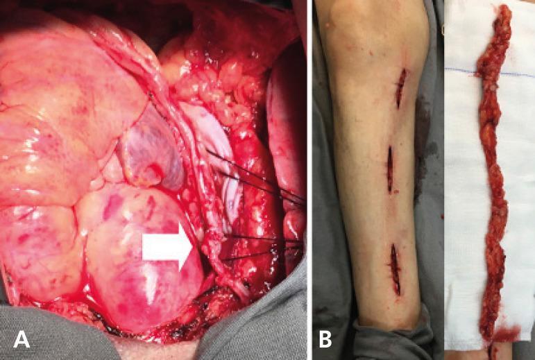
This composite clinical photograph illustrates key stages of a coronary artery bypass graft (CABG) surgery using a 'no-touch' saphenous vein (SV) harvesting technique. Panel A presents an intraoperative view of the surgical field during an off-pump coronary artery bypass (OPCAB). It shows a saphenous vein graft anastomosed to the posterior descending coronary artery, with a proximal connection to the right internal thoracic artery (RITA) stump, indicated by a white arrow. The vessels are secured with sutures, and the surrounding cardiac tissue and epicardial fat are visible. Panel B displays the donor site and the harvested conduit. The left side of the panel shows the lower extremity with three small, longitudinal incisions, characteristic of a minimally invasive, skin-bridging harvesting approach. The right side shows the harvested saphenous vein lying on a surgical gauze. The conduit is notable for its 'no-touch' appearance, characterized by an intact pedicle of perivascular adipose and connective tissue, which preserves the vessel's endothelial integrity and natural architecture by avoiding manual dilation or stripping.
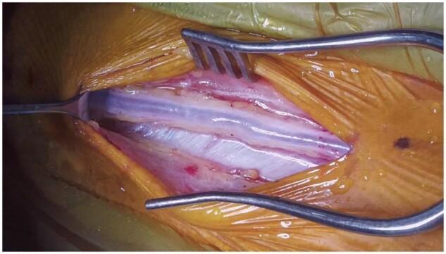
This clinical photograph captures a 'no-touch' saphenous vein graft (SVG) harvest during a surgical procedure, likely for coronary artery bypass grafting (CABG). The central focus is the saphenous vein, a long, bluish-white tubular structure characterized by a smooth surface with subtle longitudinal striations. Surrounding the vein is a generous margin of perivascular tissue (PVT), which appears pinkish, moist, and contains visible connective tissue strands and small vasa vasorum. This 'no-touch' technique preserves the PVT to improve long-term graft patency. The surgical field is exposed using stainless steel retractors; a self-retaining retractor with metal tines laterally displaces the skin and subcutaneous fat (covered by orange surgical drapes), while a blunt hand-held retractor provides further exposure on the left. The image illustrates careful surgical dissection designed to minimize direct trauma to the vessel wall by maintaining the native adventitia and surrounding fat.
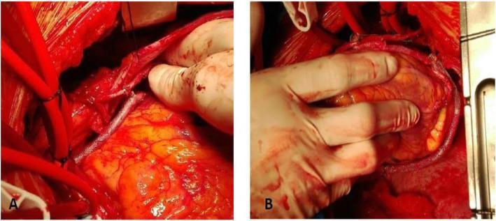
This clinical photograph consists of two panels (A and B) demonstrating intraoperative views of Coronary Artery Bypass Grafting (CABG) surgery using the VEST (Venous External Support Technology) system. In Panel A, a saphenous vein graft (SVG) is shown anastomosed to the posterior descending artery (PDA). The graft is encased in a cobalt-chrome mesh external stent, which provides structural support to the vein and is visible as a fine metallic sheath over the vessel. Several red surgical cannulas are visible in the left periphery. In Panel B, the surgeon's gloved hand is shown manipulating the epicardium to expose the ramus intermediate artery, where another stented SVG segment has been anastomosed. The heart's epicardial surface appears yellow due to subepicardial adipose tissue. These images illustrate the surgical application of external stents to saphenous vein grafts, intended to improve graft patency by reducing intimal hyperplasia and wall tension through mechanical stabilization of the conduit's diameter.
Why Is the Saphenous Vein Commonly Used for CABG?
First -- what is CABG and why do you need a graft?
Why the saphenous vein? -- 5 simple reasons
Reason 1: You don't need it -- it's expendable
- The deep veins (inside the leg, alongside the bones) -- the main highway. These carry ~90% of blood back from the leg.
- The superficial veins -- including the saphenous vein, running just under the skin.
Same logic as the fibula: it's a spare part the body already has a backup for.
Reason 2: It's the longest vein in the body -- plenty of material
- You can harvest multiple segments from a single harvest
- In triple or quadruple bypass surgery (3-4 blocked arteries to bypass), you still have enough material from one leg
Reason 3: It's the right size
Reason 4: It's easy to harvest
- Surgeons know exactly where to find it every time
- It can be harvested quickly through small incisions (even with minimally invasive "keyhole" techniques today)
- While one surgical team opens the chest, another team simultaneously harvests the vein -- saving operating time
Reason 5: It's your own tissue -- no rejection
But wait -- is it the best graft?
| Feature | Saphenous Vein | Internal Mammary Artery |
|---|---|---|
| Type | Vein (thin wall, lower pressure design) | Artery (built for high pressure) |
| 10-year patency | ~50-60% still open | ~90% still open |
| Preferred for | Multiple bypasses, when arteries aren't enough | Left anterior descending artery (LAD) bypass |
| Availability | Generous (long, two legs) | Limited (only two, one per side) |
- First choice: Use the internal mammary artery for the most important bypass (the LAD)
- Then: Use saphenous vein segments for any additional bypasses needed
Real-life intraoperative view
One-line summary
The saphenous vein is used because it's long, expendable, easy to harvest, the right size for coronary arteries, and available in large quantities -- making it the practical workhorse graft when multiple bypasses are needed.
Same for why Varicocele is more common on the left side.
varicocele left testicular vein anatomy drainage renal vein diagram
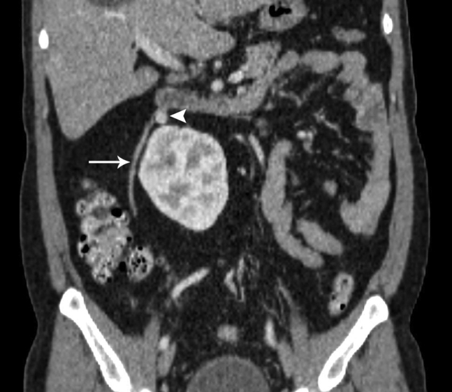
**Modality:** Contrast-enhanced Computed Tomography (CECT). **View:** Coronal reconstruction. **Anatomical Region:** Abdomen, specifically the retroperitoneum showing the renal and gonadal vasculature. **Key Findings:** - **Vascular Anatomy:** The image demonstrates a congenital vascular variation involving the right testicular (gonadal) vein. - **Anomalous Drainage:** The right testicular vein (indicated by the arrow) is seen ascending laterally to the inferior vena cava (IVC) and crossing medially to drain directly into the left renal vein (indicated by the arrowhead) instead of its typical insertion point into the anterolateral IVC. - **Landmarks:** Visible structures include the inferior pole of the liver, the right kidney, and the elongated left renal vein crossing the midline. **Diagnostic Significance:** This represents a rare anatomical variant of the gonadal venous system. Identification of such anomalies is clinically significant for preoperative planning in retroperitoneal surgeries, renal transplantation, and interventional radiological procedures such as varicocele embolization. **Search Terms:** CECT abdomen, coronal CT, anomalous right testicular vein, right gonadal vein variation, left renal vein drainage, retroperitoneal vascular anatomy.
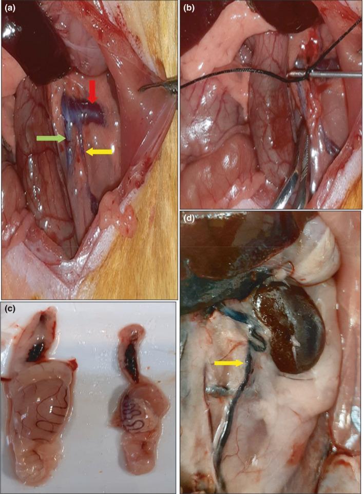
This composite of four clinical photographs illustrates the surgical induction and subsequent morphological effects of an experimental varicocele model in a rat, serving as a surrogate for human urological pathology. Panels (a) and (b) show the intra-abdominal surgical site: (a) demonstrates normal vascular anatomy including the left renal vein (red arrow), the left spermatic vein (yellow arrow), and the inferior vena cava (green arrow); (b) depicts the partial ligation of the left renal vein using a suture and metal probe to induce venous hypertension. Panel (c) presents a side-by-side comparison of dissected testes, showing significant testicular atrophy on the right (varicocele group) compared to the healthy control on the left. Panel (d) displays the resulting clinical manifestation in situ, specifically a distended and tortuous left internal spermatic vein (yellow arrow). The collection illustrates the pathophysiology of varicocele, highlighting the relationship between proximal venous obstruction, distal venous dilation (varicosity), and consequent testicular hypotrophy.
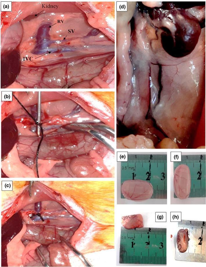
A multi-panel series of clinical photographs and gross specimens from an animal model study on varicocele. Panels (a) through (c) depict the surgical induction of varicocele via partial ligation of the left renal vein. Key anatomical landmarks labeled include the kidney, renal vein (RV), spermatic vein (SV), and inferior vena cava (IVC). Panel (b) illustrates the placement of a suture around the renal vein and a metal probe to ensure calibrated narrowing, while panel (c) shows the final surgical site after probe removal. Panel (d) displays a high-magnification clinical view of induced varicocele, characterized by a pale, dilated, and tortuous spermatic vein. Panels (e) through (h) compare excised testes measured against a ruler. Panels (e) and (f) show healthy control testes with normal morphology and size (~2 cm). Panels (g) and (h) demonstrate significant testicular atrophy in the varicocele group, with specimens appearing markedly smaller, shrunken, and discolored compared to the control group. The educational focus is on the anatomical pathways of venous drainage and the pathological progression of varicocele to testicular atrophy.
Why Is Varicocele More Common on the Left Side?
First -- what is a varicocele?
The key: how do the two sides drain differently?
| Side | Drains into | Angle of entry |
|---|---|---|
| Right testicular vein | Inferior vena cava (IVC) -- the body's largest vein | At an acute (oblique) angle -- like merging gently onto a highway |
| Left testicular vein | Left renal (kidney) vein | At a right angle (90°) -- like hitting a T-junction |
Why does the angle matter so much?
Plus -- the left vein is longer
It's like trying to pump water up a tall pipe that suddenly bends at 90° at the top -- it takes a lot more pressure, and fluid tends to pool at the bottom.
The result: Blood pools and veins dilate
- It backs up and pools in the pampiniform plexus (a network of small veins around the testicle inside the scrotum)
- The pressure causes these veins to dilate and become tortuous (twisted)
- This creates the swollen, "bag of worms" appearance of a varicocele
Why does this matter beyond just appearance?
Bonus: A clinical red flag
Visual summary
LEFT SIDE                          RIGHT SIDE
─────────────────                  ─────────────────
Testicular vein                    Testicular vein
     │                                  │
     │ (long journey up)                │ (shorter)
     │                                  │
     └──► Left Renal Vein              └──► IVC (directly)
          (90° angle = hard!)               (oblique angle = easy)

     ↑ Back pressure                   ↑ Flows freely
     ↑ Blood pools                     ↑ No pooling
     ↑ Varicocele forms                ↑ Rare varicocele
One-line summary
The left testicular vein is longer and drains at a sharp 90° angle into the renal vein -- creating back pressure that causes blood to pool and veins to balloon out into a varicocele.