
Direct vertebral rotation ms ortho 20 marks answer
Reading File
Now let me search the medical library and web simultaneously for comprehensive content on Direct Vertebral Rotation.
Finding Sources
Searching the Web
direct vertebral rotation DVR scoliosis surgical technique orthopedics
Excellent! Found the relevant section in Campbell's. Let me read it fully and also fetch the figures.
Reading File
Finding Sources
Let me read more of the relevant section and also search for scoliosis/DVR context around it.
Reading File
Finding Sources
Let me read the correction maneuvers section from block17 and continue reading DVR technique from block18.
Reading File
Reading File
Now let me read the full correction maneuvers section that includes DVR vs rod derotation.
Reading File
Loading Image
I now have excellent content from Campbell's Operative Orthopaedics plus the DVR technique figure. I have all the material needed to write a comprehensive 20-mark MS Ortho answer. Let me compile the full answer.
Direct Vertebral Rotation (DVR) - MS Orthopaedics (20 Marks)
Introduction
Scoliosis is a three-dimensional (3D) spinal deformity involving:
- Coronal plane - lateral curvature (measured by Cobb angle)
- Sagittal plane - abnormal kyphosis/lordosis
- Axial plane - vertebral rotation (the most difficult to correct)
Traditional surgical techniques like the Harrington distraction rod corrected only the coronal plane, leading to the "flatback deformity" and providing minimal axial rotation correction. The development of segmental pedicle screw fixation enabled true 3D correction, of which Direct Vertebral Rotation (DVR) is the most powerful method for axial plane deformity correction.
Definition
Direct Vertebral Rotation (DVR) is a surgical maneuver used in the correction of adolescent idiopathic scoliosis (AIS) in which screw derotators are applied directly to bilateral pedicle screws at the apical and juxta-apical vertebrae, and the vertebrae are physically rotated in the direction opposite to the deformity - achieving true 3D correction of the rotational component of scoliosis.
First described by Lee SM, Suk SI, and Chung ER (2004) in Spine, it was termed a "new technique of three-dimensional deformity correction with segmental pedicle screw fixation in adolescent idiopathic scoliosis."
Background and Rationale
Limitations of Prior Techniques
| Technique | Coronal | Sagittal | Axial (Rotation) |
|---|---|---|---|
| Harrington rod | Partial | Poor (flatback) | Minimal |
| Rod derotation (simple) | Good | Good | Indirect/limited |
| DVR | Good | Preserved | Direct and powerful |
Rod Derotation vs DVR
Simple Rod Derotation (SRD):
- Pre-contoured concave rod is connected to each fixation site
- Rod is rotated ~90 degrees into the sagittal plane
- This "converts scoliosis to kyphosis" - an en bloc derotation maneuver
- Results in lateral translation of apical vertebrae (indirect derotation)
- Two forces are generated: (1) posteriorly/medially directed vector; (2) rotation of the rod on its own axis
- Limited ability to directly correct intervertebral rotation
DVR:
- Acts directly on the vertebrae via screw derotators
- Corrects intervertebral rotation segment by segment
- Can be done en bloc (multiple levels simultaneously) or segmentally (individual levels)
- Opposite in direction to the rotational deformity
- Provides superior axial correction
Prerequisites for DVR
- Bilateral pedicle screws at every level to be fused in the thoracic spine (monoaxial or uniplanar screws)
- Knowledge of the direction of vertebral rotation at each level
- Screw derotators (special instruments)
- Intraoperative neuromonitoring (MEP - motor evoked potentials)
- Adequate mean arterial pressure (MAP ≥ 70 mmHg) to maintain spinal cord perfusion during correction maneuvers
Understanding the Direction of DVR
This is the most critical aspect of the technique.
In a Right Thoracic Curve (Lenke Type 1 - most common):
- Apical and juxta-apical thoracic vertebrae are rotated clockwise in the transverse plane (right rotation)
- DVR must be in the opposite direction - counterclockwise
- The rotation correction for the uppermost 1-2 vertebrae must also be opposite to the thoracic DVR
- For the lowermost 1-2 screws, DVR direction depends on the rotation of the compensatory lumbar curve
In a Double Major Curve:
- The lumbar DVR direction is opposite to the thoracic DVR direction
- The transitional vertebrae require careful assessment
Key Rule:
"The direction of DVR must be opposite to that of the vertebral rotation in the deformed curve."
Step-by-Step Surgical Technique (TECHNIQUE 40.14 - Campbell's)
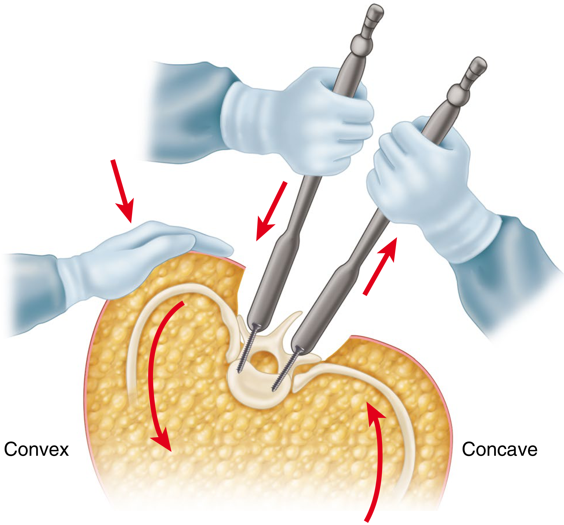
Step 1 - Pedicle Screw Insertion
- Insert bilateral pedicle screws at every level to be fused in the thoracic spine
- Identify the neutral (least rotated) vertebra distally - begin derotation proximal to this level
Step 2 - Neuromonitoring Setup
- Because of the corrective forces placed on the spine, a MAP of at least 70 mmHg is essential to maintain spinal cord perfusion
- Obtain a baseline motor-evoked potential (MEP) measurement before any reduction maneuver for comparison once maneuvers are complete
Step 3 - Apply Screw Derotators
- Insert screw derotators onto the pedicle screws of the juxta-apical vertebrae on both the concave and convex sides
Step 4 - Derotation Maneuver
- Derotate the vertebrae as much as possible in the direction opposite to the deformity
- This can be done in:
- En bloc fashion: multiple levels rotated simultaneously
- Segmental fashion: each individual level rotated one at a time
- Simultaneously:
- Push down on convex screws
- Pull up on concave screws
- An assistant should apply downward pressure on the convex apical ribs to aid derotation
Step 5 - Locking
- After completion of derotation, lock the rod into position by tightening set screws fully
- This process can be repeated multiple times until the desired correction is obtained
Step 6 - Completion
- If the curve is rigid, DVR may be limited - consider additional techniques like rod bending or apical posterior release
- Apply distraction/compression as needed for balance
- Perform decortication and bone grafting
- Close wound
Mechanisms of Correction
DVR achieves 3D correction through:
- Axial plane: Direct rotation of vertebra toward neutral - reduces apical vertebral rotation (AVR)
- Coronal plane: Derotation of rotated vertebrae assists in reducing the Cobb angle (coronal correction enhanced by DVR)
- Sagittal plane: En bloc DVR does not reduce thoracic kyphosis - it may even slightly increase kyphosis, which is beneficial in AIS patients who commonly have thoracic hypokyphosis
Advantages of DVR over Simple Rod Derotation
| Parameter | Simple Rod Derotation | DVR |
|---|---|---|
| Mechanism | Indirect (rod rotation translates apex) | Direct (vertebra physically rotated) |
| Axial correction | Limited | Superior |
| Coronal correction | Good | Better |
| Sagittal plane effect | May reduce kyphosis | Does not reduce kyphosis |
| Rigidity of curves | Works for flexible curves | More effective even in stiff curves |
| Instrumentation needed | Rod only | Screw derotators + bilateral screws |
Lee et al. (2004) compared DVR (n=17) vs SRD (n=21) and found:
- DVR showed better rotational and coronal corrections than SRD
- Both groups had similar preoperative curve patterns
Clinical Results
From published literature:
- DVR significantly reduces apical rotation of the spine
- Enhances coronal correction ability
- More efficient in the thoracic spine than lumbar spine (better reduction in rib prominence/rib hump)
- En bloc DVR does not reduce thoracic kyphosis; may increase it (preferable to lordotic effect)
- DVR with apical posterior release and use of highly rigid rods enhances radiological results, particularly in stiff curves and adult patients
- No clear correlation found between the amount of axial derotation and degree of coronal/sagittal correction achieved
Complications and Pitfalls
- Neurological injury - most serious; hence mandatory MEP monitoring and MAP maintenance ≥ 70 mmHg
- Screw pullout/plow - occurs if excessive force applied at a single level; distribute forces across multiple levels
- Inadequate correction in rigid curves - DVR may be limited; consider supplemental posterior release, Ponte osteotomies, or rib release
- Wrong direction of DVR - can worsen deformity; meticulous preoperative planning essential
- Instrument failure - breakage of screw derotators
- Decompensation - if fusion levels are not selected correctly (use Lenke classification for guidance)
- Loss of sagittal balance - under-contouring of rods can create flatback
Comparison with Other 3D Correction Methods
Vertebral Body Derotation (VBD) / Direct Vertebral Body Derotation:
- Uses a clamp attached to the vertebral body anteriorly via VATS/MISS approach
- More aggressive derotation possible but requires anterior approach or combined surgery
Differential Rod Contouring (DRC):
- Includes some axial correction via differential contouring of concave vs convex rods
- Less powerful than DVR for axial correction
- Avoids additional surgical effort
- Recent studies (MDPI 2023) suggest DVR may not improve clinical outcomes (SRS-22 scores) vs DRC alone, though radiographic axial correction is better with DVR
Thoracoplasty:
- Rib resection to reduce rib hump
- Acts on the cosmetic deformity but not directly on vertebral rotation
- Can be combined with DVR
Indications for DVR
- Adolescent Idiopathic Scoliosis (AIS) - primary indication, especially Lenke Type 1, 2, 3, 6
- Significant apical vertebral rotation (Nash-Moe Grade II or higher)
- Rigid curves - DVR provides added benefit over rod derotation alone
- Adult idiopathic scoliosis with significant rotational deformity
- Any structural thoracic or lumbar curve requiring pedicle screw-based posterior correction
Summary Points for Exam
| Key Point | Detail |
|---|---|
| Introduced by | Lee, Suk, Chung (2004) |
| Requires | Bilateral pedicle screws at all fused levels |
| Direction | Opposite to deformity rotation |
| Instruments | Screw derotators |
| Can be done | En bloc or segmentally |
| MAP required | ≥ 70 mmHg |
| Monitoring | Baseline MEP before maneuver |
| Effect on kyphosis | Does not reduce; may slightly increase |
| Best for | Thoracic > Lumbar correction |
| Advantage over SRD | Better axial and coronal correction |
Conclusion
Direct Vertebral Rotation is the most powerful technique for axial plane correction in scoliosis surgery. By using screw derotators applied to bilateral pedicle screws and physically rotating the apical and juxta-apical vertebrae in the direction opposite to the deformity, DVR achieves true 3D correction that simple rod derotation cannot match. The technique requires precise understanding of the rotational anatomy of the deformity, meticulous screw placement, intraoperative neuromonitoring, and adequate hemodynamic support. When combined with appropriate rod contouring and fusion level selection, DVR has become a standard component of modern posterior spinal fusion for adolescent idiopathic scoliosis.
Sources: Campbell's Operative Orthopaedics 15th Ed 2026 (Technique 40.14); Lee SM, Suk SI, Chung ER - Spine 2004; 29:343-349; Urbanski et al. - Arch Orthop Trauma Surg 2017
3D printing in orthopaedics ms ortho 20 marks answer
Finding Sources
Searching the Web
3D printing orthopaedics applications techniques implants surgical planning 2024
Good. Now let me read the relevant Campbell's and Rockwood & Green's sections in parallel, and also fetch more detailed web content.
Reading File
Reading File
Reading Web Page
https://pmc.ncbi.nlm.nih.gov/articles/PMC11850356
Excellent - I now have rich content from Campbell's, Rockwood & Green's, and two recent PMC review articles. Let me do one final parallel search for more specific orthopaedic applications and bioprinting/tissue engineering content.
Finding Sources
Searching PubMed
"3D printing" AND "orthopedic surgery"
I also need to get one more Rockwood & Green passage on 3D printing for fractures, and the Campbell's section on patient-specific instrumentation in arthroplasty.
Reading File
Finding Sources
Let me get one more key section - the 3D printed surgical guides section from Rockwood & Green's and the Campbell's alignment section with PSI.
Reading File
Reading File
I now have comprehensive material from multiple authoritative sources. Let me compile the full 20-mark MS Ortho answer.
3D Printing in Orthopaedics - MS Orthopaedics (20 Marks)
Introduction
Three-dimensional (3D) printing, also called additive manufacturing (AM), is a process by which a three-dimensional object is fabricated layer by layer from a digital design file (typically a STL file derived from CT/MRI data). In orthopaedics, it has rapidly evolved from a prototyping tool into a clinical technology with direct patient care applications, including preoperative planning, patient-specific implants, surgical guides, prosthetics, orthotics, and tissue engineering scaffolds.
The key workflow is:
CT/MRI scan → DICOM data → 3D segmentation software → STL file → 3D printing → Sterile model/guide/implant
Principles and Terminology
| Term | Meaning |
|---|---|
| Additive manufacturing | Synonym for 3D printing; builds objects layer by layer |
| CAD (Computer-Aided Design) | Software used to create the 3D digital model |
| STL file | Standard file format used in 3D printing (stereolithography) |
| DICOM | Digital imaging format from CT/MRI used to generate 3D model |
| PSI | Patient-Specific Instrumentation (custom cutting/drilling guides) |
| PSP | Patient-Specific Prosthesis/Implant |
3D Printing Technologies Used in Orthopaedics
1. Stereolithography (SLA)
- Oldest method - uses a UV laser to cure liquid photopolymer resin layer by layer
- Produces highly detailed and accurate models
- Used for anatomical models, preoperative planning, custom implant prototypes
- Limitation: photopolymer resins are not biocompatible for implantation
2. Selective Laser Sintering (SLS)
- A high-power laser sinters powdered materials (polymers, ceramics) layer by layer
- Can handle a variety of biocompatible and bioresorbable materials
- Produces robust, complex implants and prosthetics
- No support structures needed; high design freedom
3. Fused Deposition Modeling (FDM) / Fused Filament Fabrication (FFF)
- Thermoplastic filament (PLA, ABS, PEEK) is extruded through a heated nozzle layer by layer
- Most affordable and accessible technology
- Used for anatomical teaching models, surgical planning tools, prototypes
- Limited for direct implantation due to material properties
4. Selective Laser Melting (SLM) / Direct Metal Laser Sintering (DMLS)
- Most important for orthopaedic implants
- High-power laser fuses metal powder (titanium alloy Ti-6Al-4V, cobalt-chromium, stainless steel) completely layer by layer
- Produces dense, load-bearing metallic implants with complex internal architectures
- Enables creation of highly porous titanium surfaces with controlled pore size (100-400 μm) ideal for bone ingrowth - superior to traditional sintered bead coatings
- Used for: custom joint prostheses, spinal cages, acetabular cups, tumor reconstruction implants
5. Electron Beam Melting (EBM)
- Uses electron beam instead of laser to melt titanium powder
- Operates in vacuum; reduces residual stresses
- Produces highly porous structures for cementless fixation
- Used for trabecular metal-like structures and spinal implants
6. Binder Jetting
- Liquid bonding agent selectively deposits onto a powder bed
- Multi-material capability; faster than laser-based methods
- Used for anatomical models and surgical planning aids
7. Bioprinting (Emerging)
- Uses "bioinks" containing living cells, hydrogels, and growth factors
- Can print tissue-engineered scaffolds seeded with cells
- Current research: cartilage repair, bone regeneration scaffolds, osteochondral constructs
Materials Used in 3D Printing for Orthopaedics
| Material | Technology | Application |
|---|---|---|
| Titanium alloy (Ti-6Al-4V) | SLM/EBM | Implants, spinal cages, acetabular cups |
| Cobalt-chromium alloy | SLM | Bearing surfaces, femoral stems |
| Stainless steel | SLM | Trauma implants, fixation devices |
| PEEK (Polyether ether ketone) | SLS/FDM | Spinal cages, cranial implants |
| Hydroxyapatite (HA) | SLS/binder jetting | Bone scaffolds, coatings |
| Bioabsorbable polymers (PLA, PLGA) | FDM/SLS | Temporary scaffolds, guided bone regeneration |
| Bioceramic composites | SLS | Bone defect filling, scaffolds |
| Polyurethane/Silicone | FDM variants | Soft tissue prosthetics, orthotics |
Clinical Applications in Orthopaedics
1. Preoperative Planning and Anatomical Models
3D-printed models, placed in sterile bags, can be studied intraoperatively and are particularly useful for extremely complex reconstructions.
Fracture surgery:
- Complex fractures: acetabular fractures (both-column), tibial plateau, pilon, calcaneum, pelvis
- Model enables: understanding fracture anatomy, simulating reduction ("practice surgery"), pre-contouring plates, determining implant sizes, screw lengths and trajectories
- Liu et al.: complex T-type acetabular fracture treated 25 days after injury using 3D model - reduction and fixation sequence planned on model, plates pre-bent and then sterilized for use
- You et al.: proximal humeral fractures - 3D-printed model group had reduced surgical time, less blood loss, and less fluoroscopy time vs. standard CT planning group
- Meta-analysis (Liu 2025, PMID 40420305): 3D printing-assisted ORIF for acetabular fractures - significantly reduced operating time, blood loss, fluoroscopy exposure vs conventional surgery
- Reduces interobserver variability in fracture classification
Oncology:
- Bone tumors: complex resections near neurovascular structures (periacetabular, sacral, vertebral)
- Enables planning of resection margins and reconstruction geometry
Deformity correction:
- Models used to plan corrective osteotomies in malunions and deformities
- Quantitative 3D assessment (Q3DCT) of fracture displacement supplements existing classification systems
2. Patient-Specific Surgical Guides (PSG / PSI)
These are custom cutting, drilling, and osteotomy guides fabricated from CT/MRI data that fit precisely over the patient's anatomy.
Workflow:
CT scan → 3D segmentation → Virtual planning → Guide design → 3D printing → Sterilization → Intraoperative use
Applications:
- Total Knee Arthroplasty (TKA): custom cutting blocks that snap onto bone surfaces to guide tibial and femoral cuts without intramedullary rods - reduces blood loss, fat embolism risk
- Total Hip Arthroplasty (THA): acetabular cup orientation guides
- Total Ankle Arthroplasty (TAA): CT-based patient-specific cutting jigs provide accuracy and reproducibility; can decrease operative time and costs - particularly useful in complex deformities
- Shoulder arthroplasty: patient-specific instrumentation reduces deviations between planned and post-osteotomy humeral retrotorsion and height
- Pedicle screw placement: guides for accurate screw trajectory in scoliosis and spinal fusion
- Tibial plateau fractures: 3D-printed drilling guides for medial tibial plateau fractures - guide drill bit along predetermined screw trajectories (Assink et al., 2024)
- Corrective osteotomies: malunion of proximal humerus, distal radius, high tibial osteotomy - patient-specific guides ensure accurate osteotomy planes
Systematic review (Kampkuiper 2025, PMID 40025308): 3D printed patient-specific guides provide clinical added value in orthopaedic surgery (excluding knee arthroplasty).
Note (Miller's Review): Evidence in TKA does not support PSI over conventional instrumentation for pain or functional outcomes, though operative time may be reduced.
3. Patient-Specific Implants (PSI) / Custom Prostheses
These are implants designed to exactly match an individual patient's anatomy, manufactured by 3D printing (typically SLM or EBM in titanium or cobalt-chrome).
Applications:
a. Oncological Reconstruction (most established indication):
- Bone tumors requiring wide resection: hemipelvis, proximal femur, distal femur, proximal tibia, scapula, vertebral body
- Custom 3D-printed titanium implants designed to fill exact resection gap
- Integrated porous surfaces for bone ingrowth
- Meta-analysis (Mounsef 2025, PMID 40923871): 3D printing in orthopedic oncology shows enhanced functional and surgical outcomes vs conventional techniques
- Avoids the need for allograft or custom implant with long lead time from manufacturer
b. Revision Arthroplasty with Massive Bone Loss:
- Large acetabular or tibial bone defects after failed THA/TKA
- Custom augments and cage designs to bridge bone loss
- Highly porous titanium with trabecular architecture promotes bone ongrowth/ingrowth
c. Complex Fractures:
- Patient-specific titanium implants for tibial plateau fractures (Assink 2024): designed to follow curvature of tibial shaft and medial plateau - restores coronal and sagittal alignment
- Patient-specific plates for both-column acetabular fractures - designed from virtual fracture reduction (contralateral mirrored template)
- Periarticular malunions: custom implants for complex deformities with limited fixation options
d. Total Ankle Arthroplasty:
- Custom implant sizing guided by weight-bearing CT-based planning
e. Spinal Surgery:
- 3D-printed titanium interbody fusion cages: patient-specific geometry, lordosis, porous architecture for fusion
- Custom vertebral body replacement implants for tumor/trauma
f. Cementless Femoral Stems (THA):
- Additive manufacturing used to produce highly porous titanium surfaces on femoral components, ideal for bone ingrowth (Campbell's, 15th Ed)
- Pore size 100-400 μm optimized for bone ingrowth
- Mimics trabecular bone architecture; superior osseointegration vs traditional sintered bead coatings
4. Prosthetics and Orthotics
- Upper limb prostheses: custom 3D-printed myoelectric hands and body-powered prostheses; significantly cheaper than conventional devices
- Lower limb prostheses: custom sockets, ankle-foot orthoses (AFOs) with biomechanically optimized geometry
- Osseointegrated limb prostheses: titanium implants for direct skeletal attachment - porous 3D-printed surfaces for bone-implant integration
- Spinal orthotics: scoliosis braces (TLSO) - custom 3D-printed braces that fit precisely, improve comfort, and may improve compliance vs standard thermoplastic braces
- Pediatric applications: growing children - custom prosthetics can be reprinted quickly and cheaply as the child grows
5. Medical Education and Training
- Anatomical models for medical students and residents
- Surgical simulation before complex cases
- Improved spatial understanding of complex 3D anatomy (acetabulum, wrist, foot)
- Models for patient education - visual representation of fracture and planned surgery
6. Tissue Engineering and Bioprinting (Future)
- 3D-printed scaffolds (HA, TCP, biopolymers) seeded with mesenchymal stem cells for bone regeneration in large defects
- Osteochondral scaffolds for cartilage repair
- Bioprinting: cell-laden "bioinks" print living tissue constructs
- Systematic review (Lu 2026, PMID 41722744): mesenchymal stem cells with bone-implant scaffolds for bone regeneration
Advantages of 3D Printing in Orthopaedics
- Patient-specific fit - implants and guides conform exactly to individual anatomy
- Reduced operative time - less intraoperative decision-making
- Reduced blood loss and fluoroscopy - verified in multiple RCTs
- Better osseointegration - complex porous architectures impossible with conventional manufacturing
- Improved 3D anatomical understanding - reduces interobserver variability in fracture assessment
- Oncological reconstruction - fills defects of any geometry
- Reduced revision surgery - better fit leads to better long-term outcomes
- Rapid prototyping - patient-specific titanium implants can be produced in as little as 5 days (Assink 2024)
- Cost savings - reduced inventory, less waste, fewer revision surgeries
- Education and training - inexpensive simulation models
Limitations and Challenges
- Cost - high upfront cost of printers; metal printing especially expensive
- Time - printing and quality control adds lead time; not practical for acute emergency cases daily
- Regulatory hurdles - custom implants require FDA/CE regulatory approval; varies by country
- No soft tissue modeling - 3D models represent only hard tissues; ligaments, tendons, neurovascular structures absent
- Material fatigue - SLM/EBM parts may have different fatigue properties than forged implants
- Sterilization - printed models and guides require validated sterilization; risk of contamination
- Lack of long-term data - for custom implants, especially in benign conditions
- Skill requirements - 3D segmentation and virtual surgical planning require trained personnel
- PSI in TKA - no proven benefit in functional outcomes (Miller's Review)
Recent Evidence (2024-2026)
| Study | Finding |
|---|---|
| Liu et al. Meta-Analysis (PMID 40420305, 2025) | 3D printing-assisted ORIF for acetabular fractures - shorter operating time, less blood loss, less fluoroscopy vs conventional surgery |
| Mounsef et al. Meta-Analysis (PMID 40923871, 2025) | Enhanced functional and surgical outcomes with 3D printing in orthopedic oncology |
| Kampkuiper et al. Systematic Review (PMID 40025308, 2025) | 3D printed patient-specific guides have clinical added value in orthopaedic surgery |
| Assink et al. (2024) | Patient-specific titanium implants + 3D-printed drilling guides for tibial plateau fractures - entire process from design to surgery within 5 days |
Summary Table: Applications at a Glance
| Application | Technology | Material | Benefit |
|---|---|---|---|
| Preoperative models | FDM/SLA | PLA/resin | Planning, education, patient counseling |
| Surgical guides (PSI) | FDM/SLS | PEEK/polymer | Accuracy, reduced operative time |
| Tumor reconstruction | SLM/EBM | Ti-6Al-4V | Custom fit, osseointegration |
| Femoral stem coatings | SLM | Ti | Bone ingrowth |
| Spinal cages | SLM | Ti/PEEK | Patient-specific lordosis, fusion |
| Revision arthroplasty | SLM | Ti | Fills complex bone defects |
| Prosthetics | FDM | PLA/TPU | Low cost, custom fit |
| Orthotics (TLSO) | FDM | Polymer | Precise fit, compliance |
| Bone scaffolds | SLS | HA/TCP | Bone regeneration |
| Bioprinting | Extrusion | Bioink + cells | Tissue engineering (future) |
Conclusion
3D printing has transformed orthopaedic surgery from a specialty relying on standardized implants and instruments to one capable of true personalized medicine. Its applications span the entire spectrum of orthopaedic practice - from fracture management, joint arthroplasty, and spinal surgery to tumor reconstruction, prosthetics, and regenerative medicine. While challenges of cost, regulation, and long-term evidence remain, rapid advances in printing technology, materials science, and AI-assisted planning are accelerating clinical adoption. Rockwood & Green's (2025) notes: "With the rapid progress in 3D technology, it is likely that patient-specific osteosynthesis will become part of our armamentarium for treating fractures and performing complex bony reconstructions in the next decade."
Sources: Campbell's Operative Orthopaedics 15th Ed 2026 (Chs. 4, 6, 11); Rockwood and Green's Fractures in Adults 10th Ed 2025 (Chs. 9, 13); Miller's Review of Orthopaedics 9th Ed; PMC review - 3D printing orthopaedics 2025; PMC systematic review 2025; PubMed PMIDs: 40025308, 40420305, 40923871
3D printing in orthopaedics ms ortho 20 marks answer
The answer was already provided in our previous conversation above - here it is again in full:
3D Printing in Orthopaedics - MS Orthopaedics (20 Marks)
Introduction
Three-dimensional (3D) printing, also called additive manufacturing (AM), is a process by which a three-dimensional object is fabricated layer by layer from a digital design file (typically a STL file derived from CT/MRI data). In orthopaedics, it has rapidly evolved from a prototyping tool into a clinical technology with direct patient care applications including preoperative planning, patient-specific implants, surgical guides, prosthetics, orthotics, and tissue engineering scaffolds.
Key workflow:
CT/MRI scan → DICOM data → 3D segmentation software → STL file → 3D printing → Sterile model/guide/implant
Principles and Terminology
| Term | Meaning |
|---|---|
| Additive manufacturing | Synonym for 3D printing; builds objects layer by layer |
| CAD (Computer-Aided Design) | Software used to create the 3D digital model |
| STL file | Standard file format used in 3D printing (stereolithography) |
| DICOM | Digital imaging format from CT/MRI used to generate 3D model |
| PSI | Patient-Specific Instrumentation (custom cutting/drilling guides) |
| PSP | Patient-Specific Prosthesis/Implant |
3D Printing Technologies Used in Orthopaedics
1. Stereolithography (SLA)
- Oldest method - uses a UV laser to cure liquid photopolymer resin layer by layer
- Produces highly detailed, accurate models
- Used for anatomical models, preoperative planning, implant prototypes
- Limitation: resins are not biocompatible for implantation
2. Selective Laser Sintering (SLS)
- High-power laser sinters powdered materials (polymers, ceramics) layer by layer
- Can handle a variety of biocompatible and bioresorbable materials
- Produces robust, complex implants and prosthetics
- No support structures needed; high design freedom
3. Fused Deposition Modeling (FDM)
- Thermoplastic filament (PLA, ABS, PEEK) extruded through heated nozzle layer by layer
- Most affordable and accessible technology
- Used for anatomical teaching models, planning tools, prototypes
- Limited for direct implantation due to material properties
4. Selective Laser Melting (SLM) / Direct Metal Laser Sintering (DMLS)
- Most important for orthopaedic implants
- High-power laser completely fuses metal powder (Ti-6Al-4V, cobalt-chromium, stainless steel) layer by layer
- Produces dense, load-bearing metallic implants with complex internal architectures
- Enables highly porous titanium surfaces with pore size 100-400 μm ideal for bone ingrowth - superior to traditional sintered bead coatings
- Used for: custom joint prostheses, spinal cages, acetabular cups, tumor reconstruction implants
5. Electron Beam Melting (EBM)
- Uses an electron beam (in vacuum) instead of laser to melt titanium powder
- Reduces residual stresses; produces trabecular metal-like porous structures
- Used for cementless fixation surfaces and spinal implants
6. Bioprinting (Emerging)
- Uses "bioinks" containing living cells, hydrogels, and growth factors
- Prints tissue-engineered scaffolds seeded with cells
- Current research: cartilage repair, bone regeneration, osteochondral constructs
Materials Used in 3D Printing for Orthopaedics
| Material | Technology | Application |
|---|---|---|
| Titanium alloy (Ti-6Al-4V) | SLM/EBM | Implants, spinal cages, acetabular cups |
| Cobalt-chromium alloy | SLM | Bearing surfaces, femoral components |
| Stainless steel | SLM | Trauma implants, fixation devices |
| PEEK | SLS/FDM | Spinal cages, cranial implants |
| Hydroxyapatite (HA) | SLS/binder jetting | Bone scaffolds, coatings |
| Bioabsorbable polymers (PLA, PLGA) | FDM/SLS | Temporary scaffolds, guided bone regeneration |
| Bioceramic composites | SLS | Bone defect filling, scaffolds |
Clinical Applications in Orthopaedics
1. Preoperative Planning and Anatomical Models
3D-printed models, placed in sterile bags, can be studied intraoperatively and are particularly useful for extremely complex reconstructions (Campbell's Operative Orthopaedics, 15th Ed).
In fracture surgery:
- Complex injuries: acetabular (both-column), tibial plateau, pilon, calcaneum, pelvis
- Enables: understanding fracture anatomy, simulating reduction ("practice surgery"), pre-contouring plates, determining implant sizes, screw lengths and trajectories
- Liu et al.: complex T-type acetabular fracture - reduction and fixation sequence planned on 3D model; plates pre-bent on model and then sterilized for actual use
- You et al.: proximal humeral fractures - 3D-printed model group had reduced surgical time, less blood loss, and less fluoroscopy time vs standard CT planning
- Reduces interobserver variability in fracture classification and displacement measurement
- 3D gap area (Q3DCT) method: quantifies articular displacement more reliably than 2D CT measurements
In oncology:
- Bone tumors near neurovascular structures (periacetabulum, sacrum, vertebral body)
- Plan resection margins and reconstruction geometry before surgery
In deformity correction:
- Plan corrective osteotomies in malunions and deformities pre-operatively
2. Patient-Specific Surgical Guides (PSG / PSI)
Custom cutting, drilling, and osteotomy guides fabricated from CT/MRI data that fit precisely over patient's anatomy intraoperatively.
Workflow:
CT scan → 3D segmentation → Virtual surgical planning → Guide design → 3D printing → Sterilization → Surgery
Applications:
- Total Knee Arthroplasty (TKA): custom cutting blocks snap onto bone surfaces to guide tibial and femoral cuts - no intramedullary rods, reduced blood loss
- Total Hip Arthroplasty (THA): acetabular cup orientation guides
- Total Ankle Arthroplasty (TAA): CT-based cutting jigs provide accuracy and reproducibility; decrease operative time; especially useful in complex deformities (Campbell's, 15th Ed)
- Shoulder arthroplasty: reduces deviations between planned and post-osteotomy humeral retrotorsion and height
- Pedicle screw placement: guides for accurate screw trajectory in scoliosis and spinal fusion
- Tibial plateau fractures: 3D-printed drilling guides with drill sleeves guiding bit along predetermined screw trajectories (Assink et al., 2024, Rockwood & Green's 10th Ed)
- Both-column acetabular fractures: custom drilling guides combined with patient-specific plates
- Corrective osteotomies: malunion of proximal humerus, distal radius, high tibial osteotomy
Evidence: Systematic review (Kampkuiper 2025, PMID 40025308) confirms 3D-printed patient-specific guides have clinical added value in orthopaedic surgery (excluding TKA).
Caveat (Miller's Review 9th Ed): In TKA specifically, evidence does not support PSI over conventional instrumentation for pain or functional outcomes.
3. Patient-Specific Implants (PSI) / Custom Prostheses
Implants designed to exactly match individual patient anatomy, fabricated by SLM or EBM (typically Ti-6Al-4V).
a. Oncological Reconstruction - most established indication:
- Wide resection of bone tumors: hemipelvis, proximal/distal femur, proximal tibia, scapula, vertebral body
- Custom 3D-printed titanium implants designed to fill exact resection gap
- Integrated porous surfaces promote bone ingrowth
- Meta-analysis (Mounsef 2025, PMID 40923871): 3D printing in orthopedic oncology - enhanced functional and surgical outcomes vs conventional techniques
b. Revision Arthroplasty with Massive Bone Loss:
- Failed THA/TKA with large acetabular or tibial defects
- Custom augments and cage designs to bridge complex bone loss
- Porous trabecular-like architecture on titanium promotes osseointegration
c. Complex Fractures:
- Patient-specific titanium implants for tibial plateau fractures (Assink 2024): designed to follow exact curvature of tibial shaft and medial plateau - restores coronal and sagittal alignment; entire process from design to surgery within 5 days
- Custom plates for both-column acetabular fractures - designed from virtual fracture reduction using contralateral mirrored hemipelvis template (Rockwood & Green's 10th Ed)
- Periarticular malunions: custom implants where conventional fixation is anatomically limited
d. Spinal Surgery:
- 3D-printed titanium interbody fusion cages: patient-specific geometry, lordosis, and porosity for fusion
- Custom vertebral body replacement implants for tumor/trauma
e. Cementless THA Femoral Stems:
- Additive manufacturing used to produce highly porous titanium surfaces on femoral components
- Pore size 100-400 μm optimized for bone ingrowth - better than traditional sintered bead or fiber mesh coatings (Campbell's 15th Ed)
- More closely mimics trabecular bone architecture
4. Prosthetics and Orthotics
- Upper limb prostheses: custom 3D-printed hands and terminal devices; fraction of cost of conventional prostheses; ideal for children
- Lower limb prostheses: custom sockets, AFOs (ankle-foot orthoses) with biomechanically optimized geometry; improved fit and comfort
- Osseointegrated limb prostheses: porous 3D-printed titanium surfaces for direct skeletal attachment (bone-implant integration)
- Scoliosis braces (TLSO): custom 3D-printed braces - precise fit, improved comfort, better patient compliance vs standard thermoplastic braces
- Pediatric applications: growing children - prosthetics reprinted quickly and cheaply as anatomy changes
5. Medical Education and Training
- Anatomical models for medical students, residents, and fellows
- Pre-surgical simulation for complex cases
- Improved spatial understanding of 3D anatomy (acetabulum, wrist, foot, spine)
- Patient education: visual representation of fracture and planned surgery
- Interinstitutional collaboration: physical model shared between centers
6. Tissue Engineering and Bioprinting (Future Directions)
- 3D-printed scaffolds (HA, TCP, biopolymers) seeded with mesenchymal stem cells for bone regeneration in large segmental defects
- Osteochondral scaffolds for articular cartilage repair
- Bioprinting: cell-laden "bioinks" to fabricate living tissue constructs
- Systematic review (Lu 2026, PMID 41722744): MSCs with bone-implant scaffolds for bone regeneration shows promising preclinical results
- Goal: functional, vascularized bone and cartilage replacements
Advantages of 3D Printing in Orthopaedics
- Patient-specific fit - implants and guides conform exactly to individual anatomy
- Reduced operative time - less intraoperative decision-making and adjustment
- Reduced blood loss and fluoroscopy - verified in multiple studies and meta-analyses
- Better osseointegration - complex porous architectures impossible with conventional manufacturing
- Improved 3D anatomical understanding - reduces interobserver variability in fracture assessment
- Oncological reconstruction - fills defects of any geometry
- Rapid production - patient-specific titanium implants within 5 days
- Cost savings - reduced inventory, fewer revisions, streamlined supply chain
- Education - inexpensive simulation and teaching models
- Implant accuracy - 2024 cohort study showed higher implant placement accuracy, lower heterotopic ossification, and smaller pain scores vs traditional surgery
Limitations and Challenges
- Cost - high upfront investment; metal printing especially expensive
- Time - not practical for routine daily trauma cases
- Regulatory hurdles - custom implants require FDA/CE approval; complex pathway
- No soft tissue modeling - models represent only bone; ligaments, tendons, neurovascular structures absent
- Material fatigue - SLM/EBM implants may have different fatigue characteristics vs forged implants
- Sterilization - validated sterilization required; risk of contamination
- Lack of long-term clinical data - especially for custom implants in non-oncological indications
- Skilled personnel - 3D segmentation and virtual surgical planning require trained team
- PSI in TKA - no proven benefit in functional outcomes
Recent Evidence Summary (2024-2026)
| Study | PMID | Finding |
|---|---|---|
| Liu et al. Meta-Analysis 2025 | 40420305 | 3D printing-assisted ORIF for acetabular fractures - shorter operating time, less blood loss, less fluoroscopy |
| Mounsef et al. Meta-Analysis 2025 | 40923871 | Enhanced functional and surgical outcomes with 3D printing in orthopaedic oncology |
| Kampkuiper et al. Systematic Review 2025 | 40025308 | 3D-printed PSI has clinical added value in orthopaedic surgery |
| Assink et al. 2024 | - | Patient-specific titanium implants + 3D-printed drilling guides for tibial plateau - 5-day workflow |
Summary Table: Applications at a Glance
| Application | Technology | Material | Key Benefit |
|---|---|---|---|
| Preoperative models | FDM/SLA | PLA/resin | Planning, simulation, education |
| Surgical guides (PSI) | FDM/SLS | PEEK/polymer | Accuracy, reduced operative time |
| Tumor reconstruction | SLM/EBM | Ti-6Al-4V | Custom fit, osseointegration |
| Femoral stem surfaces | SLM | Ti | Bone ingrowth |
| Spinal cages | SLM | Ti/PEEK | Patient-specific geometry, fusion |
| Revision arthroplasty | SLM | Ti | Fills complex bone defects |
| Prosthetics | FDM | PLA/TPU | Low cost, custom fit |
| Orthotics (TLSO) | FDM | Polymer | Precise fit, compliance |
| Bone scaffolds | SLS | HA/TCP | Bone regeneration |
| Bioprinting | Extrusion | Bioink + cells | Tissue engineering (future) |
Conclusion
3D printing has transformed orthopaedic surgery from a specialty relying on standardized implants and instruments to one capable of true personalized medicine. Its applications span fracture management, joint arthroplasty, spinal surgery, tumor reconstruction, prosthetics, and regenerative medicine. As Rockwood & Green's (10th Ed, 2025) states: "With the rapid progress in 3D technology, it is likely that patient-specific osteosynthesis will become part of our armamentarium for treating fractures and performing complex bony reconstructions in the next decade." While challenges of cost, regulation, and long-term evidence remain, advancing printing technology, new biocompatible materials, and AI-assisted planning are accelerating clinical adoption at every level of orthopaedic practice.
Sources: Campbell's Operative Orthopaedics 15th Ed 2026; Rockwood and Green's Fractures in Adults 10th Ed 2025; Miller's Review of Orthopaedics 9th Ed; PMC review PMC11850356; PMC review PMC12156138; PubMed PMIDs: 40025308, 40420305, 40923871
Motor evoked potentials of spine surgery ms ortho 20 marks answer
Finding Sources
Searching the Web
motor evoked potentials intraoperative neuromonitoring spine surgery MEP SSEP technique interpretation
Good start. Now let me search specifically in Campbell's and other orthopaedic textbooks for the spine surgery neuromonitoring sections.
Finding Sources
Reading Web Page
https://pmc.ncbi.nlm.nih.gov/articles/PMC4568525
Excellent - found Campbell's spinal cord monitoring section. Let me read it along with the Barash anesthesia and Bradley/Daroff neurology sections in parallel.
Reading File
Reading File
Excellent content from both Campbell's and Barash's anesthesia. Now let me search for more detail on MEP technique, alert criteria, and the Bradley/Daroff neurology section.
Reading File
Finding Sources
Let me read the Miller's Anesthesia MEP section and search for pedicle screw stimulation EMG monitoring details.
Reading File
Finding Sources
Reading File
Finding Sources
I now have comprehensive, multi-source content from Campbell's, Barash's Clinical Anesthesia, Bradley & Daroff's Neurology, and Miller's Anesthesia, plus the PMC review article. I have everything needed for a complete 20-mark answer. Let me also fetch the MEP figure from Miller's.
Loading Image
I now have all the material needed. Let me write the comprehensive 20-mark answer.
Motor Evoked Potentials in Spine Surgery - MS Orthopaedics (20 Marks)
Introduction
Intraoperative neurophysiological monitoring (IONM / IOM) is now considered mandatory for all surgeries in which the spinal cord is at risk of injury (Barash's Clinical Anesthesia, 9th Ed). Spinal cord monitoring using both somatosensory evoked potentials (SSEP) and motor evoked potentials (MEP) has become the standard of care during scoliosis surgery and other complex spinal procedures because it facilitates timely diagnosis of neurologic injury, allowing the surgeon to correct the etiology before permanent neurologic harm occurs (Campbell's Operative Orthopaedics, 15th Ed).
Risk of cord injury is incurred when:
- Corrective forces are applied to the spine
- Osteotomies are made
- The spinal canal is surgically invaded
- Instrumentation is placed (pedicle screws, rods)
Historical Background
- 1973: The Stagnara Wake-Up Test was first described - the original method of intraoperative spinal cord monitoring
- 1970s-80s: Somatosensory evoked potentials (SSEP) were introduced for intraoperative monitoring
- 1990s: Transcranial motor evoked potentials (tcMEP) introduced to monitor the motor pathways specifically
- 2000s onward: Multimodal IONM (MEP + SSEP + EMG) became the gold standard
The Wake-Up Test (Historical Basis)
The Stagnara wake-up test was described in 1973 and involves:
- Decreasing/reversing anesthesia after correction of spinal deformity
- Bringing the patient to a conscious level
- Asking the patient to move both lower extremities
- Once voluntary movement is noted, anesthesia is restored and surgery completed
Limitations of Wake-Up Test:
- Assesses function only at the time performed - not continuous
- Risk that uncooperative patient moves and dislodges endotracheal tube
- Risk of falling from the table (patient prone, intubated)
- Recall of event in 0-20% of patients (rarely viewed as unpleasant)
- Provides false reassurance after instrumentation but prior to unexpected injury
- Many patients with neuromuscular scoliosis cannot cooperate
With widespread use of MEP and SSEP, the wake-up test is rarely needed but is useful when: (a) concerns about quality of MEP/SSEP exist, (b) spinal cord injury is suspected, or (c) other monitoring techniques are unavailable or equivocal.
Ankle Clonus Test: An alternative - clonus should be present for a brief period on emergence from anesthesia. Absence of clonus during this time is abnormal.
Anatomical Basis of Monitoring
| Pathway | Tract | Blood Supply | Monitored By |
|---|---|---|---|
| Motor | Corticospinal tract (anterolateral) | Anterior spinal artery | MEP |
| Sensory (proprioception, vibration) | Dorsal columns | Posterior spinal artery | SSEP |
| Nerve root function | Peripheral nerve root | Radicular arteries | Triggered EMG |
This anatomical separation is the key reason why both MEP and SSEP must be used together - they monitor different pathways with different blood supplies. A lesion to the anterior spinal cord (anterior spinal artery syndrome) will affect motor function while preserving sensory function - detected by MEP change but not SSEP change.
Types of Motor Evoked Potentials
1. Transcranial Electrical Motor Evoked Potentials (tcMEP) - MOST USED
Principle: Transcranial electrical stimulation of the motor cortex generates an electrical impulse that descends the corticospinal tract and activates peripheral muscles, where it is recorded as a compound muscle action potential (CMAP).
Stimulation:
- Electrodes placed on the scalp over the motor cortex (C1-C2 or C3-C4 positions per international 10-20 EEG system)
- Short train stimulation: 4-9 pulses at 3-7 ms inter-stimulus intervals
- Stimulus intensity: 100-400 V (voltage controlled) or 100-400 mA (current controlled)
- Electrical pulses strong enough to discharge the axon hillock of motor cortex pyramidal cells
Recording:
- Needle electrodes placed in limb muscles - typically:
- Thenar muscles (hand - C8/T1)
- Tibialis anterior (L4-L5)
- Gastrocnemius (S1)
- Abductor hallucis (S1-S2)
- Quadriceps (L2-L4)
- Recordings at 25-45 ms after stimulation
I-waves and D-waves:
- D (Direct) waves: Compound corticospinal action potentials from direct axonal activation; conduction velocity ~50 m/s. Obtained by single transcranial electrical stimulation (intensity 80-100 mA; duration 0.5-1 ms; frequency 0.5-2 Hz). Recorded from epidural/subdural space. Do not require averaging - near real-time feedback. Alert criterion: >50% amplitude decrease.
- I (Indirect) waves: Generated by indirect transsynaptic activation of corticospinal neurons; obtained by repetitive train stimulation; recorded from muscles (tcMEP)
2. Spinal (Epidural) MEP
- Epidural electrode placed in the surgical field rostral to the operative level
- Records direct D-waves from the corticospinal tract
- Very rapid acquisition; does not require averaging
- Cannot be recorded below T12 (insufficient corticospinal fibers)
- Cannot distinguish laterality
- Cannot be used in children under 4 years (incomplete motor pathway myelination)
3. Neurogenic MEP
- Stimulate spinal cord via epidural electrodes
- Record from peripheral nerves (posterior tibial nerve, internal popliteal sciatic nerve)
- Stimulation parameters: 20-50 mA; duration 1 ms; frequency 4.1 Hz
- Monitors overall spinal cord function
- Largely replaced by tcMEP in modern practice
Somatosensory Evoked Potentials (SSEP) - Complementary Monitoring
Principle: Electrical stimulation of peripheral sensory nerves generates potentials that ascend via dorsal columns to the sensory cortex.
Stimulation:
- Ulnar nerve at wrist (cervical surgery - better coverage of lower cervical cord)
- Posterior tibial nerve at ankle (thoracolumbar surgery)
- Peroneal nerve at knee (alternative in elderly, diabetics, peripheral neuropathy)
- Rate: several per second
Recording:
- Multiple sites: cortical, subcortical, spinal, peripheral
- Averaged SEP peaks (50 ms following stimulation) at standardized scalp locations
- Repeated every few minutes
Alert criteria for SSEP:
- >50% decrease in amplitude, OR
- >10% increase in latency
Limitations of SSEP:
- Monitors only sensory (posterior column) pathways
- Does NOT detect anterior spinal cord injury (anterior spinal artery syndrome)
- False negatives: postoperative paraplegia has occurred despite preserved intraoperative SSEPs
- Affected by: neural injury, volatile anesthetics, hypercarbia, hypoxia, hypotension, hypothermia
Combined MEP + SSEP - The Gold Standard
The combination of MEP and SSEP significantly decreases the chance of unrecognized injury to the spinal cord (Campbell's 15th Ed):
| Feature | SSEP alone | MEP alone | Combined |
|---|---|---|---|
| Sensitivity | ~92% | ~100% | ~100% |
| Specificity | ~98% | ~91% | ~87% (Campbell's) |
| Motor injury detection | No | Yes | Yes |
| Sensory injury detection | Yes | No | Yes |
| Anterior cord syndrome | Missed | Detected | Detected |
AANS/CNS Position (2018): Level I evidence that IOM is a reliable diagnostic tool for spinal cord integrity during surgery. MEPs have been shown superior to SSEPs in assessing spinal cord integrity.
MEP characteristics relevant to spine surgery:
- MEPs are more sensitive to mean arterial pressure and hypotensive anesthesia than SSEPs
- Changes in MEP occur more rapidly than SSEP changes after neurologic injury (Campbell's 15th Ed)
- This is because anterior cord (motor pathway) has a single blood supply (anterior spinal artery) with less collateral circulation
- In thoracolumbar surgery, upper extremity MEP and SSEP serve as control channels to differentiate systemic/anesthetic causes from surgical causes
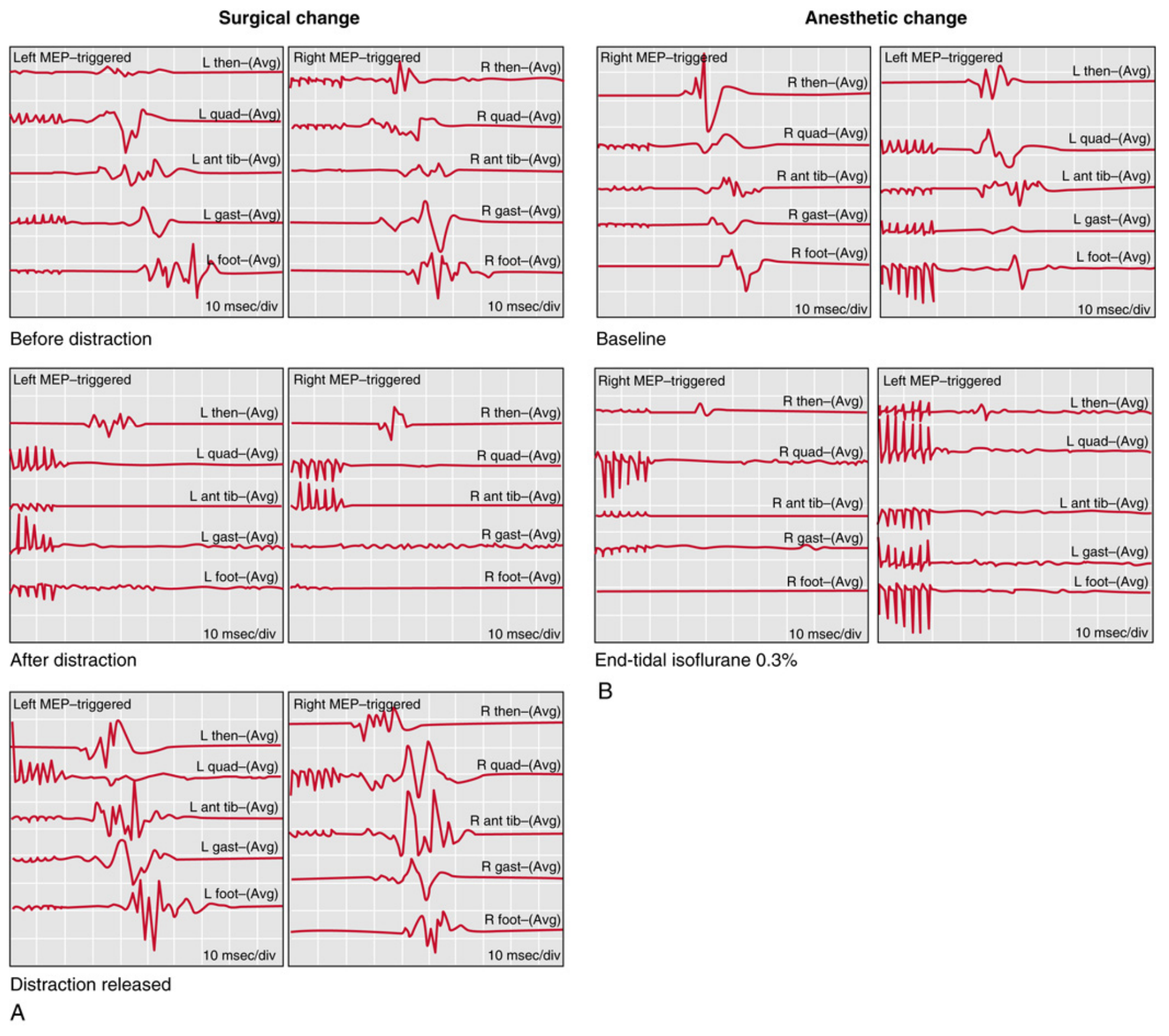
Alert Criteria (Significant Change Thresholds)
| Modality | Significant Change |
|---|---|
| tcMEP (muscle) | >50% amplitude decrease OR complete loss |
| D-wave (epidural) | >50% amplitude decrease |
| SSEP amplitude | >50% decrease |
| SSEP latency | >10% prolongation |
Distinguishing surgical from anesthetic changes:
- Surgical change: affects lower extremity signals only (unilateral or bilateral) while upper extremity signals are preserved
- Anesthetic change: affects ALL signals including upper extremity controls simultaneously (see figure above)
Response to Intraoperative MEP Alert
When MEP or SSEP changes occur beyond alert thresholds, the following systematic protocol is followed:
Step 1 - Pause Surgery
- Immediately alert surgeon and anesthesiologist
- Discontinue active surgical manipulation
Step 2 - Optimize Physiology
- Increase blood pressure to normal or 20% above normal (crucial - MEP highly sensitive to MAP)
- Maintain MAP ≥ 70 mmHg (especially important during DVR and correction maneuvers)
- Check oxygen saturation and ventilation (rule out hypoxia, hypercarbia)
- Reduce or discontinue volatile anesthetic agents
- Check arterial blood gases - rule out metabolic derangement
Step 3 - Surgical Intervention
- Release distraction on the cord
- Remove or reposition suspicious implants (rod, screw)
- Check screw positions (fluoroscopy)
Step 4 - Reassess
- Allow time for signal recovery
- If signal recovers - may resume surgery cautiously
- If signal does not return to normal - consider wake-up test
Step 5 - Wake-Up Test
- Perform definitive wake-up test if signal does not recover or if there is continued clinical concern
Triggered EMG - Pedicle Screw Monitoring
Principle: During pedicle screw placement, a ball-tip probe directly stimulates the screw with a small electrical current. If the screw has breached the bony pedicle near the spinal canal or nerve root, the current excites the adjacent nerve root at a lower threshold.
Threshold criteria:
- >6 mA (Campbell's) / >8 mA (Miller's): screw properly placed within intact pedicle
- <6 mA (Campbell's): alert the surgeon to possible pedicle breach
- Pedicle screws in healthy bone typically require >8 mA to elicit muscle responses (Miller's)
Types of EMG in spine surgery:
- Triggered EMG (active): stimulate screw/pedicle hole; record muscle CMAP
- Free-running (passive) EMG: continuously records all muscle responses; "neurotonic discharges" from nerve irritation appear as:
- Brief "popcorn" discharges: benign contact with nerve
- Response trains: significant nerve irritation
- Neurotonic discharges: significant nerve irritation/damage
Anesthesia Considerations for MEP Monitoring
This is critical as incorrect anesthesia abolishes MEP signals:
| Agent | Effect on MEP | Recommendation |
|---|---|---|
| Propofol infusion (TIVA) | Minimal suppression | Optimal |
| Opioid infusion | Minimal | Optimal |
| Volatile agents (isoflurane, halothane, desflurane) | Significant suppression | Avoid or minimize (<0.5 MAC) |
| Nitrous oxide | Suppression | Use with caution |
| Neuromuscular blocking agents (NMBs) | Abolishes muscle MEP | Must be avoided/partial only |
| Benzodiazepines | Suppression | Avoid (also affects SSEP) |
| Droperidol | Suppression | Avoid |
| Ketamine | Variable; may be suitable | Acceptable alternative |
| Etomidate | Minimal suppression; enhances SSEP amplitude (see Fig 35.13) | Suitable |
| Dexmedetomidine | Does not significantly affect evoked potentials | Suitable adjunct |
Optimal regimen for combined MEP+SSEP monitoring:
- Total Intravenous Anesthesia (TIVA) with propofol + ultrashort-acting opioid (remifentanil/fentanyl) infusion
- With EEG or BIS monitoring to minimize risk of intraoperative awareness
- No neuromuscular blockade (except transient for intubation)
- Low-dose or no volatile agents
Indications for Intraoperative MEP Monitoring in Spine Surgery
- Scoliosis correction (AIS, neuromuscular, congenital) - primary indication; correction/distraction forces endanger cord
- Cervical spine surgery (decompression, fusion, corpectomy)
- Thoracic spine surgery (discectomy, tumour, deformity)
- Spinal cord tumours (intramedullary, intradural)
- Spinal osteotomies (PSO, VCR, Smith-Petersen)
- Complex revision spinal surgery
- Thoracoabdominal aortic aneurysm repair (threat to artery of Adamkiewicz)
- Tethered spinal cord release
- Pedicle screw insertion in deformed/dysplastic anatomy
Contraindications and Precautions
| Contraindication | Reason |
|---|---|
| Cranial metallic implants (cochlear, DBS, aneurysm clips) | Risk of current diversion |
| Active scalp infection | Electrode placement risk |
| Skull defects | Cannot perform transcranial stimulation |
| History of epilepsy (relative) | Risk of seizure from stimulation |
| Cardiac pacemaker (relative) | Electrical interference |
| Children <4 years | Incomplete myelination of corticospinal pathways; D-waves unreliable |
| Fractured teeth/temporomandibular injury | Bite injuries from jaw clenching during stimulation |
Special precaution: Bite blocks must be placed to prevent tongue biting during high-voltage transcranial stimulation.
Specific Situations in Orthopaedic Spine Surgery
Scoliosis Surgery
- Standard of care (100% sensitivity, 87% specificity per Campbell's)
- Establish baseline MEP before any corrective maneuver
- Mandatory before rod derotation and direct vertebral rotation (DVR) maneuvers
- MAP ≥ 70 mmHg required during correction
- In neuromuscular scoliosis: wake-up test often not feasible; MEP/SSEP invaluable; achievable in 80% of cases including cerebral palsy patients (Campbell's)
- Congenital scoliosis: highest risk procedure for paraplegia after instrumentation - MEP monitoring most critical here
Cervical Surgery
- Ulnar nerve preferred over median for better lower cervical cord coverage
- MEP monitors C5-T1 cord and tracks impending myelopathy
Scoliosis Case Example (PMC review):
17-year-old girl with NF-1 scoliosis: During rod application with derotation/cantilever maneuver, MEP amplitude in both lower extremities decreased >50% vs baseline while SSEP remained unchanged - classic isolated anterior cord involvement. After rod and screw removal, MEP amplitude recovered. This illustrates the superiority of MEP over SSEP in detecting anterior cord ischemia.
Complications of MEP Monitoring
- Bite injuries (tongue, lip) - prevented by bite block
- Scalp burns at electrode sites (rare)
- Cardiac arrhythmias - rare; use low current protocols
- Seizures - rare with modern short-train stimulation protocols
- Patient movement during stimulation - may cause surgical mishap; careful coordination
Summary Comparison: Monitoring Modalities
| Feature | SSEP | tcMEP | Triggered EMG | Wake-Up Test |
|---|---|---|---|---|
| Pathway | Dorsal columns | Corticospinal tract | Nerve root | Global motor |
| Blood supply | Posterior spinal A | Anterior spinal A | Radicular | Both |
| Real-time | Near (every few min) | Yes | Yes | No (one point) |
| Anesthesia effect | Moderate | High | Low | Needs light anesthesia |
| NMB impact | Minimal | Abolishes | Abolishes | Compatible |
| Alert criterion | >50% amp / >10% lat | >50% amp or loss | <6 mA threshold | No movement |
| False negative rate | Higher | Lower | Low | Very low |
| Application | General cord | Anterior cord | Pedicle screw, root | Definitive check |
Key Points for Exam
- MEP monitors the anterior corticospinal tracts (anterior spinal artery territory) - pathway missed by SSEP alone
- Transcranial electrical stimulation → descends corticospinal tract → recorded as CMAP in muscles at 25-45 ms
- Alert criterion: >50% amplitude decrease in MEP
- MEP changes occur faster than SSEP after neurologic injury
- MEP is more sensitive to hypotension than SSEP - MAP must be maintained ≥ 70 mmHg
- TIVA (propofol + opioid) is optimal; volatile agents and NMB must be avoided
- Distinguishing surgical vs anesthetic change: anesthetic affects both upper and lower extremity channels
- Triggered EMG threshold: <6 mA = pedicle breach likely (Campbell's); >8 mA = safe placement (Miller's)
- Combined SSEP + MEP: 100% sensitivity, 87% specificity for spinal cord injury (Campbell's)
- Wake-up test: first described 1973 (Stagnara); still used when MEP/SSEP equivocal or unavailable
Conclusion
Motor evoked potentials have revolutionized the safety of spine surgery by providing continuous, real-time monitoring of the corticospinal tracts - the pathway most vulnerable to anterior spinal cord ischemia and most likely to be missed by SSEP alone. Combined multimodal monitoring (MEP + SSEP + triggered EMG) represents the current standard of care for all complex spinal procedures, with Level I evidence supporting its role in reducing neurological deficits. Proper understanding of the technique, alert criteria, anesthetic implications, and systematic response protocol is essential knowledge for every spine surgeon.
Sources: Campbell's Operative Orthopaedics 15th Ed 2026 (Ch. 40, Spinal Cord Monitoring); Barash, Cullen & Stoelting's Clinical Anesthesia 9th Ed; Miller's Anesthesia 10th Ed (Ch. 35); Bradley & Daroff's Neurology in Clinical Practice (Ch. 39); PMC IOM review - PMC4568525; AANS/CNS Position Statement on Intraoperative Electrophysiological Monitoring 2018
This is a shared conversation. Sign in to Orris to start your own chat.