
How to do contrast-enhanced computed tomography of paranasal sinus?
contrast enhanced CT paranasal sinuses technique protocol radiology
https://radiologykey.com/normal-anatomy-and-anatomic-variant…
https://pmc.ncbi.nlm.nih.gov/articles/PMC9895497
Contrast-Enhanced CT (CECT) of the Paranasal Sinuses
Overview
Indications for Contrast Enhancement
- Unilateral pathology - raises suspicion for neoplasm rather than bilateral inflammatory disease
- Suspected neoplasm - to assess tumor extent, vascular involvement, and enhancement characteristics
- Aggressive or invasive infections - especially invasive fungal sinusitis with orbital or intracranial spread
- Vascular pathology - vascular tumors (e.g., juvenile nasopharyngeal angiofibroma), carotid involvement
- Intracranial extension - epidural abscess, meningitis, cavernous sinus thrombosis as complications of sinusitis
- Intraorbital extension - orbital cellulitis, subperiosteal abscess
- Severe nasal polyposis - contrast demonstrates the characteristic "cascading" enhancement of polyps and helps characterize associated mucoceles
- Fungal sinusitis - to identify soft tissue and bony changes and extrasinus spread
Patient Preparation
- IV access: Insert a peripheral IV cannula (18-20G) in the antecubital fossa or dorsum of hand
- Check renal function: serum creatinine/eGFR before iodinated contrast, especially if there is renal disease, diabetes, or dehydration
- Screen for contrast allergy history: prior reactions, iodine allergy, asthma
- Premedication: if prior mild/moderate reaction, consider corticosteroid + antihistamine premedication
- Hydration: ensure adequate oral or IV hydration, especially in patients at risk for contrast-induced nephropathy
- Metformin: withhold 48 hours before and after contrast if significant renal impairment
- Informed consent and IV contrast injection instructions
Scanner Setup and Technical Protocol
| Parameter | Specification |
|---|---|
| Patient position | Supine, head first |
| Gantry tilt | None (0°) - essential for image-guided navigation |
| Collimation | 64 × 0.625 mm (or equivalent on ≥16-row MDCT) |
| Slice thickness | ≤1 mm (0.67 mm reconstruction) |
| Increment | 0.33 mm |
| Reconstruction capability | Down to 0.20 mm |
| FOV | 180 mm (sinus-limited), or extended to include both ears + frontal sinuses for navigation protocols |
| Pitch | ~0.641 |
| kVp | 120 kV (100 kV is acceptable - good CNR with less dose) |
| mAs | 200 mA/slice (low-dose protocols 50-100 mAs are viable for non-neoplastic indications) |
| Rotation time | 0.5 s |
| Reconstruction filter/kernel | Bone algorithm (Y-sharp or equivalent) for bony detail; soft tissue algorithm when evaluating soft tissue extension |
| Image matrix | 512 × 512 |
Contrast Agent and Injection Protocol
- Agent: Non-ionic iodinated contrast (e.g., iohexol, iopamidol, iodixanol)
- Dose: ~1.5-2 mL/kg body weight (typically 80-100 mL in adults)
- Concentration: 300-370 mgI/mL
- Injection rate: 2-3 mL/s via IV
- Scanning delay: 60-70 seconds (portal venous/soft tissue phase) for most indications; arterial phase (~25-30 s) if a vascular lesion is suspected
- For suspected tumor invasion: a delayed phase (3-5 minutes) may be added to assess contrast retention vs. washout
Scan Acquisition
- Survey/scout image (topogram): Lateral and AP scouts to confirm positioning and coverage (from top of frontal sinuses to hard palate)
- Pre-contrast scan: Recommended baseline, especially for tumors or vascular lesions, to identify intrinsic hyperdensity (calcification, hemorrhage)
- Post-contrast scan: Acquire in the axial plane, volume acquisition, no gantry tilt
- Coverage: From the floor of the frontal sinus superiorly to the hard palate/inferior maxillary alveolus inferiorly
Image Reconstruction and Viewing
-
Multiplanar reconstruction (MPR): The axial volume dataset is reconstructed in all three orthogonal planes:
- Coronal plane: Most useful for OMC anatomy, extent of mucosal disease, pre-FESS planning, and cribriform plate assessment
- Sagittal plane: Best for frontal sinus drainage pathway (frontal recess), anterior ethmoid air cells, lateral nasal wall
- Axial plane: Best for optic nerves, pterygopalatine fossa, fossa of Rosenmuller, posterior table of frontal sinus, orbital walls
-
Window settings:
- Bone window: WW 2000-4000 HU, WL 400-700 HU - for bony detail, sinus walls, OMC anatomy
- Soft tissue window: WW 350-400 HU, WL 40-60 HU - for mucosal enhancement, soft tissue lesions, intracranial/intraorbital extension
- Custom windows: Gradually lowering the window level (WL) makes air spaces more conspicuous; lung-window-like settings help delineate air cell boundaries. Do NOT try to evaluate soft tissue details from bone window images - this degrades image quality unacceptably.
Interpreting CECT Findings
| Finding | Significance |
|---|---|
| Enhancing soft tissue mass | Neoplasm (benign or malignant); distinguish from non-enhancing retained secretions |
| Rim enhancement of sinus contents | Mucosal thickening with thin luminal enhancement - characteristic of chronic sinusitis |
| No enhancement of sinus secretions | Confirms retained secretions/secretory contents (vs. tumor) |
| Avid/heterogeneous enhancement | Suggests vascular tumor (e.g., angiofibroma, hemangioma) |
| Intracranial enhancement | Meningeal enhancement = meningitis; ring-enhancing collection = abscess |
| Perineural spread | Enhancing nerve thickening along trigeminal branches (V2) in malignant tumors |
| Cavernous sinus enhancement | Cavernous sinus thrombosis complicating sphenoid sinusitis |
Post-Procedure Care
- Monitor patient for 15-30 minutes post-injection for delayed contrast reactions
- Encourage oral hydration after the procedure
- Document contrast dose, lot number, and any adverse reactions
- Resume metformin 48 hours post-procedure after confirming stable renal function
Key Points
- Routine pre-FESS CT is always non-contrast - contrast adds no benefit for anatomic mapping of the OMC
- CECT is reserved for unilateral, neoplastic, vascular, or complicated infectious pathology
- Isotropic sub-millimeter acquisition with MPR in all three planes is essential; any ≥16-row MDCT can achieve this
- Soft tissue windows on CECT are essential for assessing mucosal enhancement and extrasinus spread; bone windows alone are insufficient
- MRI with gadolinium is preferred over CECT for intracranial extension, perineural spread, and distinguishing tumor from obstructed secretions - CECT is a complementary modality
Please visualize what is the patient position, where we have to put center, and... What is the reconstruction slice thickness in every, uh, axial, coronal, and, uh, sagittal? Already.
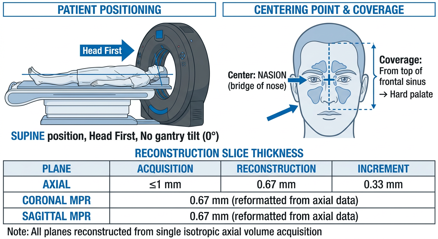
A clear medical radiology diagram showing CT scan setup for paranasal sinuses. Three sections in one image: 1. TOP SECTION - Patient positioning: A patient lying supine (face up) on a CT scanner table, head first into the gantry. The head is in neutral position (Reid's baseline or orbitomeatal line parallel to the table). Label: "SUPINE position, Head First, No gantry tilt (0°)". Show the CT gantry as a large ring around the patient's head. 2. MIDDLE SECTION - Centering point diagram: A front-facing diagram of a human face/head showing the isocenter/centering point marked with a crosshair (+) at the NASION (bridge of nose, between the eyes). Label arrows pointing to: "Center: NASION (bridge of nose)" and "Coverage: From top of frontal sinus → Hard palate". Show a vertical dashed line from forehead to upper lip indicating the scan range. 3. BOTTOM SECTION - A clean table/chart showing reconstruction slice thickness for each plane: Title: "Reconstruction Slice Thickness" Row 1: AXIAL | Acquisition: ≤1 mm | Reconstruction: 0.67 mm | Increment: 0.33 mm Row 2: CORONAL MPR | 0.67 mm (reformatted from axial data) Row 3: SAGITTAL MPR | 0.67 mm (reformatted from axial data) Note at bottom: "All planes reconstructed from single isotropic axial volume acquisition" Use clean white background, blue and dark grey color scheme, neat medical illustration style with bold labels.
Patient Position
- Supine, head first into the gantry
- Head in neutral/straight position - no flexion, no extension
- No gantry tilt (0°) - mandatory, especially for image-guided navigation systems
Centering Point
- Center at the nasion (bridge of the nose, between the two eyes)
- Coverage: From the top of the frontal sinuses superiorly → down to the hard palate inferiorly
Reconstruction Slice Thickness
| Plane | How Obtained | Slice Thickness | Increment |
|---|---|---|---|
| Axial | Primary acquisition | ≤ 1 mm (0.67 mm) | 0.33 mm |
| Coronal MPR | Reformatted from axial data | 0.67 mm | same dataset |
| Sagittal MPR | Reformatted from axial data | 0.67 mm | same dataset |
Anatomy of paranasal sinus in CT image.
paranasal sinus CT anatomy labeled images axial coronal sagittal radiology
Anatomy of Paranasal Sinuses on CT
1. Nasal Cavity - Coronal + Sagittal CT
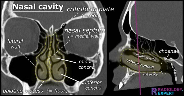
- Cribriform plate = roof of nasal cavity
- Nasal septum = medial wall
- Lateral wall = contains the turbinates
- Palatine process = floor
- Middle and inferior conchae (turbinates)
- Choanae - posterior openings into the nasopharynx
2. Coronal CT - All Three Planes (Textbook: Cummings Otolaryngology)
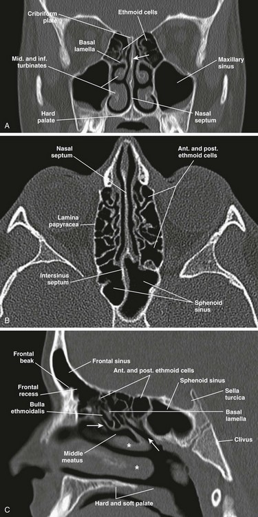
- Ethmoid cells (roof) - between orbits, honeycomb appearance
- Cribriform plate - at the top, separates ethmoid from anterior cranial fossa
- Basal lamella - divides anterior from posterior ethmoid
- Middle and inferior turbinates
- Maxillary sinuses - bilateral large air spaces below the orbits
- Nasal septum
- Hard palate (floor)
- Nasal septum - midline
- Anterior and posterior ethmoid cells
- Lamina papyracea - paper-thin medial orbital wall (important surgical landmark)
- Intersinus septum
- Sphenoid sinus - posterior midline structure
- Frontal sinus - anterior superior
- Frontal recess (frontal beak) - drainage pathway of frontal sinus
- Anterior and posterior ethmoid cells
- Bulla ethmoidalis - largest anterior ethmoid cell
- Sphenoid sinus - posterior
- Sella turcica - above sphenoid sinus
- Basal lamella
- Middle meatus (asterisks)
- Clivus
- Hard and soft palate
3. Sagittal + Axial Views (More Detail)
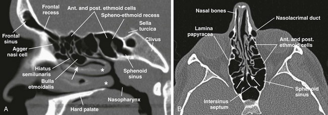
- Agger nasi cell - most anterior ethmoid cell, just anterior to the frontal recess
- Frontal recess - drainage pathway between frontal sinus and middle meatus
- Hiatus semilunaris - crescent-shaped gap between uncinate process and bulla
- Bulla ethmoidalis
- Sphenoethmoidal recess - drains sphenoid sinus into superior meatus
- Sphenoid sinus, Nasopharynx
- Nasal bones
- Lamina papyracea - medial orbital wall
- Nasolacrimal duct - anterolateral
- Anterior and posterior ethmoid cells
- Intersinus septum
- Sphenoid sinus with its intersinus septum
4. Ostiomeatal Complex (OMC) - Coronal CT
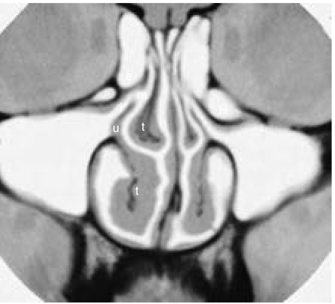
| Label | Structure | Role |
|---|---|---|
| e | Ethmoid bulla | Lateral wall of infundibulum |
| m | Middle meatus | Common drainage pathway |
| u | Uncinate process | Medial wall of infundibulum |
| t | Turbinates (middle + inferior) | Nasal airflow regulation |
| H | Haller cell (variant) | Can narrow the infundibulum |
| i | Infundibulum | Drainage channel of maxillary sinus |
5. Axial CT - Nasal Cavity Detail
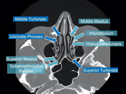
- Middle turbinate and middle meatus
- Uncinate process - thin curved bony plate, key FESS landmark
- Infundibulum - the drainage channel lateral to uncinate
- Hiatus semilunaris - the crescent gap opening
- Superior turbinate and superior meatus
- Sphenoethmoidal recess - drains the sphenoid sinus
Summary: What to Identify on Each Plane
| Plane | Best for Visualizing |
|---|---|
| Coronal | OMC, maxillary sinus drainage, ethmoid cells, cribriform plate, orbital floor |
| Axial | Sphenoid sinus, posterior ethmoids, lamina papyracea, nasolacrimal duct, skull base |
| Sagittal | Frontal recess, frontal sinus drainage, basal lamella, sphenoethmoidal recess |