
Osteology of upper limbs in details
upper limb bones anatomy diagram skeleton
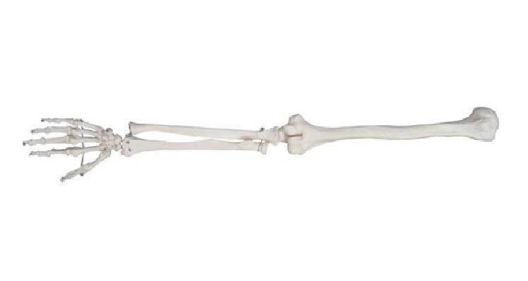
This anatomical diagram displays the skeletal structure of the human upper limb, positioned horizontally from proximal to distal (right to left). The image captures the three main segments: the upper arm, the forearm, and the hand. Key structures include the humerus (upper arm bone), which articulates proximally with the shoulder and distally at the elbow joint with the radius and ulna. The forearm is shown with the radius and ulna running parallel, demonstrating their relationship in a supinated or neutral position. The distal forearm articulates with the carpus (wrist), composed of eight small carpal bones. Moving further distally, the image illustrates the metacarpals forming the palm and the phalanges (proximal, middle, and distal) forming the digits. The thumb is clearly visible with its two phalanges, while the other four fingers each contain three. This visualization serves as a foundational educational tool for identifying skeletal landmarks, joint articulations, and the proportional relationships within the human appendicular skeleton.
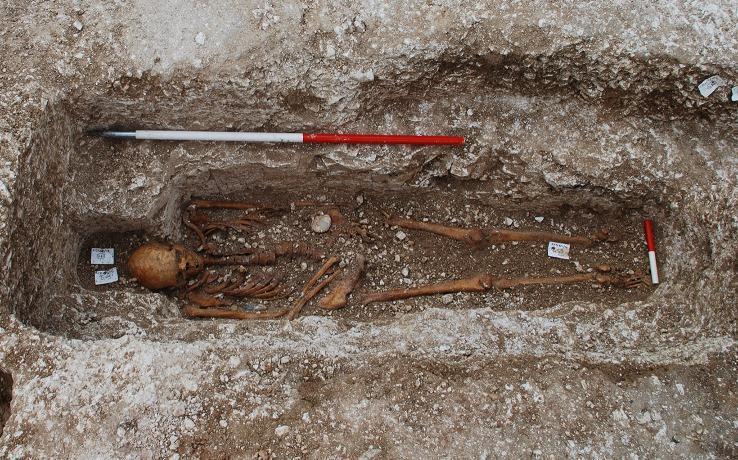
This clinical photograph shows a well-preserved human skeleton (designated Sk27) in situ within a medieval chalk-cut anthropomorphic grave. The remains are positioned in a supine, extended orientation. Visual analysis of the skeletal anatomy reveals the skull, rib cage, and long bones are largely intact but demonstrate post-mortem disarticulation. The left upper limb is positioned straight at the side, while the right upper limb is flexed at the elbow with the hand resting near the pelvic region. Located on the left side of the pelvis is a distinct scallop shell (Pecten maximus), used as a cultural symbol. Educational relevance includes paleopathology and forensic archaeology; though the skeleton appears grossly unremarkable, molecular analysis and subtle distal pedal phalangeal resorption (achro-osteolysis) in this specific individual are associated with early-stage leprosy (Mycobacterium leprae). An archaeological scale bar is visible alongside the burial to provide dimensions. The context demonstrates the intersection of bioarchaeology and historical clinical pathology.
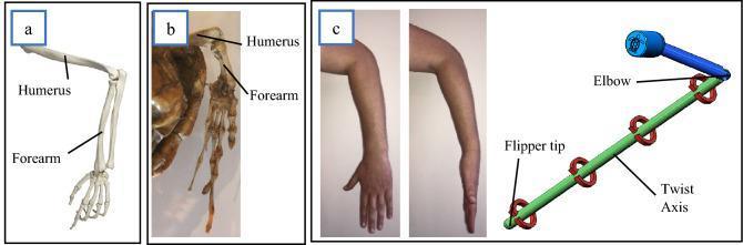
This educational graphic provides a comparative anatomical and biomechanical analysis of the upper limb, focusing on skeletal homology and rotational mechanics. Panel (a) features an anatomical diagram of the human arm skeleton, identifying the humerus and the forearm (radius and ulna). Panel (b) shows a clinical photograph of a Hawksbill sea turtle flipper skeleton, illustrating the homologous humerus and forearm structures adapted for aquatic locomotion. Panel (c) contains clinical photographs of a human arm demonstrating forearm pronation and supination, alongside a biomechanical CAD model. The human photographs show the rotational transition from a palm-forward to a palm-down position, occurring independently of humerus rotation. The adjacent CAD model illustrates this 'twist axis' between the elbow and the flipper tip, using red circular arrows to represent rotational degrees of freedom. This comparison teaches concepts of comparative anatomy, musculoskeletal kinematics, and the mechanical modeling of biological joints, specifically how the human forearm's ability to twist serves as a biological analog for sea turtle flipper hydrodynamics.
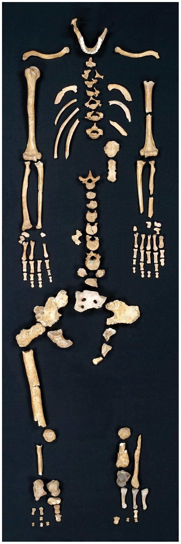
This clinical photograph displays the Regourdou 1 skeleton, an archaeologically significant partial Neanderthal skeleton laid out in an anatomical approximation on a dark background. The axial skeleton is represented by a mandible with a complete set of erupted teeth, a segmented vertebral column showing various cervical, thoracic, and lumbar vertebrae, and a partial superior sacrum. The thoracic cage includes bilateral clavicles and several fragmented ribs. The appendicular skeleton features both upper and lower limbs. The upper limbs include the humeri, radii, ulnae, and relatively complete disarticulated hands. The lower skeleton comprises fragmented bilateral ilia (pelvic girdle), a prominent right femur shaft, and scattered pedal elements. Many bones exhibit taphonomic changes, including significant fragmentation and disarticulation. Preservation is asymmetrical, with the right upper limb showing greater completeness than the left. This specimen is used in paleoanthropology to study Neanderthal anatomy, biomechanical stress (through cortical bone analysis), and behavioral traits such as handedness based on dental wear patterns.
scapula anatomy diagram labeled
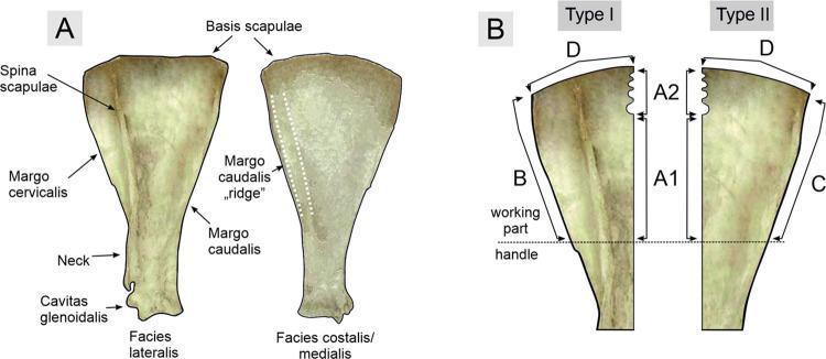
This educational anatomical diagram and specimen comparison illustrate the osteological terminology of the scapula and its modification into tools. Panel A displays two views of a scapula, labeled 'Facies lateralis' and 'Facies costalis/medialis'. Key anatomical landmarks include the Spina scapulae, Basis scapulae, Margo cervicalis, Margo caudalis (with a highlighted 'ridge'), Neck, and Cavitas glenoidalis. Panel B demonstrates the classification of archaeological 'Bruszczewo-type' osseous tools derived from these bones, categorized into Type I and Type II based on their morphological origins. The diagram uses a numbering scheme for working edges: 'A1' (smooth longitudinal edge), 'A2' (notched edge), 'B' (approximating the Margo cervicalis), 'C' (approximating the Margo caudalis), and 'D' (distal curved edge). A horizontal dashed line differentiates the 'working part' from the 'handle' section of the modified specimens. This visual comparison provides a technical bridge between human/animal anatomy and bioarchaeological tool analysis.
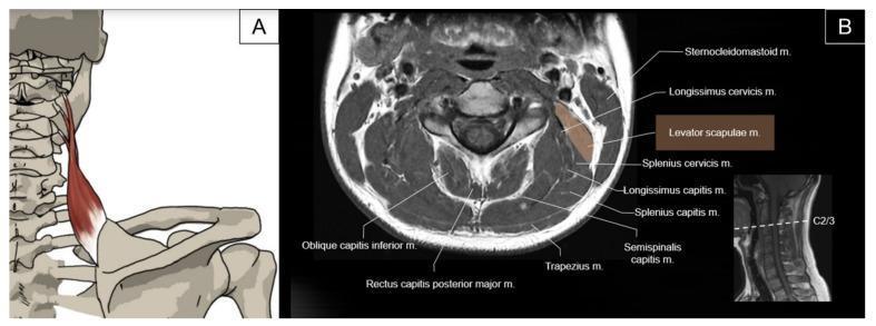
This composite educational graphic focuses on the anatomy of the levator scapulae muscle. Panel A is an anatomical diagram showing the posterior view of the cervical spine and scapula. The levator scapulae is highlighted in red, originating from the transverse processes of the C1–C4 vertebrae and inserting on the superior angle and medial border of the scapula. Panel B features an axial T1-weighted magnetic resonance image (MRI) at the C2/3 level, as indicated by a sagittal localizer image. The levator scapulae muscle is shaded in tan on the right side of the image, demonstrating its cross-sectional relationship with adjacent musculature. It is positioned deep to the sternocleidomastoid and trapezius muscles, and lateral to the longissimus cervicis and splenius cervicis. Other labeled posterior neck muscles include the semispinalis capitis, splenius capitis, oblique capitis inferior, and rectus capitis posterior major. This content is intended for medical education regarding neck and shoulder girdle musculoskeletal anatomy and radiological identification.
humerus bone anatomy anterior posterior view labeled
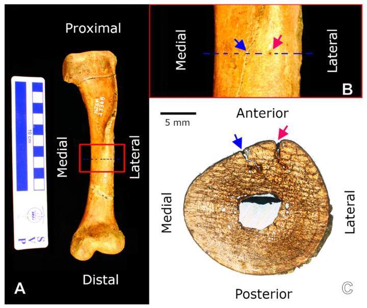
Educational panel illustrating the gross and microscopic anatomy of a left humerus. (A) Clinical photograph of the anterior view of the humerus, labeled with proximal, distal, medial, and lateral orientations. A 10 cm scale bar is included. A red box identifies the mid-diaphyseal region. (B) Close-up view of the mid-diaphyseal shaft showing a longitudinal crack (blue arrow) and a nutrient foramen (red arrow). A dotted blue line indicates the plane for histological sectioning. (C) Transverse thin section (histology) of the mid-diaphysis, oriented with anterior, posterior, medial, and lateral markers. A 5 mm scale bar is provided. The section reveals a thick cortical bone matrix surrounding a central, open medullary cavity. The microscopic view demonstrates primary and secondary bone tissue patterns, with the crack (blue arrow) and nutrient foramen (red arrow) visible on the anterior cortical margin. This material provides a comparison between external morphological landmarks and internal microstructural features, relevant for osteological and histological study.
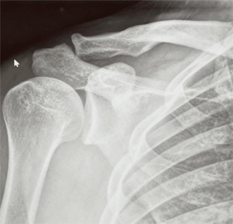
Anterior-posterior (AP) diagnostic X-ray of the right shoulder girdle, demonstrating the musculoskeletal anatomy of the glenohumeral and acromioclavicular joints. The image provides a clear view of the proximal humerus, including the humeral head and greater tuberosity, the glenoid fossa of the scapula, the acromion, the coracoid process, and the lateral aspect of the clavicle. The cortical margins are sharp and continuous with no evidence of acute fracture, cortical disruption, or periosteal reaction. The glenohumeral joint space is preserved, with the humeral head properly centered within the glenoid, ruling out dislocation. The acromioclavicular (AC) joint also appears within normal limits without widening or elevation. The trabecular bone density and distribution appear unremarkable for an adult patient. In a clinical context involving soft tissue injuries like pectoralis major ruptures, this radiographic study serves as a baseline to exclude associated bony pathology, such as avulsion fractures or shoulder instability. This imaging is characteristic for orthopedic evaluation in emergency and sports medicine settings.
carpal bones wrist anatomy diagram
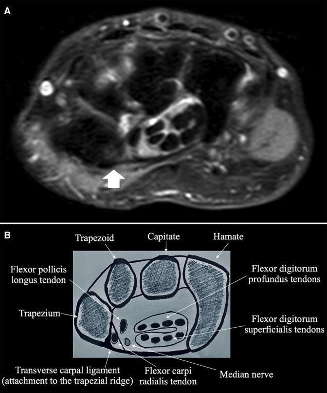
This composite educational graphic focuses on the wrist's carpal tunnel anatomy, consisting of an axial MRI image (A) and a corresponding labeled anatomical diagram (B). Image A is a proton density fat-suppressed (PD FS) MRI of a right hand, demonstrating the normal, low-signal intensity of an intact transverse carpal ligament (TCL). A white arrow indicates the ligament's lateral attachment point at the trapezial ridge. Image B provides a schematic cross-section at the same anatomical level, labeling key structures: the carpal bones (trapezium, trapezoid, capitate, and hamate), the median nerve, and various tendons including the flexor pollicis longus, flexor carpi radialis, flexor digitorum profundus, and flexor digitorum superficialis. The diagram clearly illustrates the TCL forming the roof of the carpal tunnel, specifically highlighting its lateral insertion on the trapezium. This comparison serves as a clinical reference for identifying normal TCL morphology and signal continuity, which is essential for diagnosing ligamentous tears or carpal tunnel pathology.
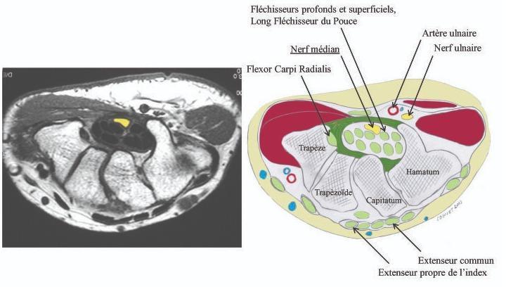
This medical visual consists of a side-by-side comparison between an axial magnetic resonance imaging (MRI) scan of the human wrist and a corresponding anatomical cross-section diagram. The image illustrates the anatomy of the carpal tunnel and surrounding structures. Key elements identified include the carpal bones (trapezium, trapezoid, capitate, and hamate) forming the floor and walls of the tunnel. Centrally located within the carpal tunnel, the median nerve is highlighted in yellow, positioned superficially to the deep and superficial flexor tendons and the long flexor tendon of the thumb. The flexor carpi radialis is shown in its distinct compartment. Outside the flexor retinaculum on the ulnar side, the ulnar artery and ulnar nerve are clearly demarcated. Posteriorly, the extensor tendons, including the extensor digitorum and extensor indicis, are visible. This educational material is designed to demonstrate the spatial relationship of the median nerve within the confined carpal space, which is clinically relevant for diagnosing and treating carpal tunnel syndrome.
radius ulna forearm bones anatomy labeled
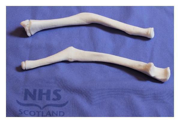
This clinical photograph displays two physical, 3D-printed anatomical models of human forearm bones, identified as the radius and ulna, placed on a blue surgical drape. These models represent patient-specific anatomy derived from CT scan data for preoperative planning. The models demonstrate clinical pathology, specifically a significant mid-shaft malunion of the forearm bones. This is characterized by a prominent bony apex and dorsal angulation (approximately 40 degrees) along the diaphysis, which contributes to restricted pronation and supination. Visible landmarks include the proximal radial head and the distal ulnar styloid process and head. The educational focus is on the application of 3D rapid prototyping in orthopedic surgery to visualize complex bony deformities, such as malunited fractures, which aid in the preparation for corrective osteotomies. The models serve as tangible specimens for assessing anatomical distortion and planning precise surgical correction.
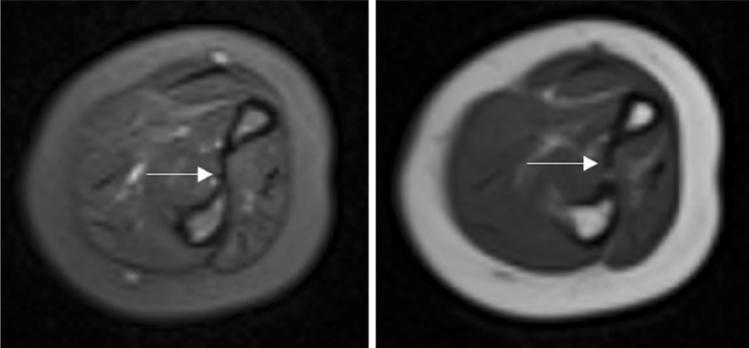
This diagnostic image displays side-by-side axial MRI scans of the human forearm, featuring a T2-weighted sequence (left) and a T1-weighted sequence (right). The cross-sectional anatomy clearly depicts the radius and ulna bones, surrounded by muscle compartments and a thick layer of subcutaneous fat. In the T1-weighted image, the bone marrow and subcutaneous fat exhibit a high (bright) signal, while the muscles appear with intermediate signal intensity. In the T2-weighted image, the fat remains bright, but fluid and certain soft tissue details show increased contrast. A white arrow in both images points specifically to the interosseous membrane, which appears as a thin, continuous, low-signal (dark) band spanning the space between the radius and ulna. The membrane shows no signs of tearing, thickening, or edema, indicating no acute injury. This comparison is used in clinical education to demonstrate normal musculoskeletal ligamentous structures and the signal characteristics of different forearm tissues in the context of orthopedic evaluation for conditions like Monteggia fractures.
carpal metacarpal phalanges hand bones labeled anatomy
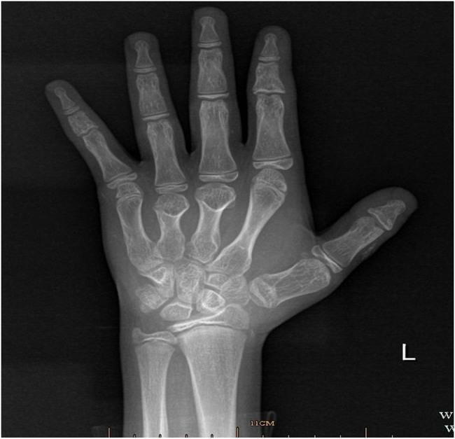
This diagnostic image is an anteroposterior (AP) X-ray of the left hand of a pediatric patient, demonstrating the skeletal anatomy including carpal bones, metacarpals, and phalanges. The primary pathological finding is brachydactyly, characterized by the disproportionate shortening of the third (middle) and fourth (ring) digits. This shortening is most prominent in the metacarpals and phalanges of these digits relative to the second and fifth fingers. The carpal bones are clustered at the wrist, and open growth plates (epiphyseal plates) are visible at the distal radius, ulna, and across the metacarpal and phalangeal joints, consistent with a juvenile skeleton. Such skeletal manifestations, particularly short fourth metacarpals, are classic clinical signs of Albright Hereditary Osteodystrophy (AHO), often seen in Pseudohypoparathyroidism (PHP). The image serves as an educational example of how hand radiography can assist in the diagnostic workup of metabolic and genetic endocrine disorders.
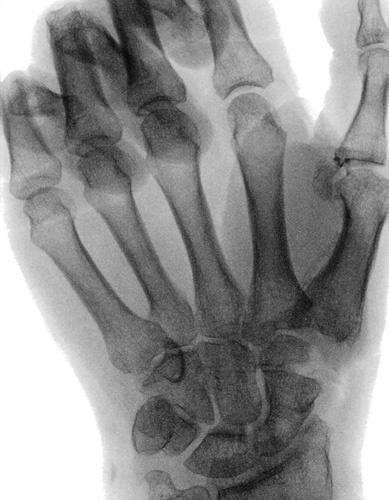
This intraoperative fluoroscopic image (X-ray) depicts the skeletal anatomy of the human hand and wrist, with a primary focus on the carpus and metacarpal region during a surgical suspension procedure. The image shows the five metacarpals, carpal bones including the scaphoid and capitate, and the proximal phalanges. A notable feature is the absence or surgical alteration of the trapezium, characteristic of a trapeziectomy for the treatment of basal joint (thumb CMC) arthritis. The first metacarpal is positioned in relative opposition to the second metacarpal. Bone density and alignment of the remaining carpal and metacarpal structures appear normal within the surgical context. This diagnostic and interventional image serves as a clinical reference for orthopedic hand surgery, illustrating the anatomical space created and the alignment maintained between the first and second metacarpals following trapezial resection and suspensionplasty.
scapula costal posterior surface anatomy glenoid coracoid
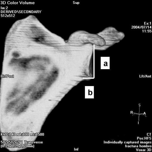
This diagnostic image features a 3D color volume reconstruction from a Computed Tomography (CT) scan of a human scapula, presented in an anterior-lateral orientation. Labeled anatomical landmarks include the superior (Sup) and inferior (Inf) borders, with directional markers indicating right/posterior (Rt/Post) and left/anterior (Lft/Ant) aspects. The image demonstrates specific morphometric measurements used to calculate the inferior glenoid neck index. Measurement 'a' is a vertical line representing the articular glenoid surface measure, extending from the superior margin of the glenoid fossa. Measurement 'b' is a horizontal line measuring the distance from the articular glenoid surface to the anterior column of the scapula. These perpendicular lines are used in orthopedic radiology to categorize scapular anatomy into 'short-neck' or 'long-neck' clusters, which has clinical significance for shoulder arthroplasty and fracture management. The coracoid process is clearly visible extending anteriorly, and the glenoid fossa is oriented towards the viewer.
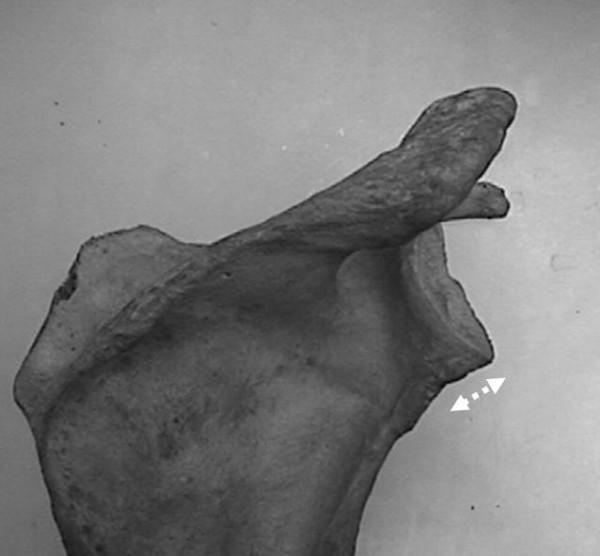
This clinical photograph displays a dry bone cadaveric specimen of a human scapula, viewed from a posterior perspective to highlight the morphology of the glenoid neck. Key anatomical landmarks include the glenoid fossa positioned laterally, the coracoid process extending superiorly and anteriorly, and the acromion process. The focal point is the 'long-neck' variation of the glenoid, where the distance between the glenoid articular surface and the medial scapular body is elongated. A white, double-headed dashed arrow is placed at the inferior aspect of the glenoid neck to visually emphasize this longitudinal dimension. The image serves as an educational reference for orthopedic anatomy and morphometric studies, demonstrating variations in scapular architecture that influence biomechanics and the placement of glenoid components in total shoulder arthroplasty.
Osteology of the Upper Limb - Detailed Notes
- Shoulder Girdle - Clavicle + Scapula
- Arm - Humerus
- Forearm - Radius + Ulna
- Hand - Carpals, Metacarpals, Phalanges
1. SHOULDER GIRDLE
A. CLAVICLE
- Medial two-thirds: convex anteriorly (rounded)
- Lateral one-third: concave anteriorly (flat)
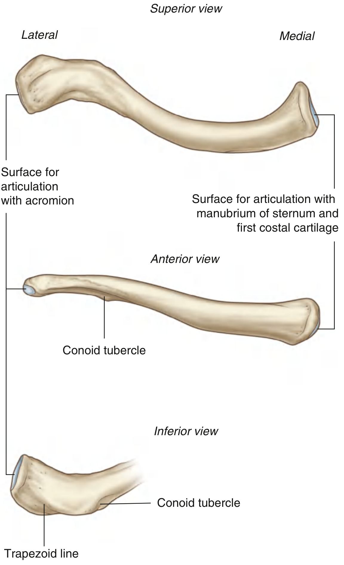
Ends
| Feature | Medial (Sternal) End | Lateral (Acromial) End |
|---|---|---|
| Shape | Quadrangular, robust | Flat, oval |
| Articulation | Manubrium sterni + 1st costal cartilage | Acromion of scapula (small oval facet) |
| Joint type | Sternoclavicular joint | Acromioclavicular joint |
Surfaces and Borders
- Superior surface: Relatively smooth; gives attachment to sternocleidomastoid (medially) and deltoid/trapezius (laterally)
- Inferior surface: Roughened; key landmarks include:
- Costal tuberosity (medially) - for costoclavicular ligament
- Conoid tubercle - for conoid part of coracoclavicular ligament
- Trapezoid line - lateral roughening for trapezoid part of coracoclavicular ligament
- Subclavian groove (middle third) - for subclavius muscle
Clinical Points
- Most commonly fractured bone in the body (indirect fall on outstretched hand)
- The junction between medial and lateral curves is the weakest point - most fractures occur here
- Only bone to ossify by intramembranous ossification in the upper limb; first bone to ossify (5th-6th week in utero) but last to complete ossification (25 years)
- Acts as a strut, keeping the shoulder and arm away from the thorax
B. SCAPULA
- 3 Angles: Superior, Inferior, Lateral
- 3 Borders: Superior, Medial (vertebral), Lateral (axillary)
- 2 Surfaces: Costal (anterior/subscapular) and Posterior (dorsal)
- 3 Processes: Spine, Acromion, Coracoid Process
Surfaces
- Large, concave surface facing anteriorly
- Contains the subscapular fossa - where the subscapularis muscle attaches
- Divided by the spine of scapula into:
- Supraspinous fossa (above spine) - for supraspinatus
- Infraspinous fossa (below spine) - for infraspinatus
Borders
- Superior border: Shortest border; contains the suprascapular notch (converted into foramen by the superior transverse scapular ligament; suprascapular nerve passes through, vessels over the ligament)
- Medial (vertebral) border: Parallel to the vertebral column; serratus anterior attaches along its costal surface
- Lateral (axillary) border: Thickest; runs from glenoid cavity to inferior angle
Angles
- Lateral angle: Bears the glenoid cavity - shallow, comma-shaped articular surface for the head of humerus. Separated from the rest of the bone by the surgical neck of scapula
- Supraglenoid tubercle (above): attachment for long head of biceps brachii
- Infraglenoid tubercle (below): attachment for long head of triceps brachii
- Superior angle: At the junction of superior and medial borders
- Inferior angle: At junction of medial and lateral borders; lies opposite T7-T8; used as a landmark; covered by latissimus dorsi
Processes
- Horizontal bony projection on posterior surface
- Continues laterally as the acromion
- Root of the spine is at the level of T3
- Flat, triangular projection overhanging the shoulder joint
- Articulates with the clavicle (acromioclavicular joint)
- Has attachment for deltoid (anterior surface) and trapezius (posterior surface)
- The angle between the acromion and spine palpable as a bony landmark
- Finger-like process projecting anterosuperiorly from the superior border of the neck of scapula
- Attachments: pectoralis minor (tip), short head of biceps + coracobrachialis (tip), coracohumeral ligament, coracoclavicular ligament (trapezoid + conoid)
2. ARM - HUMERUS
Proximal End
- Head: Hemispherical, faces medially, posteriorly, and upward; articulates with the glenoid cavity. Covered entirely by articular cartilage
- Anatomical neck: The slight constriction immediately surrounding the head (separates articular margin from tuberosities); intracapsular
- Greater tuberosity: Large projection on the lateral side; has 3 facets for:
- Superior: supraspinatus
- Middle: infraspinatus
- Inferior: teres minor
- Lesser tuberosity: Smaller, on the anterior aspect; for subscapularis muscle
- Intertubercular (bicipital) groove/sulcus: Between the two tuberosities; transmits the tendon of the long head of biceps brachii; floor for latissimus dorsi, medial lip for teres major, lateral lip for pectoralis major
- Surgical neck: Constriction immediately below both tuberosities; most common site of humerus fractures; the axillary nerve and posterior circumflex humeral artery are closely related here
Shaft
- Anterolateral: deltoid tuberosity (V-shaped roughening at the junction of upper and middle thirds) for deltoid; above the deltoid tuberosity, covered by deltoid
- Anteromedial: upper part smooth (below bicipital groove); lower part for brachialis and coracobrachialis
- Posterior: broad, flat; marked by the spiral (radial) groove (musculospiral groove) - carries the radial nerve and profunda brachii artery obliquely from medial to lateral
- Deltoid tuberosity: Midshaft laterally; for deltoid insertion
- Spiral/radial groove: Runs posteriorly from medial to lateral; radial nerve injury in mid-shaft humeral fractures ("Saturday night palsy")
- Nutrient foramen: Usually on the anteromedial surface, directed upward
Distal End
- Capitulum (lateral): Round, hemisphere for articulation with the head of radius
- Trochlea (medial): Pulley-shaped groove for articulation with the trochlear notch of ulna
- Medial epicondyle: Large, prominent; ulnar nerve lies in the groove on its posterior surface; attachment for common flexor origin (pronator teres, flexor carpi radialis, palmaris longus, flexor carpi ulnaris, flexor digitorum superficialis)
- Lateral epicondyle: Less prominent; attachment for common extensor origin (extensor carpi radialis brevis, extensor digitorum, extensor digiti minimi, extensor carpi ulnaris, anconeus)
- Coronoid fossa (anterior): Receives the coronoid process of ulna in full flexion
- Radial fossa (anterior, lateral to coronoid fossa): Receives the head of radius in full flexion
- Olecranon fossa (posterior): Receives the olecranon of ulna in full extension - deepest fossa
- Lateral supracondylar ridge: from lateral epicondyle upward; for brachioradialis and extensor carpi radialis longus
- Medial supracondylar ridge: occasionally has a supracondylar process (10 cm above medial epicondyle; Struthers ligament may trap the median nerve)
3. FOREARM
A. RADIUS
- Head: Cylindrical disc; superior surface (articular fovea) for capitulum; circumference (articular circumference) for radial notch of ulna (proximal radioulnar joint)
- Neck: Constriction below the head
- Radial tuberosity (bicipital tuberosity): Just below the neck, on the medial aspect; for insertion of biceps brachii
- Slightly curved (convex laterally)
- Three surfaces: anterior, posterior, medial
- Three borders: anterior, posterior, interosseous (medial/sharp) - for interosseous membrane
- Anterior surface: Has the pronator teres impression (upper third) and nutrient foramen
- Posterior surface: Has extensor pollicis longus obliquely across it
- Carpal articular surface: Has scaphoid fossa (lateral) and lunate fossa (medial), separated by a ridge; bears articular cartilage
- Sigmoid notch (ulnar notch): Medial concavity for the head of ulna (distal radioulnar joint)
- Styloid process of radius: Projects distally from the lateral aspect; tip is 1-1.5 cm more distal than the ulnar styloid (important clinically); attachment for brachioradialis and extrinsic wrist ligaments
- Lister's tubercle (dorsal tubercle): Dorsal prominence; separates extensor compartments 2 (ECRL, ECRB) and 3 (EPL)
- Palmar tilt: ~11 degrees (3-15°); radial inclination: ~23 degrees (19-29°)
B. ULNA
- Olecranon: Posterior projection forming the "point" of the elbow; the triceps muscle inserts here
- Coronoid process: Anterior projection; for brachialis insertion
- Trochlear notch (semilunar notch): Concave surface formed between olecranon and coronoid process; articulates with the trochlea of humerus
- Radial notch: Lateral facet on the coronoid process; for the circumference of the radial head (proximal radioulnar joint)
- Tuberosity of ulna: Just below the coronoid process; for brachialis
- Prismatic (triangular cross-section)
- Three surfaces and three borders
- Interosseous border (lateral/sharp) for interosseous membrane
- Pronator crest: Rounded anterior border
- Head of ulna: Rounded; articulates with the sigmoid notch of radius (DRUJ); superiorly covered by articular cartilage (triangular fibrocartilage/TFC rests on it)
- Ulnar styloid process: Posterior medial projection; for ulnocarpal ligaments; an ulnar styloid >6 mm can cause ulnar styloid impaction syndrome (triquetrum chondromalacia)
- Fovea: Depression between head and styloid; attachment for TFCC
4. HAND
A. CARPAL BONES (8 bones, in 2 rows)
- Mnemonic: "Some Lovers Try Positions"
- Mnemonic: "That Troubles Careless Hans"
| Bone | Key Features |
|---|---|
| Scaphoid | Boat-shaped; largest proximal carpal; articulates with radius (scaphoid fossa); 70% of fractures at waist; blood supply from distal to proximal (risk of AVN of proximal pole); tubercle palpable in anatomical snuffbox |
| Lunate | Crescent-shaped; most commonly dislocated carpal bone; articulates with radius (lunate fossa) |
| Triquetrum | Pyramid-shaped; articulates with TFCC above, pisiform anteriorly, hamate distally |
| Pisiform | Sesamoid bone in the tendon of flexor carpi ulnaris; projects anteriorly; forms the medial wall of Guyon's canal |
| Trapezium | Has a prominent ridge (crest) on its palmar surface (forms lateral wall of carpal tunnel); articulates with 1st metacarpal (saddle joint = carpometacarpal joint of thumb) |
| Trapezoid | Smallest distal carpal bone; wedge-shaped |
| Capitate | Largest carpal bone; head articulates with the lunate; center of the wrist joint; |
| Hamate | Has a hook (hamulus) projecting from its palmar surface (forms medial wall of carpal tunnel); articulates with 4th and 5th metacarpals |
- Roof: Flexor retinaculum
- Floor + walls: Carpal bones
- Contents: 4 × FDS tendons, 4 × FDP tendons, 1 × FPL tendon = 9 tendons + median nerve (10 structures)
B. METACARPALS (5 bones)
- 5 miniature long bones numbered I-V from lateral (thumb) to medial
- Each has a base (proximal), shaft, and head (distal)
- The base of the 1st metacarpal articulates with the trapezium (saddle joint)
- The heads form the knuckles; the 2nd and 3rd metacarpals are relatively fixed at the carpometacarpal joints; the 4th and 5th have some mobility
- First metacarpal is the shortest and widest; oriented at right angles to the rest (thumb opposition)
- The dorsal interossei are attached between metacarpals; palmar interossei arise from the metacarpal shafts
C. PHALANGES (14 bones per hand)
| Digit | Phalanges |
|---|---|
| Thumb (1st) | Proximal + Distal (2 phalanges) |
| Fingers (2nd-5th) | Proximal + Middle + Distal (3 phalanges each) |
| Total | 14 phalanges |
- Each phalanx has a base (proximal), shaft, and head (distal)
- Proximal phalanges: Articulate with metacarpal heads (MCP joints)
- Middle phalanges: Between proximal and distal phalanges (PIP joints)
- Distal phalanges: Tufted distally (ungual tuberosity) for support of nail; bear the nails
Summary Table: Bones of the Upper Limb
| Region | Bones | Count |
|---|---|---|
| Shoulder girdle | Clavicle, Scapula | 2 |
| Arm | Humerus | 1 |
| Forearm | Radius, Ulna | 2 |
| Wrist (Carpals) | Scaphoid, Lunate, Triquetrum, Pisiform, Trapezium, Trapezoid, Capitate, Hamate | 8 |
| Palm (Metacarpals) | Metacarpals I-V | 5 |
| Digits (Phalanges) | 2 in thumb + 3×4 in fingers | 14 |
| Total per limb | 32 |
Key Clinical Correlations
| Injury | Bone/Structure | Clinical Feature |
|---|---|---|
| Clavicle fracture | Clavicle (junction of medial 2/3 and lateral 1/3) | Most common; indirect fall on hand |
| Surgical neck fracture | Proximal humerus | Axillary nerve injury → loss of deltoid; loss of shoulder badge area sensation |
| Midshaft humerus fracture | Radial groove | Radial nerve palsy → wrist drop |
| Medial epicondyle fracture | Distal humerus | Ulnar nerve injury → claw hand (ring + little) |
| Scaphoid fracture | Scaphoid waist | Tenderness in anatomical snuffbox; AVN risk |
| Colles' fracture | Distal radius | Dorsal angulation + radial deviation ("dinner fork" deformity) |
| Hook of hamate fracture | Hamate | Ulnar nerve/artery injury in Guyon's canal; often from golf/bat grip |
| Pisiform fracture | Pisiform | Ulnar nerve injury |
| Lunate dislocation | Lunate | Median nerve compression in carpal tunnel |