
WPW syndrome with Axis and pathways,with cardiac cycle simplify
WPW Wolff-Parkinson-White syndrome ECG delta wave accessory pathway
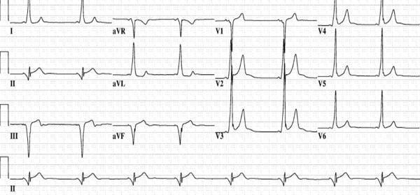
This diagnostic image is a 12-lead electrocardiogram (ECG) demonstrating the classic pre-excitation pattern of Wolff-Parkinson-White (WPW) syndrome associated with a posteroseptal accessory pathway. Key features include a shortened PR interval and the presence of delta waves—slurred upstrokes at the start of the QRS complexes. In the precordial leads, the delta wave is positive in V1, becomes less prominent in V2, and disappears by V3. Crucially, the delta waves are negative in the inferior leads (II, III, and aVF), mimicking a pseudo-infarct Q-wave pattern. This negative polarity in the inferior leads is highly suggestive of an accessory pathway originating in the posteroseptal region, potentially localized near the coronary sinus or middle cardiac vein. The tracing serves as an educational tool for medical students and electrophysiologists to practice electrocardiographic localization of bypass tracts prior to catheter ablation.
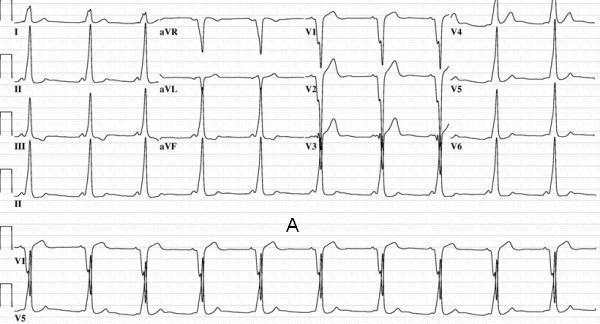
This Comparison Chart consists of two 12-lead electrocardiogram (ECG) tracings (Panel A and Panel B) demonstrating ventricular pre-excitation patterns characteristic of Wolff-Parkinson-White (WPW) syndrome. The primary educational focus is the localization of accessory pathways based on delta wave morphology. Panel A displays a patient with an anteroseptal accessory pathway, characterized by a short PR interval and wide QRS complexes with distinct slurred upstrokes. Specifically, delta waves are strongly positive in inferior leads (II, III, and aVF) and isoelectric to negative in lead V1. Panel B presents an ECG from a patient where the accessory pathway was successfully ablated in the supravalvular aortic cuspal region. Similar to Panel A, the inferior leads (II, III, aVF) show positive delta waves; however, lead V1 exhibits a slightly positive delta wave, distinguishing it from a true septal pathway. These images serve as a clinical diagnostic reference for electrophysiology, illustrating how subtle variations in precordial lead polarity can differentiate between septal and non-septal (paraseptal) accessory pathway locations.
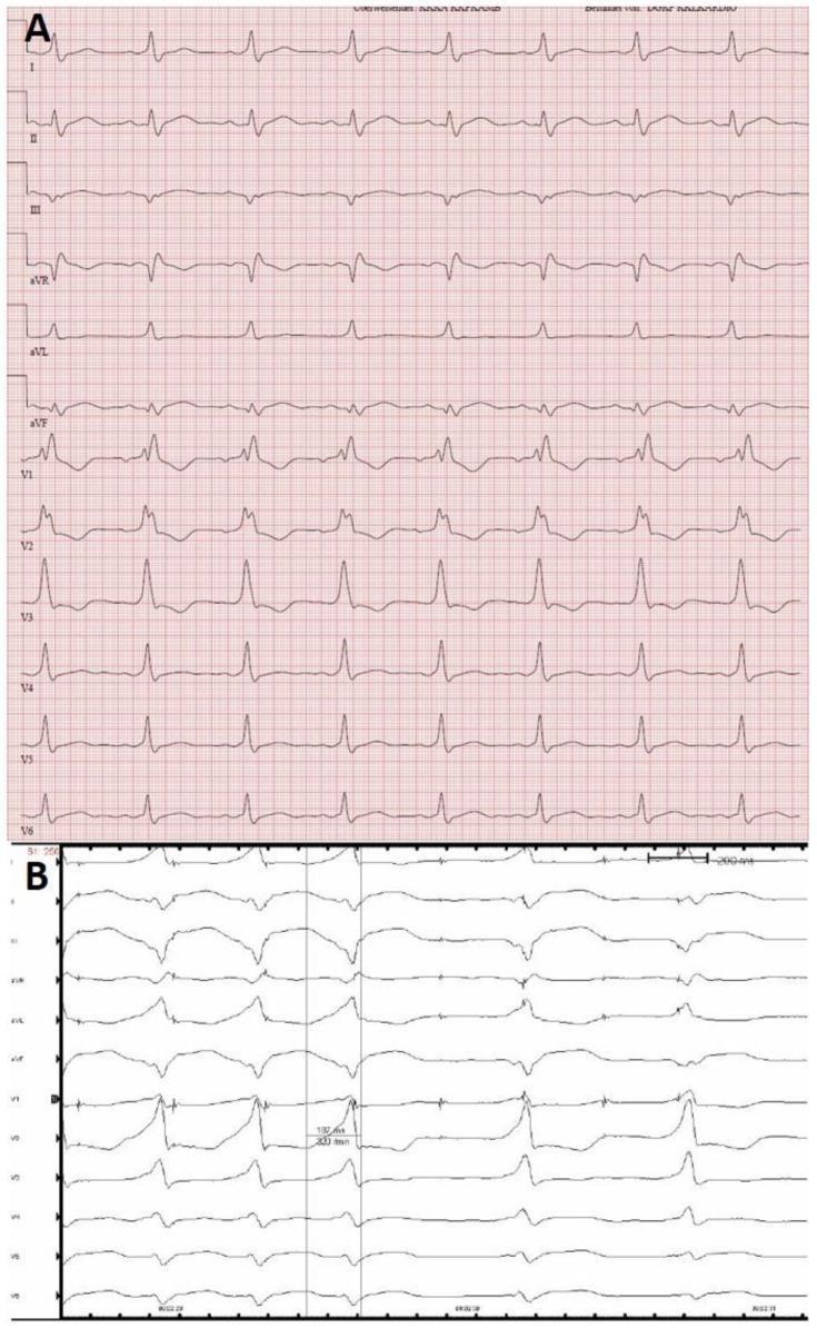
Two-part comparison of 12-lead electrocardiogram (ECG) tracings from a patient diagnosed with a left posterolateral accessory pathway (AP), illustrating Wolff-Parkinson-White (WPW) syndrome features. Panel A displays a standard resting ECG at a sweep speed of 50 mm/s. It exhibits manifest ventricular preexcitation characterized by short PR intervals and prominent delta waves, particularly visible in the precordial leads. Panel B shows an ECG recorded during an electrophysiology study (EPS) under rapid atrial pacing at a sweep speed of 100 mm/s. This maneuver induces full ventricular preexcitation, resulting in maximally widened QRS complexes and exaggerated delta wave morphology. The tracing demonstrates morphology shifts in the R/S ratios and QRS polarity, particularly in leads III, aVF, and V1-V2, which are diagnostic indicators used for the anatomical localization of the accessory pathway. The comparison highlights how pacing can accentuate preexcitation patterns for clinical assessment.
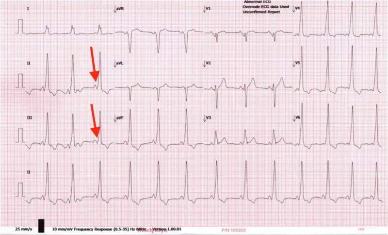
This diagnostic image is a 12-lead electrocardiogram (ECG) tracing demonstrating classic features of Wolff-Parkinson-White (WPW) syndrome. The primary finding is ventricular pre-excitation, characterized by a shortened PR interval (typically less than 120 ms) and a slurred upstroke of the QRS complex, known as a delta wave. Red arrows in leads II and III highlight these delta waves, which indicate early ventricular activation via an accessory pathway (Bundle of Kent). The QRS complexes are widened across multiple leads, particularly evident in the precordial leads V1-V3, and the rhythm is regular but appears tachycardic. The morphology of the QRS complexes in the limb leads and the prominent R waves in V1 are suggestive of an anteroseptal accessory pathway. This visual serves as a key educational resource for identifying pre-excitation patterns in cardiology and understanding the electrophysiological manifestations of accessory conduction pathways in pediatric and adult patients presenting with palpitations or syncope.
cardiac conduction system AV node bundle of His Purkinje accessory pathway diagram
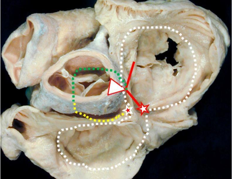
Anatomical Diagram over a clinical photograph of a gross cardiac specimen, viewed from the atrial aspect (superior view) of the cardiac base. The image illustrates the complex anatomy of the cardiac conduction system and vestigial embryonic structures. Key landmarks include the atrioventricular (AV) node (white star with red borders) and the retroaortic node (red star with white borders). The conduction pathway is delineated by a solid red line representing the bundle of His. Supplemental embryonic and auxiliary tracts are marked with dotted lines: a green dotted line shows the 'dead-end tract' continuing from the AV conduction axis toward the outflow tract; a yellow dotted line marks the retro-aortic ring branch; and a white dotted line traces the path of the embryonic atrioventricular ring. This visual is designed for advanced medical education in cardiac electrophysiology and embryology, highlighting the anatomical basis for idiopathic ventricular arrhythmias and the clinical significance of persistent embryonic tissues within the heart's conduction framework.
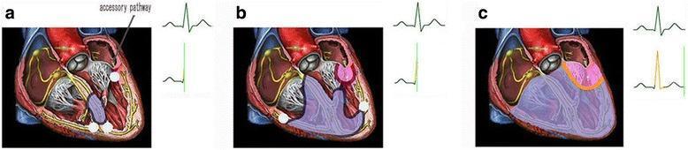
A three-part pathophysiology diagram illustrating the electrophysiological mechanism of incomplete latent preexcitation in the human heart, accompanied by representative ECG traces. Section (a) shows a cross-sectional view of the heart with a labeled accessory pathway (AP) connecting the atrium and ventricle. The normal conduction system (AV node and His-Purkinje system) is highlighted in yellow. The ECG shows a normal PR interval and QRS complex, indicating AV node conduction is faster than or equal to the AP. Section (b) illustrates the onset of ventricular preexcitation via the accessory pathway, marked by a pink-shaded activation region at the AP insertion point, while the corresponding ECG remains relatively normal. Section (c) depicts ventricular fusion where impulses from both the normal conduction system (purple) and the accessory pathway (pink) meet. This fusion results in a change to the terminal QRS vector and morphology on the ECG. The diagram serves as an educational tool for understanding Wolff-Parkinson-White (WPW) variants where preexcitation is not overt.
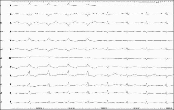
This diagnostic image is a 12-lead electrocardiogram (ECG) demonstrating the successful intraprocedural catheter ablation of an accessory pathway in a patient with Wolff-Parkinson-White (WPW) syndrome. The recording captures a transition between two distinct conduction states. The first four cardiac cycles exhibit classic pre-excitation features: a shortened PR interval and widened, slurred QRS complexes (delta waves) most prominent in leads V2-V5 and the inferior leads, indicating anterograde conduction across an accessory pathway. Following these beats, the subsequent four cycles show an immediate normalization of cardiac conduction post-ablation. These latter beats demonstrate a physiological PR interval and narrow, crisp QRS complexes, signifying that ventricular activation is occurring solely through the normal atrioventricular (AV) node-His-Purkinje system. This comparison serves as a definitive visual confirmation of the elimination of the bypass tract, which in this clinical context was associated with a high risk of malignant arrhythmias.
WPW Syndrome - Simplified but Complete
What Is WPW?
Normal Cardiac Cycle vs. WPW Cardiac Cycle
Normal (Understand this first)
SA Node → Atria (P wave)
         ↓
      AV Node ← Built-in DELAY here (allows atria to fully empty first)
         ↓
   Bundle of His → Bundle Branches → Purkinje Fibers
         ↓
   Ventricles contract rapidly (narrow QRS)
- PR interval: 0.12-0.20 s (delay at AV node)
- QRS: Narrow (fast, coordinated Purkinje spread)
WPW Cardiac Cycle
SA Node → Atria (P wave)
         ↓              ↓
    AV Node          Accessory Pathway (Bundle of Kent)
  (slow, delayed)    (FAST - no delay)
         ↓              ↓
  His-Purkinje       Ventricular muscle directly
  (arrives later)    (cell-to-cell, SLOW spread = DELTA WAVE)
              ↓
    Fusion QRS = delta wave + narrow terminal portion
- The accessory pathway jumps ahead of the AV node, "pre-exciting" part of the ventricle
- This creates the delta wave (slurred initial QRS upstroke) - Symptom to Diagnosis, p. 571
- The AV node catches up and completes the rest of the QRS via His-Purkinje (narrow terminal portion)
Classic ECG Triad
| Feature | Finding | Why |
|---|---|---|
| PR interval | Short (< 0.12 s) | Accessory pathway bypasses AV node delay |
| Delta wave | Slurred upstroke of QRS | Slow cell-to-cell spread from AP insertion |
| Wide QRS | > 0.10 s | Fusion of preexcited + normal conduction |
ECG Images
Accessory Pathway Locations and Axis
Pathway Locations (by frequency)
| Location | Frequency | Notes |
|---|---|---|
| Left free wall (mitral annulus) | ~60% | Most common |
| Septal (posteroseptal/anteroseptal) | ~25% | Near AV node region |
| Right free wall (tricuspid annulus) | ~15% | Common in Ebstein anomaly |
Delta Wave Polarity → Pathway Localization
| Pathway Location | V1 | Inferior leads (II, III, aVF) | Axis |
|---|---|---|---|
| Left posterior / posterolateral | Positive (R dominant) | Negative (looks like inferior MI) | Right axis or normal |
| Right anteroseptal | Negative or isoelectric | Positive | Left axis deviation |
| Posteroseptal | Positive | Negative | Superior axis |
| Left lateral | Positive | Positive | Normal to right axis |
-
Negative delta in V1 → right-sided or septal pathway
-
Positive delta in V1 → left-sided pathway
-
Negative delta in inferior leads → posteroseptal pathway (mimics inferior MI!)
-
Braunwald's Heart Disease, pp. 511-512
Preexcitation Pathway Diagram
Tachyarrhythmias in WPW
1. Orthodromic AVRT (most common, ~95%)
- Impulse goes DOWN the AV node/His-Purkinje → UP the accessory pathway (retrograde)
- Narrow QRS tachycardia (ventricles activated normally via Purkinje)
- Treat with: adenosine, beta-blockers, calcium channel blockers, or DC cardioversion
2. Antidromic AVRT (~5%)
- Impulse goes DOWN the accessory pathway → UP the AV node (retrograde)
- Wide QRS tachycardia (ventricles activated cell-to-cell from AP insertion)
- Treat with: DC cardioversion preferred; avoid AV node blockers
3. Pre-excited Atrial Fibrillation (MOST DANGEROUS)
- AF conducts down the accessory pathway directly (no AV nodal braking)
- Very rapid ventricular rates (R-R as short as 240 ms) → risk of ventricular fibrillation and sudden death
- NEVER give adenosine, digoxin, or verapamil - these block the AV node and push all conduction down the accessory pathway, accelerating ventricular rate
- Treat with: DC cardioversion or procainamide/ibutilide (slow the accessory pathway)
Concealed vs. Manifest Pathways
| Type | Conduction Direction | ECG at Rest | Delta Wave? |
|---|---|---|---|
| Manifest | Antegrade (atria → ventricle) | Short PR + delta wave | YES |
| Concealed | Retrograde only (ventricle → atria) | Normal sinus rhythm ECG | NO |
| Anterograde only | Antegrade only (~10% of pathways) | Short PR + delta wave | YES |
Summary: Simple Memory Map
WPW = Bundle of Kent (accessory pathway)
       ↓
Pre-excites ventricle before AV node signal arrives
       ↓
ECG: Short PR + Delta Wave + Wide QRS (fusion beat)
       ↓
Axis/Delta polarity tells you WHERE the pathway is:
  - Negative inferior leads → posteroseptal
  - Negative V1 → right-sided
  - Positive V1 → left-sided
       ↓
Arrhythmias:
  Orthodromic (narrow QRS) → most common
  Antidromic (wide QRS) → less common
  Pre-excited AF → MOST DANGEROUS (sudden death risk)
       ↓
Definitive treatment: Radiofrequency ablation