
Spine pedicals are Synovial joint
Spine Pedicles are NOT Synovial Joints
What a Pedicle Actually Is
The Actual Synovial Joints of the Spine
| Joint | Type | Notes |
|---|---|---|
| Zygapophyseal (facet) joints | True synovial joints | Formed by articular processes of vertebral arches; have articular cartilage, synovial membrane, and fibrous capsule |
| Costovertebral joints | Synovial joints | Ribs articulate with vertebral bodies via two synovial joints |
| Uncovertebral joints (of Luschka) | Synovial-like joints | Cervical spine only |
| Atlanto-axial joint | Synovial joint | Between C1 and C2 |
The Non-Synovial Joint of the Spine
Show me in picture
vertebra anatomy pedicle lamina labeled diagram
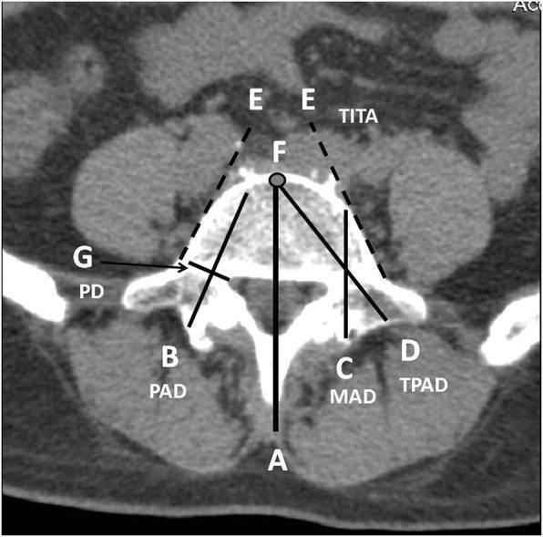
This diagnostic image is an axial computed tomography (CT) scan of a human lumbar vertebra, overlaid with a schematic diagram illustrating morphometric parameters essential for pedicle screw placement. The anatomical region focuses on the vertebral body, pedicles, and spinal canal. Key labeled parameters include: (A) the antero-posterior (AP) midline axis; (B) the longitudinal pedicle axis; and (G) the pedicle diameter (PD), measured perpendicular to the pedicle axis. Distance measurements shown include the Pedicle Axis Distance (PAD, line B), the Midline Axis Distance (MAD, line C) from the lamina to the anterior cortex, and the Transverse Pedicle Axis Distance (TPAD, line D) from the transverse process-pedicle interface to the anterior cortex. The Transverse Intertangential Angle (TITA) is formed by lateral tangential lines (E) along the vertebral body borders. Point F marks the anterior border of the midline axis, serving as the target endpoint for the Weinstein method of screw insertion. This educational diagram is used in orthopedic surgery and radiology to standardize measurements for safe surgical trajectories and to avoid iatrogenic complications.
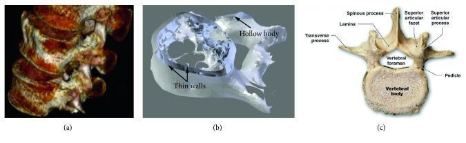
This composite educational image illustrates the transition from radiological data to digital modeling in spinal anatomy. Panel (a) presents a 3D CT reconstruction of the lumbar spine (L3-L5), showing the vertical alignment of vertebral bodies and posterior elements in a lateral view. Panel (b) displays a digital STL (Stereolithography) file of an L5 vertebra, highlighting a hollow internal structure and thin walls, representing a surface-based mesh approximation used in biomedical engineering. Panel (c) is a labeled anatomical diagram of a lumbar vertebra in a superior view. Key landmarks are identified, including the vertebral body, vertebral foramen, pedicle, lamina, spinous process, and transverse processes, as well as the superior articular facet and process. This comparison highlights the structural differences between biological anatomy, volumetric clinical imaging, and surface-based digital models used for 3D printing or surgical planning in orthopedics and regenerative medicine.
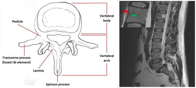
This educational composite compares anatomical structures of the human vertebrae through an anatomical diagram and magnetic resonance imaging. On the left, a coronal anatomical diagram labels the primary components of a single vertebra, including the vertebral body, vertebral arch, pedicle, lamina, spinous process, and transverse process (fused rib element). On the right, a sagittal T2-weighted MRI slice demonstrates the lumbar and lower thoracic spinal column. The MRI shows a sequential stacked configuration of rectangular vertebral bodies separated by intervertebral discs, exhibiting normal spinal curvature. An inset enlargement of one vertebral body uses color-coded arrows to highlight signal intensity variations: a red arrow indicates the cortical bone, which appears as a low-signal (dark) outer boundary, while a green arrow points to the cancellous bone/medullary space inside the vertebral body, characterized by a higher-signal (brighter) grayscale intensity. Posterior to the vertebral bodies, the high-signal cerebrospinal fluid within the spinal canal is clearly visible. This material is designed for medical students to understand spinal anatomy and T2-weighted radiological findings.
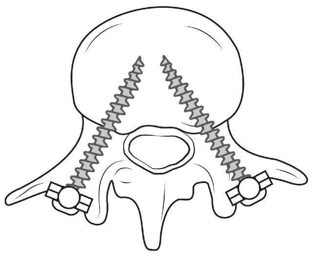
This schematic illustration depicts an anatomical diagram of a lumbar vertebra from a superior (axial) perspective, demonstrating bilateral pedicle screw placement (PSP). The diagram identifies key vertebral structures, including the large anterior vertebral body, the central vertebral foramen, bilateral pedicles, transverse processes, and the posterior spinous process. Two orthopedic screws are shown in situ, inserted through the pedicles on both the left and right sides. The trajectory of the screws is convergent, angling medially and anteriorly from the posterior entry points toward the center of the vertebral body to maximize purchase and stability. The screw heads are located posteriorly, featuring circular housings connected to short horizontal segments, representing the attachment points for longitudinal rods or plates used in spinal fusion procedures. This educational graphic serves to visualize the relationship between spinal instrumentation and vertebral anatomy, emphasizing the precise path required for safe and effective spinal stabilization.
facet zygapophyseal synovial joint spine anatomy
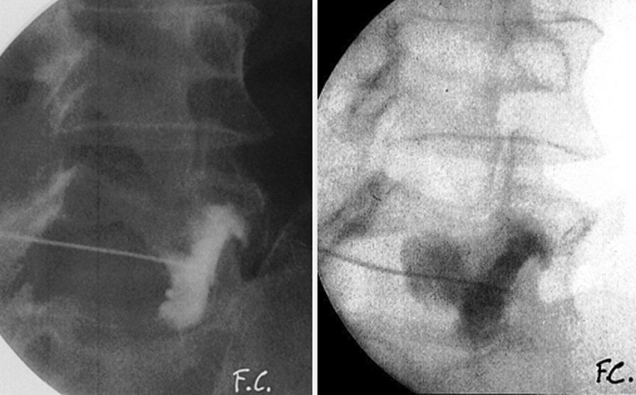
Two side-by-side fluoroscopic images in lateral view demonstrate a zygapophyseal (facet) joint infiltration in the lumbar spine. The images capture a needle or catheter precisely positioned for a percutaneous procedure. Following the injection of a radiopaque contrast medium, both frames reveal significant contrast extravasation extending beyond the expected anatomical borders of the joint capsule. This irregular pooling and flow pattern indicate a rupture of a synovial cyst (SC), confirmed by the loss of contained distribution within the joint space. The left image is presented with higher contrast, emphasizing the radio-dense contrast medium against the vertebral bodies, while the right image shows the same anatomy and pathology with a lighter exposure. The images are intended for educational demonstration of therapeutic synovial cyst rupture under fluoroscopic guidance, highlighting the visual cues for successful cyst decompression.
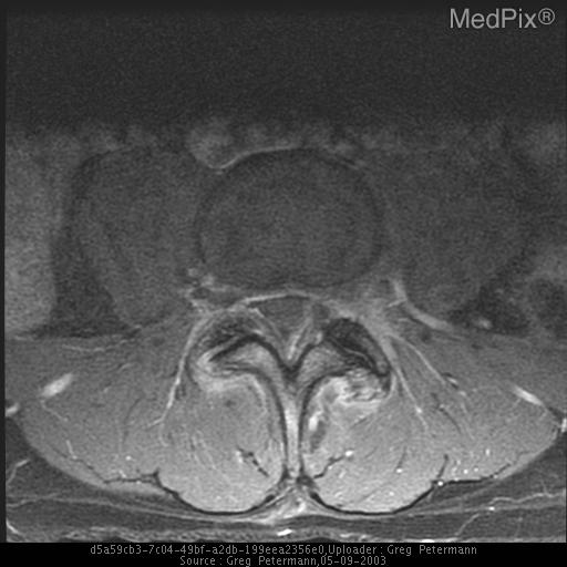
**Imaging Modality:** Axial Magnetic Resonance Imaging (MRI), T1-weighted sequence with contrast enhancement. **Anatomical Region:** Lumbar spine at the level of the facet joints. **Observed Pathology:** Bilateral lumbar synovial cysts originating from the zygapophyseal (facet) joints. **Characteristic Visual Features:** The image demonstrates bilateral, well-circumscribed cystic lesions located adjacent to the facet joints, extending into the spinal canal. The cysts exhibit a characteristic peripheral rim enhancement following contrast administration, indicating an inflammatory or vascularized capsule. There is associated facet joint hypertrophy and degenerative changes. The cysts exert mass effect on the thecal sac, resulting in narrowing of the central spinal canal (spinal stenosis). **Key Diagnostic Features:** - **Location:** Juxtafacet position, communicating with the joint capsule. - **Morphology:** Extradural cystic masses with rim enhancement. - **Impact:** Significant ventrolateral compression of the thecal sac and potential impingement of traversing nerve roots. **Clinical Significance:** These findings are characteristic of symptomatic degenerative spondylosis, frequently leading to radiculopathy or neurogenic claudication. This image is a primary reference for diagnosing spinal synovial cysts and assessing the degree of secondary canal stenosis.
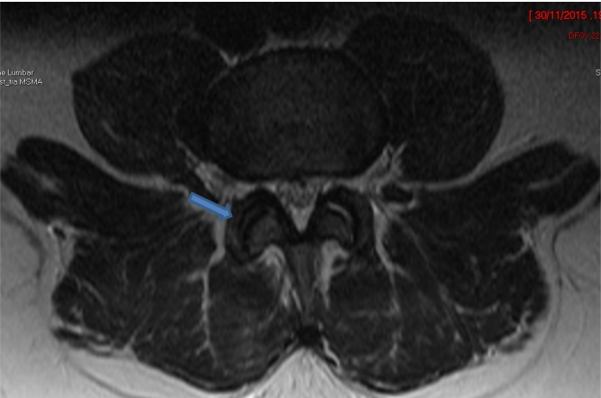
**Imaging Modality:** Magnetic Resonance Imaging (MRI), axial cross-section. **Anatomical Region:** Lumbar spine at the level of the posterior elements and facet joints. **Observed Findings:** The image displays the bilateral lumbar zygapophyseal (facet) joints. A blue arrow indicates the right-sided facet joint. There is an absence of significant joint effusion, synovial thickening, or surrounding soft-tissue edema. The articular surfaces appear regular with preserved joint space. No marrow edema is visualized in the adjacent pedicles or lamina, and the surrounding paraspinal musculature maintains normal signal intensity. **Clinical Context/Differentiating Features:** This follow-up scan demonstrates the resolution of inflammatory or infectious changes (septic arthritis). The lack of hyperintense signal on this T2-weighted or STIR-type sequence indicates a decrease in active inflammation and successful response to treatment. The spinal canal and neural foramina appear patent without evidence of compressive collections or epidural extension.
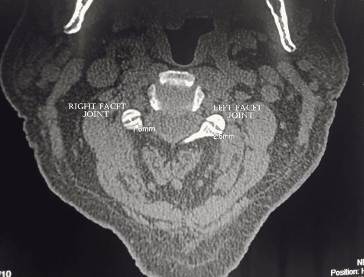
This diagnostic image is an axial Computed Tomography (CT) scan of the cervical spine, displaying the vertebral anatomy and associated soft tissues. Centrally, the vertebral body, spinal canal, and posterior elements including the lamina and spinous process are visible. The focus of the image is the bilateral facet joints (zygapophyseal joints). Annotations show measurement of the joint space width: the right facet joint measures 1.6 mm and the left facet joint measures 2.5 mm. Visually, the right facet joint exhibits signs of degenerative changes, including significant joint space narrowing and the presence of hypertrophic osteophytes. The left facet joint appears relatively more preserved but also shows mild irregularities. Surrounding the bony structures, the paracervical musculature and subcutaneous fat are visualized with varying attenuation. This image serves as an educational example of cervical facet arthropathy and the radiological assessment of spinal degenerative disease, specifically focusing on joint space measurements and osteophyte formation.
1. Vertebra Anatomy - Pedicle is a BONE, Not a Joint

2. Facet (Zygapophyseal) Joints - The ACTUAL Synovial Joints of the Spine
Key Takeaway from the Images
| Structure | What it is |
|---|---|
| Pedicle | Solid bone (part of vertebral arch) - connects body to lamina |
| Facet joint | True synovial joint - between articular processes of adjacent vertebrae |
| Intervertebral disc | Secondary cartilaginous joint (symphysis) - NOT synovial |
Facet are which type. Of Synovial joi t
types of synovial joints plane gliding classification diagram
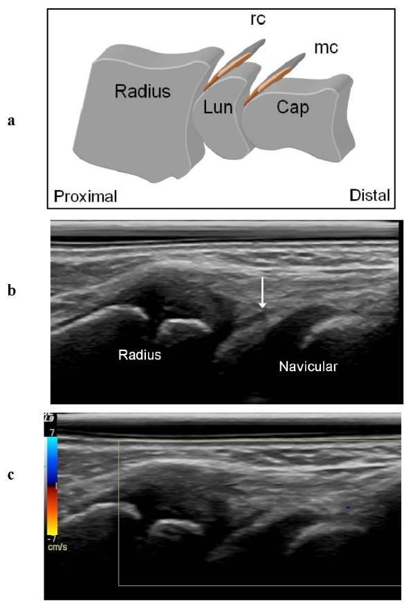
This composite educational graphic illustrates the normal ultrasonographic appearance of the dorsal wrist recesses. (a) An anatomical diagram in the sagittal plane shows the proximal-to-distal orientation of the radius, lunate (Lun), and capitate (Cap) bones, highlighting the dorsal synovial recesses of the radio-carpal (rc) and midcarpal (mc) joints. (b) A corresponding dorsal sagittal grey-scale ultrasound (US) scan demonstrates the thin, hypoechoic radio-carpal recess (indicated by a white arrow) situated between the distal radius and the navicular (scaphoid) bone. The bone surfaces appear as hyperechoic lines with posterior acoustic shadowing. (c) A color Doppler ultrasound image of the same region shows an absence of signal within the synovial recesses, indicating a lack of hyperemia, which is characteristic of a normal, non-inflamed joint state. These images serve as a clinical reference for distinguishing normal musculoskeletal anatomy from synovial hypertrophy or active synovitis in pediatric or adult patients.
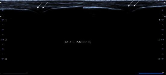
This grayscale ultrasound image displays a bilateral comparative view of the third metacarpophalangeal (MCP) joints in a transverse or longitudinal-oblique plane. The scan focuses on the dorsal aspect of the joints to evaluate the synovial space. White arrows in both the right (R) and left (L) panels highlight localized areas of hypoechoic tissue expansion within the joint recesses, signifying moderate synovial thickening. The echogenicity of this thickened synovium is relatively low (hypoechoic) compared to the overlying subcutaneous tissues and the hyperechoic surface of the underlying metacarpal bone. The presentation is classically consistent with Grade 2 synovitis, a key finding in inflammatory arthropathies such as rheumatoid arthritis or post-viral inflammatory syndromes. The bone cortex appears smooth without visible erosions, and the lack of color flow suggests a low-grade or non-hyperemic state if Power Doppler was applied. This image is used to teach MSK ultrasound findings for diagnosing active joint inflammation in clinical rheumatology.
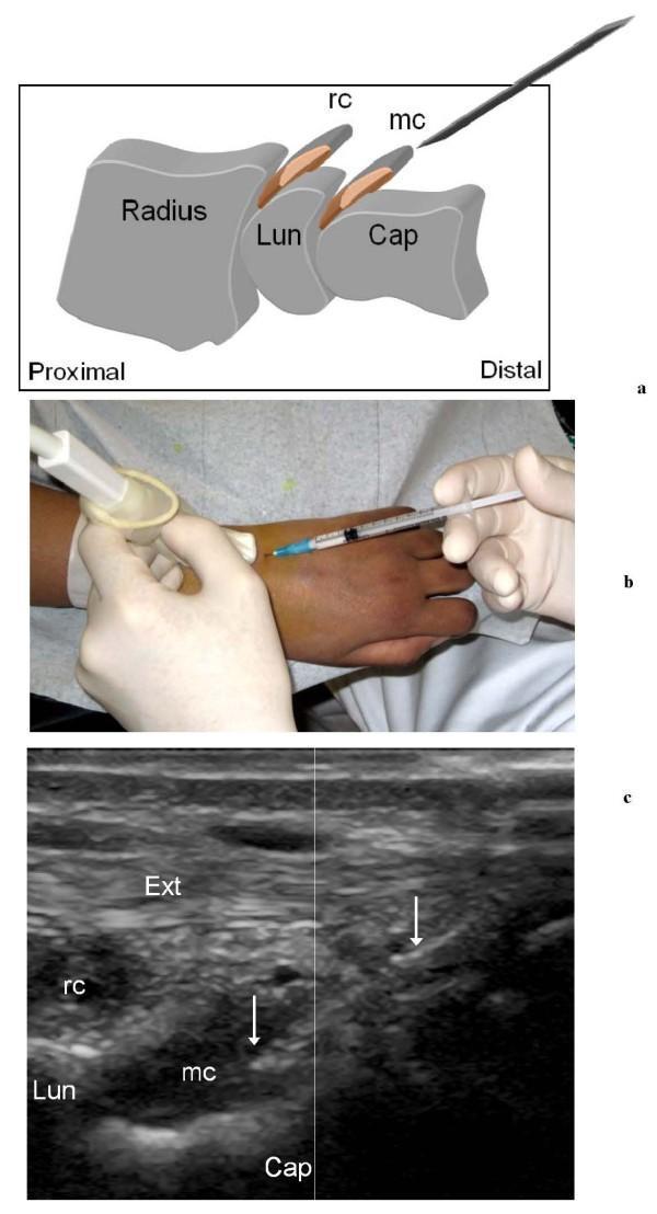
This composite educational graphic illustrates the technique for ultrasound (US)-guided puncture of the wrist joints in a patient with Juvenile Idiopathic Arthritis (JIA). Panel A provides an anatomical diagram in the sagittal plane, showing the radius, lunate (Lun), and capitate (Cap) bones. It highlights the dorsal radio-carpal (rc) and midcarpal (mc) recesses, indicating the proximal-to-distal needle trajectory. Panel B is a clinical photograph showing the procedural setup: a linear 'hockey-stick' transducer covered by a sterile sheath is held in a longitudinal orientation on the dorsal wrist, while a syringe and 23G needle are used for a free-hand puncture. Panel C displays a corresponding longitudinal sagittal US scan. In this sonogram, the extensor tendon (Ext) is visible superficially as a fibrillar, hyperechoic structure. Deeper, the hypoechoic bony cortex of the lunate (Lun) and capitate (Cap) are seen, with the midcarpal recess (mc) located between them. Hyperechoic linear echoes (arrows) represent the needle tip being successfully guided into the hypertrophic midcarpal synovial recess for corticosteroid injection.
facet joint zygapophyseal joint structure articular cartilage synovial membrane capsule diagram
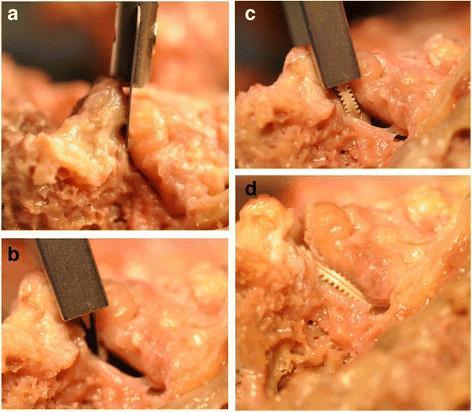
This set of clinical photographs (labeled a-d) illustrates the sequential steps of a major facet restoration procedure on a human cadaveric lumbar spine. The series demonstrates: a) Initial access to the zygapophyseal (facet) joint line using a surgical instrument; b) Mechanical distraction of the superior and inferior articular processes to widen the joint space; c) Insertion of a Glyder facet joint implant via a specialized delivery tool and cannula, showing the implant's characteristic ridged/toothed surface designed for stable fixation; and d) Final anatomical positioning of the implant within the joint space to maintain distraction and restore joint height. The facet capsule has been reflected for experimental visibility. This visual illustrates a minimally invasive surgical technique aimed at treating facetogenic back pain by restoring mechanical spacing and joint alignment in the posterior spinal column. Key anatomical landmarks include the articular cartilage surfaces and subchondral bone of the facet joint complex.
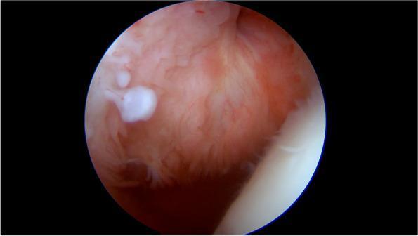
This arthroscopic clinical photograph captures an intra-articular view of the synovial membrane, likely within the shoulder joint. The primary finding is a well-defined, opaque, white cartilaginous body that is sessile, meaning it is directly attached to the underlying tissue without a stalk. The surrounding synovial membrane appears hyperemic and erythematous, characterized by a reddish-pink color and an irregular, frond-like or villous texture consistent with chronic synovitis. The border where the cartilaginous body arises from the synovia is somewhat irregular, showing a direct transition from the vascularized synovial tissue to the avascular hyaline cartilage structure. This visual representation is characteristic of primary synovial chondromatosis (PSC), a condition where the synovial lining undergoes metaplasia to form cartilaginous nodules. These nodules can eventually detach to become loose bodies within the joint space. The image serves as a clinical example of the early, attached phase of chondromatosis, demonstrating the macroscopic appearance and anatomical relationship between the metaplastic nodules and the inflamed synovial environment.
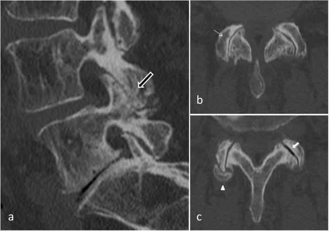
Diagnostic computed tomography (CT) scans of the lumbar spine illustrating hallmark signs of degenerative facet joint osteoarthritis (FJOA). View (a) is a sagittal reconstruction demonstrating significant hypertrophy of the posterior articular process (black arrow), which appears enlarged and sclerotic. Views (b) and (c) are axial images highlighting the bilateral synovial joints. Key diagnostic features shown include: 1) Joint space narrowing (thin white arrow in b), indicating loss of articular cartilage; 2) Vacuum phenomenon (white arrow in c), represented by intra-articular gas due to negative pressure within the degenerated joint; and 3) Joint capsule calcification (white arrowhead in c), appearing as dense, mineralized areas within the peripheral soft tissues. These findings collectively represent chronic degenerative changes in the 'three-joint complex' of the spinal segment, frequently associated with axial low back pain and mechanical instability.
Facet Joints = Plane (Gliding) Synovial Joints
Type of Synovial Joint
- Their articular surfaces are flat or slightly curved
- Movement is gliding/sliding in multiple directions
- They allow limited range of motion - mainly flexion, extension, lateral flexion, and rotation
- The degree of inclination of the articular surfaces varies by spinal region, which determines the specific movements allowed in each region
From the THIEME Atlas of Anatomy (textbook diagram):
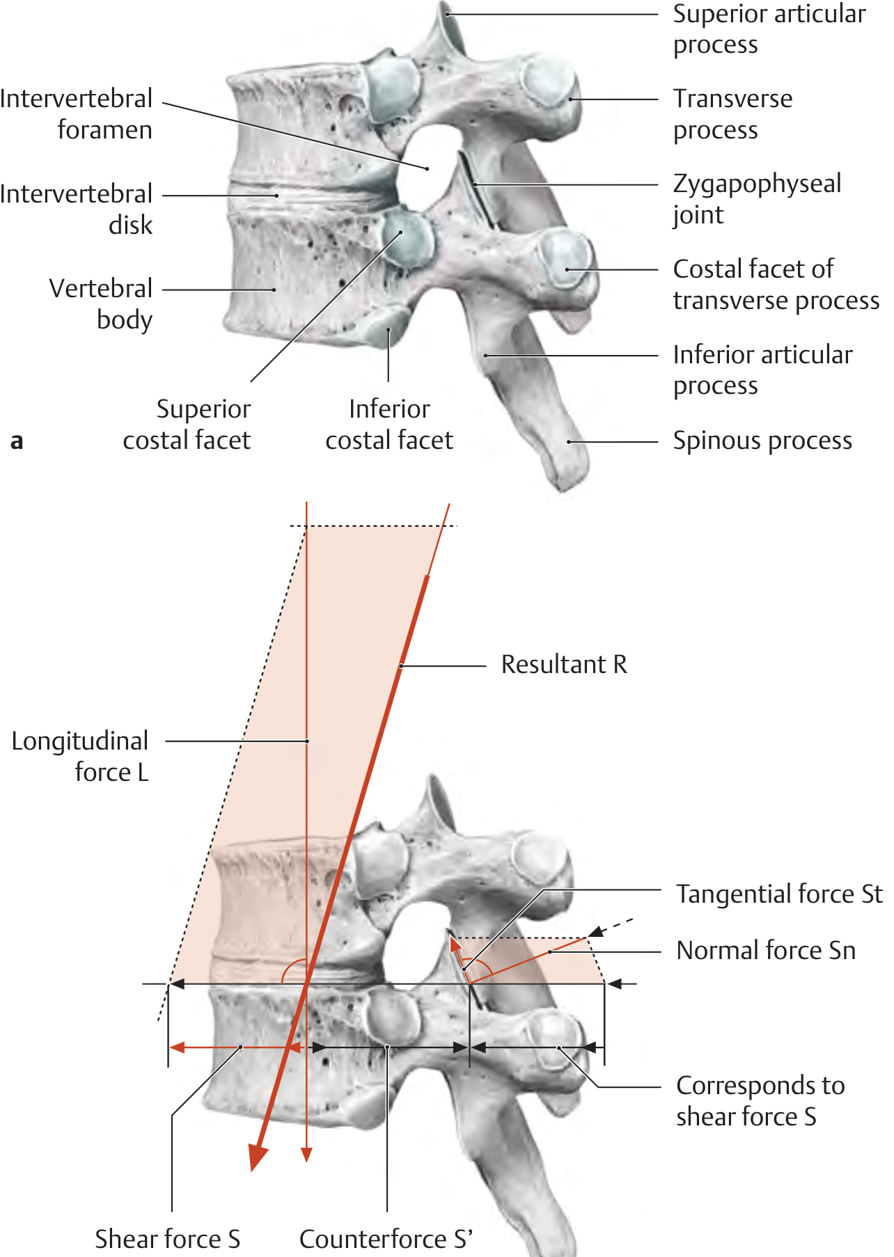
Components of the Facet Joint (making it a TRUE synovial joint)
| Component | Present in Facet Joint? |
|---|---|
| Hyaline articular cartilage | YES |
| Synovial membrane (lining) | YES |
| Joint capsule (fibrous) | YES |
| Synovial fluid | YES |
| Meniscoid synovial folds | YES (fills spaces around articular surfaces) |
| Ligamentum flavum attachment | YES |
"The paired facet joints are true synovial joints formed by the articular processes of the vertebral arches. Their articular surfaces show varying degrees of inclination from the horizontal in different spinal regions and are therefore specialized for certain directions and ranges of motion."
- THIEME Atlas of General Anatomy
How Facet Joint Orientation Differs by Region
| Spinal Region | Articular Surface Orientation | Movements Allowed |
|---|---|---|
| Cervical | Near horizontal (45°) | Flexion, extension, rotation, lateral flexion |
| Thoracic | Near vertical, coronal (60°) | Rotation > flexion/extension |
| Lumbar | Sagittal (vertical) | Flexion/extension > rotation (rotation is RESTRICTED) |