Provide an essay on titanium and its alloys for orthopaedic postgraduate exam
titanium alloys orthopaedic implants properties biomechanics
titanium corrosion osseointegration biocompatibility bone implants
Titanium and Its Alloys in Orthopaedic Surgery
Introduction
Metallurgy and Crystal Structure
- Alpha (α) phase: Hexagonal close-packed (HCP) structure, stable below 882°C (the beta transus temperature). It is stronger but less ductile.
- Beta (β) phase: Body-centred cubic (BCC) structure, stable above 882°C. More ductile and workable.
| Stabiliser Type | Examples | Effect |
|---|---|---|
| Alpha stabilisers | Aluminium (Al), Oxygen (O), Nitrogen (N) | Raise beta transus; strengthen α phase |
| Beta stabilisers | Vanadium (V), Molybdenum (Mo), Niobium (Nb), Iron (Fe) | Lower beta transus; stabilise β phase |
| Neutral | Zirconium (Zr), Tin (Sn) | Minimal phase effect; solid solution strengthening |
Classification of Titanium Alloys Used in Orthopaedics
1. Commercially Pure Titanium (CP-Ti) — ASTM Grades 1–4
- Contains 99–99.5% titanium with trace oxygen, nitrogen, carbon, iron, and hydrogen
- Four grades (1–4) of increasing oxygen content → increasing strength but decreasing ductility
- Grade 4 is the strongest CP-Ti grade
- Applications: Dental implants, porous coatings, uncemented acetabular shells, cardiovascular devices
- Yield strength: 170–480 MPa (Grade 1–4)
2. Ti-6Al-4V (Alpha-Beta Alloy) — The Workhorse
- Composition: 90% Ti, 6% Al, 4% V
- By far the most widely used titanium alloy in orthopaedics (~50% of all titanium alloy production)
- Al stabilises the α phase (solid solution hardening); V stabilises the β phase
- Available in two microstructural conditions:
- Annealed (standard): Balanced strength and ductility
- Extra Low Interstitial (ELI) — Ti-6Al-4V ELI: Reduced O, N, C, Fe content → superior fatigue life and fracture toughness; preferred for implants
- Yield strength: ~795–875 MPa; Ultimate tensile strength (UTS): ~860–965 MPa
- Applications: Hip stems, tibial trays, fracture plates, intramedullary nails, spinal rods, modular implant components
3. Ti-6Al-7Nb
- Developed as a vanadium-free alternative (concerns over vanadium cytotoxicity)
- Niobium replaces vanadium as β stabiliser
- Similar mechanical properties to Ti-6Al-4V
- Better corrosion resistance in chloride environments
- Applications: Hip prostheses (femoral stems), bone screws
4. Beta Titanium Alloys
| Alloy | Composition | Notable Properties |
|---|---|---|
| Ti-13Nb-13Zr | Ti-13%Nb-13%Zr | Low elastic modulus (~79 GPa), excellent corrosion resistance |
| Ti-12Mo-6Zr-2Fe (TMZF) | As named | High strength, low modulus |
| Ti-15Mo | Ti-15%Mo | FDA approved; low modulus, biocompatible |
| Ti-35Nb-7Zr-5Ta (TiOsteum) | As named | Ultra-low modulus (~55 GPa) |
| Ti-29Nb-13Ta-4.6Zr (TNTZ) | As named | Near bone modulus (~65 GPa) |
Key Physical and Mechanical Properties
| Property | Titanium (CP Grade 4) | Ti-6Al-4V ELI | Cortical Bone | Cobalt-Chrome | 316L Stainless Steel |
|---|---|---|---|---|---|
| Density (g/cm³) | 4.51 | 4.43 | 1.8–2.1 | 8.3–9.2 | 7.9 |
| Elastic modulus (GPa) | 104 | 114 | 10–30 | 210–253 | 193 |
| Yield strength (MPa) | 480 | 795–875 | 60–80 | 450–1000 | 170–750 |
| UTS (MPa) | 550 | 860–965 | 90–180 | 655–1200 | 465–950 |
| Fatigue strength (MPa) | ~300 | ~620 | — | ~600 | ~300 |
Biocompatibility and Osseointegration
Oxide Layer — The Key to Biocompatibility
- Is chemically inert and thermodynamically stable
- Has a thickness of approximately 2–10 nm under physiological conditions
- Acts as a physical barrier preventing ion release
- Reforms rapidly if damaged (self-passivation) — unlike stainless steel
- Promotes protein adsorption and cellular adhesion
Osseointegration
- Titanium oxide surfaces are osteoconductive
- Bone cells (osteoblasts) adhere, proliferate, and deposit mineral matrix directly on titanium surfaces
- No fibrous tissue layer intervenes (unlike many other metals)
- Surface modifications (see below) dramatically enhance the rate and quality of osseointegration
Surface Modifications
Physical/Mechanical Methods
- Sandblasting / grit-blasting: Creates macro-roughness (Ra 1–10 µm); promotes mechanical interlocking
- Shot peening: Induces compressive residual stress; improves fatigue strength
- Laser surface texturing: Precise micro/nano topography
Chemical Methods
- Acid etching (e.g. SLA — sandblasted + large grit acid etched): Creates micro-roughness that enhances osteoblast attachment
- Alkali and heat treatment (AHT): Produces sodium titanate layer; highly bioactive
- Hydrogen peroxide treatment: Produces microporous oxide layer
Coating Methods
- Plasma spray coating (titanium beads/mesh): Creates porous surface (pore size 100–400 µm); allows bone ingrowth; used on uncemented femoral stems and acetabular cups
- Hydroxyapatite (HA) coating: Bioactive calcium phosphate ceramic deposited by plasma spray; chemically bonds to bone; accelerates initial osseointegration
- Titanium plasma spray (TPS): Standard for many cementless implants
Porous Structures
- Trabecular metal (tantalum) is an alternative, but titanium foam and additively manufactured (3D-printed) titanium lattices now replicate trabecular bone architecture
- Elastic modulus of porous titanium can be tailored to match cortical or cancellous bone
Corrosion Behaviour
Types of Corrosion Relevant to Orthopaedics
- Uniform corrosion: Minimal with titanium due to oxide layer
- Galvanic corrosion: Occurs when two dissimilar metals are in contact in an electrolytic solution (e.g. titanium femoral head on cobalt-chrome taper — trunnion corrosion/trunnionosis)
- Crevice corrosion: In occluded spaces (modular junctions, screw-plate interfaces) where oxygen tension is low; can breach passive layer
- Fretting corrosion: Repetitive micromotion at modular junctions → mechanically assisted crevice corrosion (MACC)
- Pitting corrosion: Localised breakdown of oxide layer; less common with titanium than stainless steel
Galvanic Series in Physiological Saline (Most noble → Least noble)
Stress Shielding
- Wolff's Law: Bone remodels in response to mechanical stress. Reduced stress at the bone-implant interface leads to bone resorption.
- Despite titanium's lower modulus (~114 GPa for Ti-6Al-4V) compared to cobalt-chrome (~210 GPa) or stainless steel (~193 GPa), it is still 4–10 times stiffer than cortical bone (10–30 GPa).
- This mismatch leads to stress shielding, particularly:
- Proximal femoral bone loss around uncemented hip stems
- Cortical thinning around intramedullary nails
- Strategies to reduce stress shielding:
- Use of beta-titanium alloys (lower modulus ~60–80 GPa)
- Porous/lattice structures (tailorable stiffness)
- Anatomically shaped, flexible stem designs (e.g. isoelastic stems — historical concept)
- Composite stems (titanium with PEEK or carbon fibre)
Wear and Tribology
- High coefficient of friction
- Susceptibility to adhesive wear and abrasive wear
- Prone to fretting at modular junctions
- Generates titanium wear particles → macrophage activation → osteolysis (though titanium particles are generally less cytotoxic than cobalt-chrome ions)
- Titanium is NOT used as a bearing surface in total joint arthroplasty (not used for femoral heads or polyethylene-opposing surfaces)
- Cobalt-chrome or ceramic (alumina/zirconia) femoral heads are used against polyethylene in patients with titanium femoral stems
- Titanium screws on titanium plates can gall (cold weld) — anodisation or surface hardening is used to prevent this
Surface Hardening to Improve Wear Resistance
- Nitriding (gas nitriding / plasma nitriding): TiN surface layer; golden appearance; >2000 HV hardness vs ~300 HV for Ti-6Al-4V
- Oxidation hardening (BOXTM process): Produces thick oxide layer
- DLC (Diamond-like carbon) coating: Very hard, low friction
- Ion implantation: Nitrogen or oxygen ions implanted subsurface
Specific Clinical Applications
1. Total Hip Arthroplasty (THA)
- Femoral stem: Ti-6Al-4V (cementless); titanium plasma spray or HA-coated proximal coating promotes osseointegration
- Cobalt-chrome stems are used for cemented designs (better fatigue resistance in cement mantle)
- Acetabular shell: CP-Ti or Ti-6Al-4V; porous coating for press-fit fixation
- Titanium NOT used for femoral heads
2. Total Knee Arthroplasty (TKA)
- Femoral and tibial components predominantly cobalt-chrome
- Tibial tray may be titanium in some designs
- Tibial stems/augments: titanium alloy
3. Fracture Fixation
- Intramedullary nails: Ti-6Al-4V; lighter and more MRI-compatible than stainless steel; less stiff (reduces stress protection)
- Locking plates: Titanium alloy; preferred in osteoporotic bone and periarticular fractures
- External fixators: Titanium alloy pins and frames; MRI-compatible, lightweight
- Cannulated screws: CP-Ti or Ti-6Al-4V
4. Spinal Surgery
- Pedicle screws, rods, cages: Ti-6Al-4V predominates
- Titanium is MRI-compatible (minimal artefact compared to stainless steel)
- Porous titanium cages (3D-printed lattice): Allow bony ingrowth through cage body
- PEEK vs titanium cages: PEEK has near-bone elastic modulus but poor osseointegration; titanium integrates well but is stiffer
5. Shoulder and Elbow Arthroplasty
- Humeral components: titanium stems, cobalt-chrome heads
6. Osseointegrated Limb Prostheses (Percutaneous Implants)
- CP-Ti used for transcutaneous osseointegrated prostheses (OPRA system, OPL)
- Direct skeletal attachment for transfemoral and transtibial amputees
7. Paediatric Orthopaedics
- Elastic intramedullary nails (TENS): titanium; flexible, low stiffness preserves physeal growth
- Staples, 8-plates for guided growth: titanium
MRI Compatibility
- Titanium is paramagnetic — weak interaction with magnetic field
- Generates significantly less susceptibility artefact on MRI
- Does not deflect in MRI field (non-ferromagnetic)
- Allows high-quality post-operative imaging of periprosthetic soft tissues
- Stainless steel creates massive artefact and is conditionally MRI-safe
- Cobalt-chrome creates intermediate artefact
Adverse Biological Effects
Metal Ion Release
- The passive oxide layer severely limits ion release; titanium ion levels in periprosthetic tissue are extremely low
- However, in fretting/corrosion scenarios, titanium, aluminium, and vanadium ions are released
- Vanadium: Potentially cytotoxic, may inhibit phosphotyrosine phosphatases; reason for development of vanadium-free alloys (Ti-6Al-7Nb, Ti-13Nb-13Zr)
- Aluminium: Neurotoxic in high concentrations; reason for aluminium-free alloys in development
Titanium Particle Disease
- Macrophage phagocytosis of titanium wear debris → RANKL upregulation → osteoclast activation → periprosthetic osteolysis
- Titanium particles less pro-inflammatory than cobalt-chrome ions but cause osteolysis via particle burden
- Grey/black tissue discolouration (metallosis) around titanium implants
Hypersensitivity
- Titanium allergy is extremely rare (unlike nickel/cobalt-chrome hypersensitivity)
- Patch testing to titanium rarely positive
- CP-Ti preferred in patients with suspected metal sensitivity
Additive Manufacturing (3D Printing) of Titanium
- Electron Beam Melting (EBM) and Selective Laser Sintering/Melting (SLS/SLM): Can produce patient-specific implants with complex internal lattice structures
- Pore size, porosity, and strut geometry precisely controlled
- Elastic modulus of lattice implants can approach that of trabecular bone (~2–5 GPa)
- Applications: Custom acetabular cups, vertebral body replacement cages, tumour reconstruction implants, complex pelvic reconstructions
- Reduced material waste compared to subtractive manufacturing
Comparison with Other Orthopaedic Metals
| Feature | Ti-6Al-4V | Cobalt-Chrome (CoCrMo) | 316L Stainless Steel |
|---|---|---|---|
| Density (g/cm³) | 4.43 | 8.3–9.2 | 7.9 |
| Elastic modulus (GPa) | 114 | 210–253 | 193 |
| Corrosion resistance | Excellent | Good | Moderate |
| Biocompatibility | Excellent | Good | Good |
| Wear resistance | Poor | Excellent | Moderate |
| Osseointegration | Excellent | Moderate | Poor |
| MRI compatibility | Excellent | Moderate | Poor |
| Fatigue strength | Good | Excellent | Moderate |
| Cost | High | Moderate | Low |
| Suitable as bearing surface | No | Yes | No |
Failure Modes of Titanium Implants
- Fatigue fracture: Most common; titanium has a notch-sensitive fatigue behaviour; stress risers (screw holes, corrosion pits) accelerate fatigue
- Fretting corrosion at modular junctions: Trunnionosis in THA; modular neck fractures
- Peri-implant osteolysis: Secondary to titanium particle debris
- Galvanic corrosion: Mixing titanium with dissimilar metals (stainless steel screws in titanium plates)
- Aseptic loosening: Loss of osseointegration; less common with modern porous-coated designs
- Cold welding (galling): Titanium-on-titanium contact under load; thread locking during screw removal
Summary
- Excellent biocompatibility and spontaneous osseointegration due to the stable TiO₂ surface oxide
- Favourable strength-to-weight ratio (half the density of cobalt-chrome with adequate mechanical strength)
- Superior corrosion resistance through self-passivation
- MRI compatibility facilitating post-operative imaging
- Versatility across fracture fixation, arthroplasty, and spinal surgery
Provide an essay on TENS for orthopaedic postgraduate exam
titanium elastic nailing system TENS paediatric femur fracture technique
elastic stable intramedullary nailing ESIN children fracture fixation biomechanics
Titanium Elastic Nailing System (TENS) in Orthopaedic Surgery
Introduction
Historical Background
- 1980s: Métaizeau and Ligier, Nancy, France — developed the concept of elastic stable intramedullary nailing using stainless steel nails (originally called "ECMES" — embrochage centro-médullaire élastique stable)
- The system was subsequently refined using titanium due to its superior biocompatibility, elasticity, MRI compatibility, and ease of removal
- Gradually replaced traction and spica casting as the preferred operative treatment for paediatric femoral shaft fractures in school-age children
- Flynn et al. (J Bone Joint Surg Am, 2004) demonstrated superior outcomes with TENS compared with traction and spica casting (Treatment of Pediatric Diaphyseal Femur Fractures, p. 32)
Implant Design and Metallurgy
Material
- Composed of Ti-6Al-4V or commercially pure titanium (CP-Ti Grade 4)
- Titanium's properties make it ideal:
- Low elastic modulus (~114 GPa): provides flexibility and elastic recoil
- High yield strength: resists permanent deformation
- Excellent biocompatibility: TiO₂ passive oxide layer; no adverse tissue reaction
- MRI compatibility: minimal susceptibility artefact; facilitates post-operative imaging
- Ease of removal: low galling tendency compared to stainless steel
- Lightweight: density ~4.43 g/cm³
Nail Dimensions
- Diameter: Available in 2.0 mm, 2.5 mm, 3.0 mm, 3.5 mm, 4.0 mm, 4.5 mm
- Length: Customisable; cut to size intra-operatively
- Cross-section: circular (standard) or C-shaped (Nancy nail variant — provides rotational control)
- Pre-bent tip (the "swan neck" or "salmon hook" curve) facilitates intramedullary passage
Nail Selection — Rule of Thumb
- Nail diameter = 40% of the narrowest medullary canal diameter
- Two nails of equal diameter are used (one from each entry point)
- Combined cross-sectional area of the two nails should fill approximately 80% of the medullary canal at the isthmus
Biomechanical Principles
- Entry point cortex (at the nail insertion site)
- Fracture site (opposite cortex to entry)
- Metaphyseal/distal cortex (far end of nail)
- Symmetric three-point fixation in both the coronal and sagittal planes
- Axial load sharing (not load bearing) — preserves periosteal callus formation
- Resistance to bending in all planes when two nails are used
- Rotational stability (partial) — enhanced by nail pre-bending and cortical contact
Biomechanical Limitations
- TENS provides relative stability (not absolute) — micromotion at the fracture site stimulates secondary bone healing (callus formation), not primary bone healing
- Rotational and axial control are the weakest aspects of TENS — inadequate in comminuted, long oblique, or severely unstable fractures
- Does NOT provide rigid fixation — not suitable for pathological fractures or severe osteoporosis
Indications
Primary Indications (Strong Evidence)
- Diaphyseal femoral shaft fractures in children aged 5–11 years (Treatment of Pediatric Diaphyseal Femur Fractures, p. 7)
- Diaphyseal forearm fractures (radius and/or ulna) — both bones forearm fractures, displaced radial shaft fractures
- Humeral shaft fractures in older children
- Tibial shaft fractures — displaced diaphyseal fractures
Extended Indications
- Diaphyseal clavicle fractures (displaced, in adolescents)
- Subtrochanteric femoral fractures (with supplementary fixation)
- Pathological fractures through benign lesions (unicameral bone cysts)
- Osteogenesis imperfecta (OI) — "telescoping" or standard TENS for fracture fixation (Sofield-Millar combined)
Age Considerations for Femoral Fractures
| Age Group | Preferred Treatment |
|---|---|
| < 6 months | Pavlik harness / Gallows traction |
| 6 months – 5 years | Immediate spica cast (closed or with brief traction) |
| 5 – 11 years | TENS / Flexible IMN (strong evidence) |
| > 11 years / weight > 50 kg | Rigid IMN (piriformis/trochanteric entry) |
| Adolescent near skeletal maturity | Rigid IMN or dynamic compression plating |
Contraindications
Absolute
- Open physes with piriformis fossa entry (risk of AVN of femoral head) — TENS avoids this by entering at the distal femoral metaphysis
- Severely comminuted fractures — inadequate rotational/axial control
- Pathological fractures with aggressive lesions (primary bone malignancy)
- Morbid obesity (weight > 50 kg, or body weight > 10th percentile for age) — increased failure and malunion rates
Relative
- Long spiral or oblique fractures with > 25% cortical contact loss
- Subtrochanteric or distal metaphyseal-diaphyseal junction fractures (boundary zone — consider supplementary fixation)
- Open fractures Grade III (relative — external fixator may be preferred)
Surgical Technique — Femoral Shaft Fracture (Standard)
Pre-operative Planning
- Measure medullary canal diameter at the isthmus on AP and lateral radiographs
- Select nail diameter = 40% of narrowest canal diameter
- Plan entry points: typically distal femoral metaphysis, medial and lateral, approximately 2 cm proximal to the distal femoral physis
- Nail length: from entry point to the lesser trochanter/subtrochanteric region
Patient Positioning
- Supine on a radiolucent traction table or flat table
- Image intensifier (C-arm) available and draped for intra-operative fluoroscopy
- Traction (manual or table) applied to obtain fracture reduction
Step-by-Step Technique
- Lateral nail first: Small longitudinal incision (~1 cm) at the lateral metaphysis, 2 cm proximal to the lateral femoral condyle physis
- Awl or drill used to create an entry point in the cortex at 45° to the bone axis, directed proximally
- Nail pre-bent to a smooth curve (apex of curve = approximately the fracture site when nail is fully inserted)
- Nail introduced manually or with a T-handle, rotated 180° to navigate past the fracture
- Medial nail: Similarly introduced from the medial metaphysis
- Nails advanced under fluoroscopic guidance
- Crossed nails provide symmetric support
- Each nail tip should reach the proximal femoral metaphysis / greater trochanteric apophysis region — NOT into the femoral neck or physis
- Tips of both nails should be at the same level proximally — "bouquet" configuration
- Cut to leave 1–2 cm protruding from the cortex (facilitates removal)
- Burred or capped ends to prevent soft tissue irritation
- End caps available in some systems
Intra-operative Assessment
- AP and lateral fluoroscopy — confirm reduction, nail position, and symmetry
- Test rotational and angular stability clinically
- Check physis not violated at entry or tip
Post-operative Management
- Non-weight bearing initially, progressing to partial weight bearing with crutches at 4–6 weeks depending on callus formation
- Immobilisation: Some surgeons use a knee immobiliser or cast for 4–6 weeks in young/uncooperative children; older compliant children may mobilise without cast
- Radiographic review at 4, 8, and 12 weeks
- Union typically achieved by 8–12 weeks (femur); 6–8 weeks (forearm)
- Implant removal: Recommended at 1–2 years post-operatively, or once fracture fully healed, to prevent:
- Nail migration
- Physeal damage from retained nail
- Difficulty of removal if left long-term (cold welding)
Outcomes and Evidence
- Flynn et al. (2004) — JBJS Am: TENS superior to traction + spica casting; shorter hospital stay, faster return to normal activities, fewer complications related to immobilisation (Treatment of Pediatric Diaphyseal Femur Fractures, p. 32)
- Buechsenschuetz et al. (2002) — J Trauma: TENS vs. traction/casting — significantly shorter hospitalisation with TENS
- Strong evidence supports TENS for femoral shaft fractures aged 5–11 years (Treatment of Pediatric Diaphyseal Femur Fractures, p. 7)
- Poolman et al. (2006) — systematic review of 2422 paediatric femoral fractures: TENS consistently associated with good functional outcomes in appropriate age group
- Moroz et al. (2006) — JBJS Br: Predictors of complications with TENS — weight > 50 kg and fracture instability were the strongest predictors of complications and poor outcome (Treatment of Pediatric Diaphyseal Femur Fractures, p. 32)
Complications
Intra-operative Complications
- Physis violation: Nail tip or entry point encroaching on growth plate — may cause growth disturbance
- Fracture comminution during nail insertion — excessive force on an unstable pattern
- Inadequate reduction: Failure to achieve acceptable alignment before fixation
- Nail cross-over: Both nails entering same cortex
Early Post-operative Complications
- Malreduction / malunion:
- Angulation > 10° in any plane
- Rotation > 10°
- Shortening > 2 cm
- More common in unstable fracture patterns, heavy patients, and spiral/oblique fractures
- Skin/soft tissue irritation: From protruding nail ends — the most common complication; reduced by appropriate nail cutting and end caps
- Infection: Superficial wound infection at entry sites; rare deep infection
- Nail migration: Proximal or distal; may penetrate joint if unrecognised
Late Complications
- Leg length discrepancy:
- Overgrowth (most common in children < 10 years): hyperaemia from fracture stimulates physeal growth → typically 1–2 cm overgrowth
- Growth arrest: rare; related to physeal injury at entry point
- Refracture: After nail removal, especially if removed before consolidation
- Nail breakage: Rare; more common with undersized nails in heavy patients
- Joint stiffness: Particularly in forearm fractures — elbow and wrist stiffness
- Compartment syndrome: Related to the index fracture, not the fixation method
- Heterotopic ossification: Around entry sites — uncommon
Predictors of Complications (Moroz et al., 2006)
- Body weight > 50 kg — strongest predictor
- Fracture instability (comminution, long spiral patterns)
- Subtrochanteric or distal metaphyseal location
- Inadequate nail diameter (< 40% of canal)
TENS for Specific Fractures
Forearm Fractures (Both-Bone Forearm / Radius-Ulna)
- Indications: Displaced diaphyseal fractures in children > 5 years failing closed reduction, or unstable patterns
- Technique:
- Ulna: Retrograde nail from distal ulna (just proximal to distal ulnar physis); or antegrade from olecranon
- Radius: Retrograde nail from distal radius (proximal to Lister's tubercle, ulnar side); antegrade entry risks posterior interosseous nerve (PIN)
- Key principle: Restore radial bow — critical for forearm rotation
- Complications specific to forearm: PIN injury (antegrade radius), wrist pain from protruding distal end
Humeral Shaft Fractures
- Entry: Lateral or medial distal humerus (proximal to physis), retrograde
- Or: Proximal humerus (deltoid insertion level), antegrade
- Risk: Radial nerve injury (lateral entry); axillary nerve injury (proximal entry)
- Indication: Displaced, unstable humeral shaft fractures in children > 5 years
Tibial Shaft Fractures
- Entry: Proximal tibia metaphysis (medial and lateral, distal to tibial tuberosity apophysis)
- Or: Distal tibia — less common
- Indications: Displaced, unstable tibial diaphyseal fractures in school-age children
Subtrochanteric Femoral Fractures
- Technically challenging with standard TENS
- May require supplementary external fixator or proximal locking to control proximal fragment
- Alternative: Trochanteric entry rigid nail (piriformis fossa entry avoided due to AVN risk)
TENS vs. Other Treatment Options (Femoral Shaft, Age 5–11)
| Parameter | TENS | Spica Cast | External Fixation | Rigid IMN |
|---|---|---|---|---|
| Age group | 5–11 years | < 5 years | Any (open #, polytrauma) | > 11 years / > 50 kg |
| Hospitalisation | Short (1–3 days) | Short to moderate | Moderate | Short |
| Mobility | Early | Limited | Moderate | Early |
| Physis preservation | Yes | Yes | Yes | Trochanteric entry only |
| Rotational control | Partial | Poor | Good | Excellent |
| Comminuted fractures | Poor | Poor | Good | Good |
| Pin-track infection | No | No | Yes | No |
| MRI compatibility | Excellent | N/A | Limited | Moderate |
| Cost | Moderate | Low | High | Moderate-high |
| Evidence strength | Strong | Moderate | Moderate | Strong (older age) |
Acceptable Alignment Parameters Post-TENS (Femur)
| Parameter | Acceptable Limit |
|---|---|
| Varus/valgus angulation | ≤ 5° (< 5 years: ≤ 10°) |
| Anterior/posterior angulation | ≤ 10° |
| Malrotation | ≤ 10° |
| Shortening | ≤ 2 cm |
| Bayonet apposition | Acceptable in < 8 years |
Special Considerations
Pathological Fractures / Unicameral Bone Cysts (UBC)
- TENS provides fracture fixation AND acts as a splint across the cystic lesion
- Nails may be supplemented with steroid injection or bone graft
- "Three-and-four nail technique" described for UBC — fill cavity with multiple nails to provide structural support
Osteogenesis Imperfecta (OI)
- Standard TENS for acute fractures in mild OI (Type I)
- For severe OI with recurrent fractures: Telescoping nails (Sheffield, Fassier-Duval) preferred — elongate with growth
- TENS in OI: risk of cortical perforation due to thin, soft cortices
Polytrauma
- TENS suitable for isolated long bone fractures in the polytrauma child aged 5–11 years
- External fixation preferred if:
- Associated open fractures grade III
- Vascular injury requiring repair
- Severe soft tissue compromise
Summary
Essay on TENS( Transcutaneous Electric Nerve Stimulation) for orthopaedics postgraduate exam
transcutaneous electrical nerve stimulation TENS pain relief mechanism gate control theory
TENS clinical applications orthopaedic chronic pain physiotherapy evidence
Transcutaneous Electrical Nerve Stimulation (TENS) in Orthopaedic Surgery
Introduction
Historical Background
- 1965: Melzack and Wall published the Gate Control Theory of Pain — the theoretical foundation upon which TENS was later developed
- 1967: Wall and Sweet conducted early experiments using electrical stimulation for pain relief
- 1974: TENS devices became commercially available following FDA approval
- Initially developed as a screening tool to identify patients likely to respond to spinal cord stimulation (SCS) implants
- Rapidly adopted in physiotherapy and pain clinics for non-invasive pain management
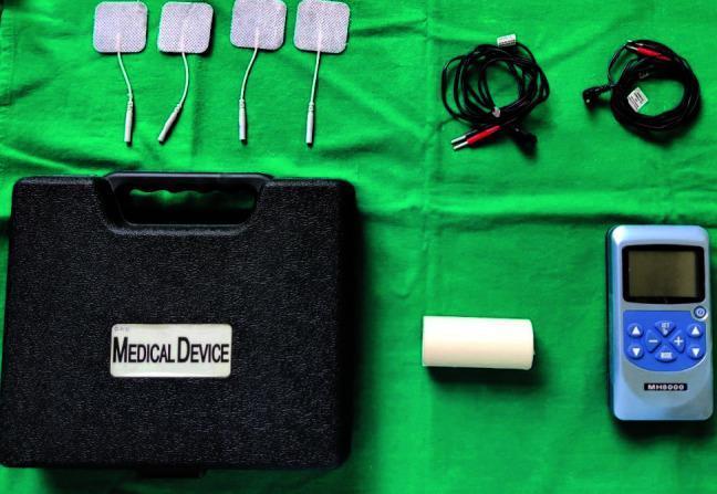
- Modern TENS units are compact, portable, battery-operated devices available for home use
Physics of TENS
1. Pulse Frequency (Rate)
- Measured in Hertz (Hz) — pulses per second
- High frequency (HF-TENS): 80–150 Hz — "Conventional TENS"
- Low frequency (LF-TENS): 1–10 Hz — "Acupuncture-like TENS"
- Burst mode: Trains of high-frequency pulses (typically 100 Hz) delivered at a low burst frequency (1–4 bursts/second)
2. Pulse Width (Duration)
- Measured in microseconds (µs)
- Typically 50–250 µs for conventional TENS
- Wider pulse width → greater depth of current penetration and larger fibre recruitment
- Narrower pulse width (50–80 µs) → selectively activates large diameter Aβ fibres
- Wider pulse width (200–300 µs) → recruits Aδ and motor fibres
3. Pulse Amplitude (Intensity)
- Measured in milliamps (mA)
- Typically 0–80 mA (adjustable to patient tolerance)
- Sensory threshold: Tingling sensation — activates Aβ fibres
- Motor threshold: Visible muscle contraction — activates Aδ and motor fibres
- Pain threshold: Intensity causing discomfort — avoided in most TENS protocols
4. Waveform
- Biphasic symmetric: Equal positive and negative phases — no net DC current; avoids skin burns; most common
- Biphasic asymmetric: Unequal phases; still charge-balanced
- Monophasic: Single polarity; carries risk of electrolytic skin damage; less commonly used
- Interferential current (IFC): Two medium-frequency (4000 Hz) alternating currents delivered through two separate channels; their interference generates a low-frequency beat within deep tissues
5. Electrode Configuration
- Channel: Two electrodes (anode + cathode) per channel; most devices have 1–2 channels (2–4 electrodes)
- Placement: Over painful area, along dermatomes, over peripheral nerves, trigger points, or acupuncture points
- Adequate electrode-skin contact essential; conductive gel or self-adhesive hydrogel electrodes used
Neurophysiological Mechanisms of Action
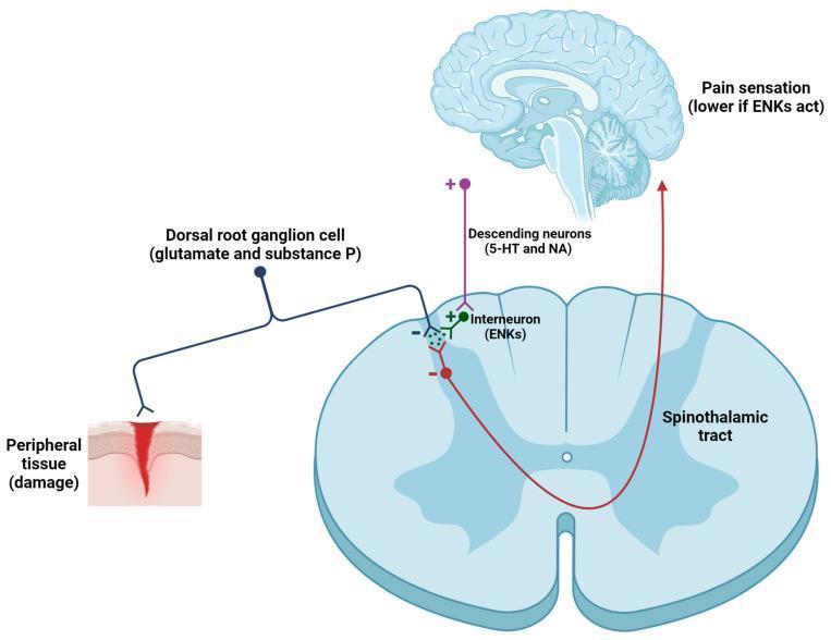
1. Gate Control Theory (Melzack and Wall, 1965)
- Pain signals are transmitted to the spinal cord via small-diameter, unmyelinated C fibres (slow, burning, chronic pain) and thinly myelinated Aδ fibres (fast, sharp pain)
- Non-painful sensations (touch, vibration, pressure) travel via large-diameter, myelinated Aβ fibres
- In the dorsal horn of the spinal cord (substantia gelatinosa, Rexed laminae I and II), a theoretical "gate" modulates transmission to the brain:
- Aβ fibre activity → activates inhibitory interneurons (substantia gelatinosa cells) → closes the gate → inhibits C and Aδ fibre transmission → reduces pain perception
- C and Aδ activity → inhibits the interneurons → opens the gate → facilitates pain transmission
2. Endogenous Opioid Release
- Low-frequency (1–10 Hz), high-intensity TENS recruits Aδ fibres and activates motor units
- This stimulates release of endogenous opioid peptides:
- Beta-endorphin: Released from the hypothalamus and pituitary; acts on µ-opioid receptors
- Enkephalins: Released in the spinal cord dorsal horn; acts on δ-opioid receptors
- Dynorphins: Released in the spinal cord; acts on κ-opioid receptors
- The analgesic effect of LF-TENS is:
- Blocked by naloxone (opioid receptor antagonist) — confirming opioid mediation
- Longer duration but slower onset than HF-TENS
- May cause muscle soreness due to motor recruitment
3. Descending Pain Inhibition
- Electrical stimulation activates supraspinal descending inhibitory pathways:
- Periaqueductal grey (PAG) → rostral ventromedial medulla (RVM) → dorsal horn
- Involves serotonergic and noradrenergic pathways
- Leads to widespread inhibition of nociceptive transmission
4. Peripheral Mechanisms
- Reduction in peripheral sensitisation: TENS may reduce release of pro-inflammatory neuropeptides (substance P, CGRP) from primary afferents
- Improvement in local circulation: Vasodilation through axon reflex and autonomic effects → reduces ischaemic pain
- Possible modulation of sodium channels: Reducing ectopic discharge from injured nerves
Summary Table of Mechanisms by TENS Mode
| TENS Mode | Frequency | Intensity | Primary Fibres | Mechanism | Onset | Duration |
|---|---|---|---|---|---|---|
| Conventional (HF) | 80–150 Hz | Low (sensory) | Aβ | Gate control | Rapid | Short |
| Acupuncture-like (LF) | 1–10 Hz | High (motor) | Aδ, motor | Opioid release | Slow | Prolonged |
| Burst mode | 1–4 bursts/s (100 Hz within burst) | Moderate | Aβ + Aδ | Gate + opioid | Moderate | Moderate |
| Intense TENS | 50–100 Hz | High (noxious) | Aδ, C | Counter-irritation (hyperstimulation) | Rapid | Short |
| Interferential | 4000 Hz carrier | Variable | Deep tissues | Gate control + circulation | Moderate | Moderate |
Modes of TENS Delivery
1. Conventional TENS (High-Frequency, Low-Intensity)
- Most widely used mode
- Settings: 80–150 Hz, pulse width 50–100 µs, low amplitude (sensory threshold — tingling, no muscle contraction)
- Onset: within minutes
- Duration of relief: limited to period of stimulation ± short post-stimulation period
- Suitable for: acute pain, post-operative pain, continuous use during activity
2. Acupuncture-like TENS (AL-TENS / Low-Frequency)
- Settings: 1–10 Hz, pulse width 100–300 µs, high amplitude (motor threshold — visible/palpable muscle twitching)
- Slower onset (20–30 minutes)
- Longer duration of relief (hours after cessation)
- Less well tolerated (muscle fatigue, soreness)
- Suitable for: chronic pain, patients who have developed accommodation to conventional TENS
3. Burst Mode TENS
- High-frequency bursts (100 Hz) delivered at low burst rate (1–4/second)
- Combines properties of conventional and AL-TENS
- Better tolerated than AL-TENS while still recruiting Aδ fibres
- Suitable for: chronic pain, patients who find continuous HF TENS uncomfortable
4. Intense TENS (Hyperstimulation)
- High frequency, high intensity, short treatment duration (< 15 minutes)
- Applied to acupuncture points, trigger points, or over peripheral nerves
- Counter-irritation mechanism (diffuse noxious inhibitory controls — DNIC)
- Suitable for: trigger point therapy, short procedures
5. Interferential Current Therapy (IFC)
- Technically distinct from TENS but related principle
- Two channels of medium-frequency AC (typically 4000 Hz) cross within tissues
- Beat frequency (0–150 Hz) created at intersection — equivalent to low-frequency stimulation at depth
- Advantage: medium-frequency carriers pass through skin impedance more easily → greater depth of penetration with less skin discomfort
- Used for: deep musculoskeletal pain, joint pain (knee, shoulder, hip)
Accommodation and Habituation
- Accommodation: Reduced neuronal response to sustained constant-frequency stimulation over time — patient feels diminishing sensation at the same TENS settings
- More pronounced with high-frequency continuous TENS
- Clinical solution:
- Modulated TENS: Continuously varying frequency, pulse width, or amplitude within set ranges
- Alternating between modes (HF → burst → LF)
- Increasing amplitude over time (patient-controlled)
- Switching electrode positions between sessions
Electrode Placement Strategies
| Strategy | Placement | Rationale | Best For |
|---|---|---|---|
| Over pain | Directly over painful area | Peripheral gating | Localised musculoskeletal pain |
| Dermatomal | Along dermatome of pain | Segmental inhibition | Radicular pain, referred pain |
| Peripheral nerve | Over known nerve trunk proximal to pain | Block large fibre pathway | Peripheral nerve injuries, limb pain |
| Trigger points | Over myofascial trigger points | Hyperstimulation | Myofascial pain syndrome |
| Acupuncture points | Traditional acupuncture loci | Opioid release | Chronic generalised pain |
| Motor points | Muscle motor point | Muscle pump, circulation | Oedema, ischaemic pain |
| Paravertebral | Adjacent to spine at relevant level | Segmental dorsal horn | Radiculopathy, back pain |
Clinical Applications in Orthopaedics
1. Low Back Pain (LBP)
- Marchand et al. (Level II evidence): TENS reduced pain intensity and unpleasantness significantly more than placebo-TENS immediately after treatment and at one week — but not at 3 or 6 months. Concluded TENS should be used as short-term treatment as part of a multidisciplinary programme for chronic LBP (Diagnosis and Treatment of Low Back Pain, p. 109).
- Epidural Interventions in Chronic Spinal Pain guidelines: "Due to this lack of optimal evidence TENS is not a treatment that is typically covered by insurance... Previous health technology assessments and society-led meta-analyses have found no benefit for TENS in patients with chronic pain" — though these meta-analyses have been criticised for paucity of RCTs and failure to compare TENS with other nerve stimulation therapies (Epidural Interventions in the Management of Chronic Spinal Pain, p. 29).
- Summary: TENS provides short-term relief in chronic LBP. Role as monotherapy is not supported; role within multimodal programmes is reasonable.
2. Osteoarthritis (OA)
- Knee OA: Multiple systematic reviews (Cochrane) — TENS provides statistically significant short-term pain relief vs. sham; unclear clinical significance
- TENS superior to placebo for immediate pain relief; effect size modest
- No disease-modifying effect; does not alter cartilage or joint structure
- Useful as adjunct to exercise, physiotherapy, and analgesia
- NICE guidelines (UK): Do not recommend TENS as a standalone treatment for knee OA (insufficient evidence for long-term benefit); acceptable as part of comprehensive pain management
3. Acute Post-operative Pain
- Several RCTs support TENS as an opioid-sparing adjunct following orthopaedic surgery
- Reduces pain scores and analgesic consumption following:
- Total knee arthroplasty (TKA)
- Total hip arthroplasty (THA)
- Spinal surgery
- Knee arthroscopy
- Applied to wound margins (avoiding open wound, staples, and sutures)
- Particularly useful in patients with opioid sensitivity, renal failure, or gastric ulcer (avoiding NSAIDs/opioids)
4. Fracture Healing and Bone Union
- Distinct from standard TENS: Pulsed electromagnetic field (PEMF) and direct current stimulation are more relevant
- However, TENS may provide pain relief during fracture rehabilitation
- Electrical bone stimulation (low-intensity DC or PEMF) — proven to enhance osteogenesis and used for delayed union and non-union — is mechanistically different from analgesic TENS
5. Shoulder Pain
- Rotator cuff tendinopathy, impingement, frozen shoulder (adhesive capsulitis)
- TENS reduces pain and improves range of motion as adjunct to physiotherapy
- Applied over deltoid, supraspinatus, or infraspinatus depending on pain distribution
6. Knee Pain
- Patellofemoral pain syndrome
- Post-meniscal surgery
- Quadriceps inhibition (electrical muscle stimulation/NMES — related modality): reduces post-operative quadriceps atrophy after TKA
7. Neck Pain and Cervical Radiculopathy
- TENS over cervical paraspinals and trapezius
- Short-term pain relief; evidence similar to LBP — short-term benefit, uncertain long-term effect
8. Peripheral Neuropathic Pain
- Diabetic peripheral neuropathy
- Post-herpetic neuralgia
- Complex Regional Pain Syndrome (CRPS)
- TENS provides symptomatic relief; does not modify the underlying neuropathy
9. Phantom Limb Pain
- Following amputation, TENS applied to residual limb or contralateral limb
- Evidence limited but some patients report meaningful relief
- Mechanism: possibly segmental inhibition at dorsal horn level
10. Tendinopathy and Soft Tissue Conditions
- Lateral epicondylitis (tennis elbow)
- Achilles tendinopathy
- Plantar fasciitis
- Role is adjunctive; no evidence of tendon healing effect
Practical Application Protocol
Assessment Before TENS
- Confirm indication and absence of contraindications
- Identify pain location, type (nociceptive vs. neuropathic), and distribution
- Document baseline pain score (VAS/NRS)
- Select appropriate mode based on pain chronicity and patient preference
Electrode Application
- Clean and dry skin
- Apply conductive gel or self-adhesive hydrogel electrodes
- Position electrodes per chosen strategy (see above)
- Minimum electrode size: 4 × 4 cm (larger for deeper structures)
- Electrode spacing: minimum 2.5 cm between electrodes on same channel
Treatment Parameters
- Session duration: 20–60 minutes (conventional); 20–30 minutes (AL-TENS)
- Frequency of sessions: Daily to twice daily for acute conditions; 3–5 sessions/week for chronic
- Amplitude: Increase until comfortable tingling (HF) or mild muscle twitch (LF)
- Patient education: Patients can self-administer home TENS safely
Contraindications
Absolute Contraindications
| Contraindication | Rationale |
|---|---|
| Cardiac pacemaker / implantable defibrillator | Electrical interference with device sensing/pacing — potentially fatal arrhythmia |
| Over anterior neck / carotid sinuses | May cause hypotension (carotid sinus stimulation), laryngospasm |
| Over pregnant uterus | Risk of uterine stimulation, premature labour |
| Epilepsy (transcranial application) | May precipitate seizures |
| Active haemorrhage / open wounds | May exacerbate bleeding |
Relative Contraindications
| Contraindication | Caution |
|---|---|
| Impaired skin sensation | Risk of burn; impaired ability to detect excessive current |
| Cognitive impairment | Patient cannot report discomfort |
| Malignancy | Avoid over tumour site (theoretical stimulation of tumour growth) |
| Deep vein thrombosis (DVT) | Avoid over affected limb (theoretical risk of embolisation) |
| Damaged or irritated skin | Dermatitis, psoriasis — skin injury risk |
| Metal implants | Generally safe with surface TENS — current does not concentrate around implants at standard TENS parameters; however, avoid direct placement over superficial metal hardware |
| Transcranially | Avoid in most patients; separate research field (tDCS) |
Adverse Effects
- Skin irritation / contact dermatitis: Most common — from electrode gel or adhesive; mitigated by electrode rotation and hypoallergenic gel
- Skin burns: Rare; caused by high current density (small electrodes, damaged gel), DC current, or prolonged application
- Muscle soreness: After AL-TENS (motor-level stimulation)
- Aggravation of pain: Occasionally, especially if electrodes misplaced over tender trigger points
- Electrical shock sensation: If amplitude increased too rapidly
Comparison with Related Electrophysical Modalities
| Modality | Mechanism | Depth | Best Application |
|---|---|---|---|
| Conventional TENS | Gate control (Aβ) | Superficial | Acute/subacute localised pain |
| AL-TENS | Endogenous opioids (Aδ) | Superficial-moderate | Chronic pain, acupuncture points |
| Interferential (IFC) | Gate + circulation | Deep | Deep joint/muscle pain |
| NMES / EMS | Motor nerve/muscle activation | Moderate | Muscle re-education, atrophy prevention |
| Ultrasound | Mechanical vibration, thermal | Deep soft tissue | Tendinopathy, scar tissue |
| LASER | Photobiomodulation | Superficial | Wound healing, tendinopathy |
| PEMF / bone stimulator | Electromagnetic induction | Bone | Non-union, delayed union |
| SCS (Spinal Cord Stimulation) | Dorsal column stimulation | Central | Failed back surgery, CRPS |
Evidence Summary and Limitations
What the Evidence Supports
- Short-term pain relief in chronic LBP, knee OA, neck pain, and post-operative pain — supported by multiple RCTs and systematic reviews
- Opioid-sparing effect in acute post-operative pain — supported by several RCTs
- Safe, non-invasive, inexpensive adjunct to multimodal pain management
Limitations of the Evidence
- Many RCTs are small, methodologically weak, and heterogeneous in TENS parameters, electrode placement, and outcome measures
- Placebo control is difficult: Sham TENS (no current) is detectable by patients who have previously used TENS — compromising blinding
- Variable TENS parameters across studies make pooled meta-analyses unreliable
- Long-term benefit remains unproven — most effects diminish after cessation of treatment
- Major health technology assessments and society meta-analyses have found no conclusive benefit for TENS in chronic pain (Epidural Interventions in the Management of Chronic Spinal Pain, p. 29), though criticised for methodological limitations
- TENS is often not covered by insurance due to uncertain long-term evidence base
Summary
Provide me diagrams on gate control pathway, central mechanism and parts of TENS to draw in exam
gate control theory pain pathway spinal cord dorsal horn diagram
TENS device components electrodes waveform diagram
gate control theory pain interneuron substantia gelatinosa transmission cell diagram
TENS — Diagrams to Draw in the Orthopaedic Postgraduate Exam
DIAGRAM 1 — The TENS Device and Its Components
How to Draw This in the Exam
┌─────────────────────────────────────┐
│         TENS CONTROL UNIT           │
│  ┌──────────────┐                   │
│  │  LCD SCREEN  │  [Pulse Rate Hz]  │
│  │  (display)   │  [Pulse Width µs] │
│  └──────────────┘  [Intensity mA]   │
│   [▲] [▼] [MODE] [ON/OFF]           │
│    CH1 ○──────────────────┐         │
│    CH2 ○──────────────────┤         │
└──────────────────────────┼──────────┘
                            │ lead wires
               ┌────────────┴────────────┐
           [Electrode]             [Electrode]
           (self-adhesive          (self-adhesive
            hydrogel pad)           hydrogel pad)
               +                         -
            (Anode)                  (Cathode)
Labels to Include on the Diagram
| Component | Key Points to Write |
|---|---|
| Control unit | Battery-powered; adjustable pulse rate (Hz), pulse width (µs), amplitude (mA) |
| LCD/display | Shows frequency, width, intensity settings |
| Channels (CH1, CH2) | Dual-channel unit = 4 electrodes; allows two separate treatment sites |
| Lead wires | Connect unit to electrodes; typically colour-coded |
| Self-adhesive electrodes | Hydrogel or conductive gel; minimum 4×4 cm; anode (+) and cathode (−) |
| Waveform output | Biphasic symmetric — no net DC current; prevents skin burns |
Waveform Diagram to Sketch Alongside
Biphasic Symmetric Waveform:

Amplitude
  +  │  ┌─┐     ┌─┐     ┌─┐
     │  │ │     │ │     │ │
  0 ─┼──┘ └──┬──┘ └──┬──┘ └──
     │       │       │
  -  │     ┌─┘     ┌─┘
     │     └─      └─
         ←——→
       Pulse width (µs)
     ←————————→
      Inter-pulse interval
     ←——————————————→
        1/Frequency (Hz)
DIAGRAM 2 — Gate Control Theory (Spinal Mechanism of TENS)
How to Draw the Gate Control Theory
        PERIPHERAL                    SPINAL CORD               BRAIN
        NERVOUS SYSTEM               (Dorsal Horn)

  Noxious         ──────[Aδ / C]────────►──────────────────────────► PAIN
  stimulus                              │    T cell              (Thalamus/
                                        │  (Transmission)         Cortex)
                                        │
  Touch /    ──────[Aβ]────────────►────┤
  TENS                             (+)  │
  stimulus                        SG cell ──(─)──►
                                 (Inhibitory
                                  interneuron,
                                 Substantia
                                  Gelatinosa)
Annotated Box Format (Exam-Ready)
┌────────────────────┐       ┌──────────────────────┐      ┌───────────┐
│  PRIMARY AFFERENTS │       │   DORSAL HORN         │      │   BRAIN   │
│                    │       │   (Spinal Gate)        │      │           │
│  Aβ fibres ───────►├──(+)──► SG cell (inhibitory   │      │ Pain      │
│  (large, myelinated│       │  interneuron) ──(─)──► T cell ─────────► │
│   touch/vibration/ │       │                        │      │ perceived │
│   TENS at 80-150Hz)│       │  T cell = Transmission │      │ or NOT    │
│                    │       │  cell (projects to     │      │           │
│  Aδ / C fibres ───►├──(+)──► spinothalamic tract)  │      │           │
│  (small, unmyelin- │  (─)  │                        │      │           │
│   ated; pain)      │       │  Aδ/C ──(−)── SG cell │      │           │
└────────────────────┘       └──────────────────────┘      └───────────┘
Key Rules of the Gate (write these as annotations):
| Input | Effect on SG Cell | Effect on T Cell | Gate | Result |
|---|---|---|---|---|
| Aβ activity (TENS) | Activated (+) | Inhibited (−) | CLOSED | Pain reduced |
| Aδ / C activity (pain) | Inhibited (−) | Activated (+) | OPEN | Pain perceived |
| TENS + pain | Aβ dominates | Inhibited | CLOSED | TENS analgesic |
DIAGRAM 3 — Central (Supraspinal) Mechanism of TENS
How to Draw This
         ┌─────────────────────────────────┐
         │            BRAIN                │
         │                                 │
         │  Cortex / Limbic system         │
         │        │                        │
         │  Periaqueductal Grey (PAG) ◄────┼── HF-TENS (Aβ activation)
         │        │                        │   LF-TENS (Aδ / opioid)
         │        ▼                        │
         │  Rostral Ventromedial           │
         │  Medulla (RVM)                  │
         │        │                        │
         └────────┼────────────────────────┘
                  │
                  │ Descending inhibitory tract
                  │ (Serotonergic 5-HT +
                  │  Noradrenergic NA fibres)
                  │
                  ▼
         ┌─────────────────────────────────┐
         │       SPINAL CORD               │
         │       Dorsal Horn               │
         │                                 │
         │  Interneuron releases:          │
         │  • Enkephalins (δ-receptors)    │
         │  • Dynorphins (κ-receptors)     │
         │  • β-Endorphin (µ-receptors)    │
         │        │                        │
         │        ▼ (−)                    │
         │  Inhibits T cell (transmission) │
         │  → Reduced spinothalamic output │
         └─────────────────────────────────┘
                  │
                  ▼
         REDUCED PAIN PERCEPTION
Neurotransmitters to Label
| Pathway | Neurotransmitter | Receptor | Blocked by |
|---|---|---|---|
| Descending (PAG→RVM→spinal) | Serotonin (5-HT), Noradrenaline (NA) | 5-HT, α₂ receptors | — |
| Spinal interneuron | Enkephalin | δ-opioid | Naloxone |
| Spinal interneuron | Dynorphin | κ-opioid | Naloxone |
| Hypothalamic/pituitary | β-Endorphin | µ-opioid | Naloxone |
DIAGRAM 4 — Summary Integration Diagram (All Three Mechanisms Together)
                    TENS ELECTRODES ON SKIN
                           │
                    Electrical current
                           │
          ┌────────────────┴─────────────────┐
          │                                   │
   HF TENS (80-150Hz)                 LF TENS (1-10Hz)
   Low intensity                      High intensity
   Sensory threshold                  Motor threshold
          │                                   │
   Activates Aβ fibres              Activates Aδ fibres
          │                          + muscle contraction
          │                                   │
          ▼                                   ▼
  SPINAL CORD                        SUPRASPINAL CENTRES
  Dorsal Horn                        (PAG, Hypothalamus)
          │                                   │
  SG interneuron                   β-Endorphin, Enkephalin
  activated (+)                     Dynorphin released
          │                                   │
  T cell inhibited (−)              Descending inhibition
  Gate CLOSED                       (5-HT, NA pathways)
          │                                   │
          └───────────────┬───────────────────┘
                          │
                   REDUCED PAIN SIGNAL
                   to Thalamus/Cortex
                          │
                          ▼
                  PAIN RELIEF (Analgesia)
Exam Drawing Tips
- Always label axes: In waveform diagrams, label X-axis (time, ms) and Y-axis (amplitude, mA)
- Use (+) and (−) symbols clearly for excitatory and inhibitory synapses — examiners look for this
- Name the cells: SG cell (Substantia Gelatinosa), T cell (Transmission cell), DRG (Dorsal Root Ganglion)
- Name the tracts: Spinothalamic tract (ascending pain), Corticospinal/reticulospinal (descending inhibition)
- Colour code if allowed: Red = pain fibres (Aδ/C); Blue = touch/TENS fibres (Aβ); Green = inhibitory interneurons
- Write the naloxone test as a footnote — demonstrates understanding of opioid mechanism
- Gate analogy: You may briefly write — "Gate open = pain perceived; Gate closed (by Aβ/TENS) = pain inhibited"