
Anaesthesia machine in two pages very short note all important points with hard words meaning
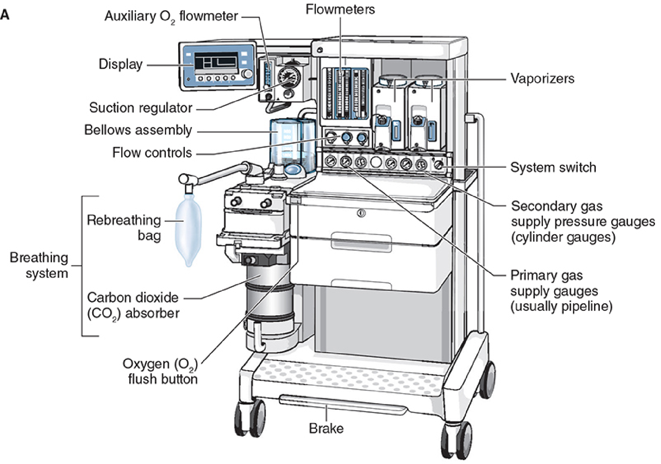
anaesthesia machine diagram components
This medical research diagram illustrates an experimental setup for a neuromuscular Brain-Machine Interface (BMI) using a non-human primate model. The illustration depicts a seated macaque performing manual reaching and grasping tasks in a 3D workspace. Key anatomical and technological components include: 1) Cortical recording: A 4x4 platinum electrocorticography (ECoG) electrode array is shown implanted over the left primary motor cortex (M1) to capture brain activity. 2) Muscle activity: Electromyography (EMG) electrodes are placed on the right arm to record intrinsic motor signals from muscle groups. 3) Kinematic tracking: Spherical position markers are attached to the arm and hand, linked to a 3D tracking system to measure joint angles (shoulder and elbow). 4) Behavioral interface: The setup features a 'Home' button and a 'Touch sensor' with a knob to facilitate reaching, pulling, and releasing movements. The diagram outlines the data acquisition pathway where neural and muscular signals are decoded to drive external devices, such as the indicated robotic arm, for rehabilitative or assistive technology research.
This schematic diagram illustrates a self-developed internal tocodynamometry machine used for monitoring fetal head descending thrust during labor. The illustration depicts three primary components: a pressure-sensitive sensor, a connecting rod, and an external monitoring unit. The sensor is shown in direct contact with the crown of a fetal head in the cephalic position, stabilized by a clinician's hand. A linear connecting rod, featuring three reinforcement bands, transmits the physical force from the sensor to the external device. The rectangular monitoring unit contains a display screen on the left and a circular dial with a cross-quadrant interface on the right. This diagnostic setup is designed to measure intrauterine pressure and fetal descent forces at specific stages of cervical dilation (3-5 cm, 5-8 cm, and 8-10 cm). The educational focus is on the instrumentation and clinical application of internal monitoring to assess labor progression and predict the necessity for emergency obstetric interventions.
Summary : This central illustration presents a multidisciplinary approach to cardiopulmonary bypass management, highlighting the integration of surgery, perfusion, and anaesthesia around the patient, supported by education, training, research, and clinical guidelines. diagram: # Central Structure : • The patient is depicted at the center, surrounded by three main disciplines: Surgery, Perfusion, and Anaesthesia. • These three disciplines form an inner ring around the patient. # Outer Segments : • Four colored outer segments encircle the inner ring, each representing a key supporting domain: – Red segment: Education, Academy, Quality Management, System Accreditation. – Yellow segment: Training, Continued Professional Development. – Green segment: Basic, Translational, and Clinical Research (with icons for laboratory, animal, and human research). – Teal segment: Development and Adoption of Clinical Practice Guidelines. # Icons & Visuals : • Each segment contains relevant icons: – Graduation cap for education. – Heart-lung machine for training. – Laboratory flask, mouse, and group of people for research. – Clipboard for clinical guidelines. • The inner disciplines have icons: surgical glove (Surgery), IV bag (Perfusion), stethoscope (Anaesthesia). # Supporting Organizations : • Logos of EACTAIC, EACTS, and The European Board of Cardiovascular Perfusion are shown at the bottom. # Text Elements : • Each segment lists its focus areas in bullet points. • The central ring labels the three disciplines and the patient. # Analysis : • The diagram visually emphasizes the patient-centered nature of cardiopulmonary bypass management. • It highlights the equal importance of surgery, perfusion, and anaesthesia, supported by education, training, research, and guidelines. • The multidisciplinary approach is reinforced by the interconnected rings and supporting domains, suggesting collaboration and integration among specialties. • The use of distinct colors and icons aids in quickly identifying each domain’s contribution.
Anaesthesia Machine - Short Note
Definition
Components - Overview (The "MSSVABC" Framework)
1. Medical Gas Supply
- Pipeline (primary) supply: Wall outlets deliver O₂, N₂O, air at ~50 psi (345 kPa). Color-coded connectors prevent gas mix-ups (O₂ = green/white; N₂O = blue; air = yellow).
- Cylinder (secondary) supply: High-pressure cylinders (O₂ = 2000 psi; N₂O = 745 psi) act as backup. Attached via Pin Index Safety System (PISS) - a pin-hole arrangement unique to each gas, preventing wrong cylinder attachment.
- Pressure regulators: Reduce high cylinder pressure to ~45 psi for safe use inside the machine.
Hard words:
- Pipeline = hospital wall gas supply system
- Psi = pounds per square inch (pressure unit)
- PISS = Pin Index Safety System (prevents wrong gas cylinder attachment)
2. Safety Devices
- Fail-safe valve (= oxygen supply failure safety device): Cuts off N₂O and other gases if O₂ pressure falls below a threshold - prevents delivery of a hypoxic (low-oxygen) mixture to the patient.
- Proportioning system (e.g., Link-25): Mechanically links N₂O and O₂ flowmeters to ensure a minimum of 25% O₂ in the delivered mixture at all times.
- Oxygen flush valve: Delivers 100% O₂ directly to the breathing circuit at 600-1200 mL/sec. Must NOT be used during the inspiratory phase of mechanical ventilation (risk of barotrauma - lung injury from excess pressure).
Hard words:
- Hypoxic mixture = gas with dangerously low oxygen concentration
- Barotrauma = lung injury caused by excessive airway pressure
- Fail-safe valve = automatically shuts off gas if O₂ pressure is lost
3. Flowmeters (Rotameters)
- Glass tubes containing a bobbin/float that rises according to gas flow rate (measured in L/min).
- O₂ flowmeter is always positioned downstream (last, closest to patient outlet) so any leak in another gas tube does not contaminate the O₂ stream.
- Modern machines use electronic gas flow control instead of traditional rotameters.
Hard words:
- Rotameter = a type of variable-area flowmeter using a float inside a tapered tube
- Bobbin = the float inside the rotameter tube
4. Vaporizers
- Convert liquid volatile anaesthetic agents (sevoflurane, isoflurane, desflurane, halothane) into vapour and add them to the fresh gas flow.
- All modern vaporizers are:
- Agent-specific (each drug has its own color-coded vaporizer)
- Temperature-compensated (deliver constant concentration regardless of ambient temperature changes)
- Variable-bypass type: Fresh gas is split - a portion (the "bypass" flow) bypasses the vaporizing chamber, while a smaller portion picks up anaesthetic vapour; both recombine at the outlet.
- Desflurane vaporizer is a special electrically-heated pressurized unit (desflurane boils near room temperature at ~23°C, so a standard vaporizer cannot be used).
- Interlock system: Only one vaporizer can be turned on at a time - prevents simultaneous delivery of two agents.
Hard words:
- Volatile anaesthetic = liquid anaesthetic that easily evaporates at room temperature
- Vapour pressure = pressure exerted by a liquid's evaporated molecules
- Variable bypass = mechanism splitting gas flow between bypass channel and vaporizing chamber
- Temperature-compensated = automatically adjusts output despite temperature change
- Agent-specific = designed for only one drug, not interchangeable
5. Breathing Circuit (Circle System)
| Component | Function |
|---|---|
| Fresh gas inlet | Entry point of gas from machine |
| Inspiratory one-way valve | Allows gas flow only toward patient |
| Y-piece | Connects circuit to patient's endotracheal tube/mask |
| Expiratory one-way valve | Directs exhaled gas away from patient |
| CO₂ absorber canister | Contains soda lime/barium hydroxide to absorb CO₂ |
| APL valve (Adjustable Pressure-Limiting valve) | Vents excess gas during spontaneous/manual ventilation |
| Reservoir bag (rebreathing bag) | Acts as a buffer; also used for manual (bag) ventilation |
Hard words:
- Rebreathing = patient re-inhales previously exhaled gas (after CO₂ removal)
- Soda lime = CO₂ absorbing granules (NaOH + Ca(OH)₂); turns purple/white when exhausted
- APL valve = pressure-relief valve; "pop-off" valve; limits maximum circuit pressure
- Circle system = closed/semi-closed breathing circuit with CO₂ absorber
6. Ventilator
- Mechanically inflates the patient's lungs when spontaneous breathing is suppressed by anaesthesia/muscle relaxants.
- Types:
- Bellows (pneumatically-driven): A bellows (accordion-like bag) compressed by a driving gas (O₂ or air); ascending bellows (rise on expiration) are safer as they reveal leaks.
- Piston ventilator (electrically driven): More accurate tidal volumes; better for patients with poor lung compliance and for paediatric patients.
- Turbine ventilator: Uses an electrically driven turbine; no external driving gas needed.
- Double-circuit system: Driving gas circuit and patient gas circuit are separate.
- Spill valve: Closed during inspiration; excess gas exits during expiration.
- Low peak inspiratory pressure
- Low exhaled tidal volume
- Low exhaled CO₂ (capnography)
Hard words:
- Compliance = stretchability of the lungs (reduced in fibrosis, ARDS)
- Bellows = collapsible bag-like chamber used to push gas
- Tidal volume = volume of gas delivered per breath (~6-8 mL/kg)
- Pneumatically driven = powered by compressed gas
7. Scavenging System (Waste Gas Scavenger)
- Collects excess/waste anaesthetic gases vented from the APL valve and ventilator spill valve.
- Removes gases from the operating room to protect theatre personnel from chronic exposure.
- Types: active (uses wall suction) and passive (relies on pressure gradient).
- Pollution of the OR with anaesthetic gases is a chronic occupational health hazard - linked to reproductive toxicity, hepatotoxicity, and neurological effects in theatre staff.
Hard words:
- Scavenger = system that collects and removes waste gases
- APL valve = adjustable pressure-limiting (pop-off) valve
- Occupational hazard = health risk related to workplace exposure
Machine Pre-Use Checkout (FDA Checklist Principles)
- Verify oxygen analyzer calibration
- Perform low-pressure circuit leak test (tests vaporizers and downstream components)
- Check pipeline pressure gauges (should read ~50 psi)
- Test fail-safe valves and O₂ flush
- Evaluate circle system integrity
- Confirm ventilator function and alarms
- Check CO₂ absorbent color (must NOT be exhausted)
Key Safety Points
- Equipment failure is rare - most adverse outcomes are due to operator error (unfamiliarity with machine or failure to check before use) - accounts for ~1% of ASA Closed Claims cases.
- O₂ flowmeter must be last (downstream) to prevent hypoxic gas delivery.
- O₂ flush during mechanical ventilation inspiration can cause fatal barotrauma (600-1200 mL/sec surge with APL valve excluded).
- Always use an ascending bellows ventilator - a leak causes the bellows to collapse visibly (patient safety indicator).
- Soda lime exhaustion signs: colour change to violet/white, patient shows rising ETCO₂ (end-tidal CO₂) on capnograph.
Quick Glossary of Hard Words
| Term | Meaning |
|---|---|
| Workstation | Modern all-in-one anaesthesia machine with monitors and microprocessors |
| Volatile anaesthetic | Liquid drug that evaporates easily (e.g., sevoflurane, isoflurane) |
| Vaporizer | Device that converts liquid anaesthetic to vapour at a set concentration |
| Rotameter/Flowmeter | Device measuring gas flow in L/min using a float in a glass tube |
| APL valve | Adjustable Pressure-Limiting valve - vents excess gas from circuit |
| Barotrauma | Lung damage caused by excessive pressure |
| Hypoxic | Having dangerously low oxygen |
| Compliance (lung) | Ability of lungs to stretch and expand |
| Soda lime | CO₂-absorbing granules in the circle system |
| ETCO₂ | End-tidal CO₂ - CO₂ concentration at end of exhalation (normal ~35-45 mmHg) |
| Bellows | Collapsible ventilator bag that squeezes to deliver a breath |
| Scavenging | Removal of waste anaesthetic gas from the operating theatre |
| Proportioning system | Mechanical link ensuring O₂ is never below 25% in gas mixture |
| Fail-safe valve | Shuts off N₂O/air if O₂ supply fails |
| PISS | Pin Index Safety System - prevents wrong gas cylinder attachment |
| Tidal volume | Volume per breath (~6-8 mL/kg body weight) |
| Capnography | Continuous monitoring of CO₂ in exhaled breath |
| Pneumatically driven | Powered by compressed gas |
| Agent-specific | Vaporizer designed for only one anaesthetic drug |