
Guided Endodontics pdf for 10marks question
guided endodontics 10 marks question answer procedure CBCT drill guide
https://www.slideshare.net/slideshow/15-guided-endodontics-i…
https://pmc.ncbi.nlm.nih.gov/articles/PMC12747600
guided endodontics CBCT drill guide calcified canal
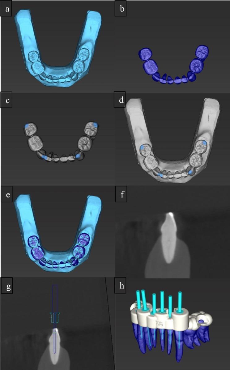
This composite image illustrates the digital workflow for static guided endodontics in managing calcified root canals. Subfigures (a) and (b) show the initial data acquisition via an intraoral scan (IOS) of a mandibular arch and a segmented Cone Beam Computed Tomography (CBCT) dental model. Panels (c), (d), and (e) demonstrate the registration and superimposition of these data sets within dental planning software, allowing for high-precision anatomical mapping. Subfigures (f) and (g) provide cross-sectional radiographic views showing the virtual planning of an access cavity; (g) specifically depicts a virtual drill path oriented toward the orifice of a calcified root canal to ensure a straight-line access. Panel (h) presents the final 3D design of a surgical template (endodontic guide) positioned over the dental arch. The template features sleeves and light blue cylinders representing the trajectory and depth control for the guided burs. This pedagogical visual summarizes the transition from diagnostic imaging to computer-aided design (CAD) for minimally invasive endodontic procedures.
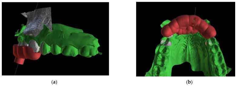
This diagnostic composite image displays a 3D digital planning model for guided endodontics, created by merging Cone Beam Computed Tomography (CBCT) DICOM data with intraoral scan STL files. The visualization depicts a maxillary dental arch in green, highlighting the anatomical crowns and gingival architecture. Superimposed in red is a custom, teeth-supported endodontic guide or template. View (a) shows the labial aspect, illustrating the guide's extension over the anterior teeth and a built-in cylindrical sleeve designed to dictate the path of a high-speed drill or endodontic file toward a calcified root canal. A metallic, textured 3D reconstruction of the bone or radiographic marker is visible superior to the teeth. View (b) presents the palatal/occlusal aspect, demonstrating the horseshoe-shaped template's stable seating across multiple teeth and its relationship to the palatal vault. A thin line indicates the planned virtual trajectory for precise access, intended to minimize tooth structure loss and prevent perforation during the localization of obliterated root canals.
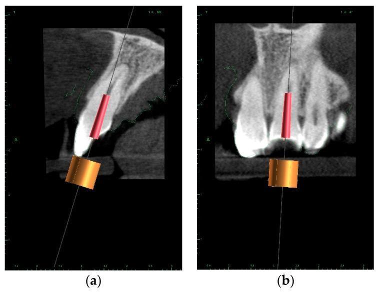
This diagnostic image displays a Cone Beam Computed Tomography (CBCT) scan used for guided endodontic planning, shown in (a) sagittal and (b) coronal cross-sections. The visual demonstrates the digital mapping of a virtual implant (red cylinder) within a maxillary tooth, representing the path for a planned access drill. A thin, continuous vertical line indicates the intended access trajectory from the occlusal/incisal surface toward the root canal system. An orange cylindrical guide sleeve is positioned externally to represent the teeth-supported surgical template. The educational focus is on 'Guided Endodontics' and the preservation of pericervical dentin, illustrated by the lighter shaded volume of tooth structure surrounding the planned drill path. This imaging modality is used to treat pulp canal calcification by accurately localizing obliterated canals while minimizing the risk of perforation. The content is intended for advanced dental students or endodontic specialists learning computer-aided design and manufacturing (CAD/CAM) workflows in clinical dentistry.
Guided Endodontics
Definition
Rationale / Need for Guided Endodontics
- The root canal space is narrowed or entirely obliterated
- Standard access preparation risks perforation
- Even experienced clinicians under magnification may fail to locate the canal
Types of Guided Endodontics
1. Static Guided Endodontics (SGE)
2. Dynamic Guided Endodontics (DGE)
Workflow / Steps
Step 1: Data Acquisition
- Take a CBCT scan of the region (DICOM data)
- Take an intraoral surface scan or conventional impression of the arch (STL file)
- These two datasets are merged in planning software
Step 2: Virtual Treatment Planning
- Import CBCT + intraoral scan data into planning software (e.g., coDiagnostiX, implant planning software)
- Virtually place a thin drill (1.0 mm or less) along the planned canal path
- Define:
- Target point - assumed location of pulp space (identified by periapical pathology even if canal not visible)
- Entry point - on the incisal/occlusal surface where drilling begins
- Drill path angle in all three dimensions
- Drill diameter - typically 0.5-1.0 mm
Step 3: Guide Fabrication
- The template geometry is exported as an STL file
- The guide is fabricated by 3D printing or CAD/CAM milling
- A titanium or metal drill sleeve is embedded in the guide to control direction and depth
- The guide is teeth-supported (rests on adjacent teeth for stability)
Step 4: Intraoperative Use
- Try-in the guide on the dental arch; check stability
- Use a marking pin dipped in blue stain to mark the exact entry point on the tooth
- Remove the guide; prepare the enamel at the marked point
- Re-seat the guide and drill through the sleeve using a long-necked, small-diameter drill at controlled depth
- Remove the guide; access the located canal with standard endodontic instruments
Step 5: Conventional Endodontic Completion
- Once the canal is located, proceed with standard RCT (shaping, cleaning, obturation)
Digital Workflow Illustration
Indications
- Pulp Canal Calcification (PCC) - primary indication
- Teeth with no visible canal on radiograph or CBCT but with periapical pathology (sign of remaining pulp tissue)
- Minimally invasive endodontic access (conservative cavity design)
- Selective root re-treatments where original canal orifice is obliterated by post or restorative material
- Dens invaginatus and other complex anatomical variants
- Guided endodontic surgery (osteotomy + root-end resection)
Advantages
| Advantage | Detail |
|---|---|
| Precision | Highly accurate - guided path matches planned path to within ~0.5 mm |
| Safety | Reduces risk of perforation in calcified teeth |
| Minimally invasive | Preserves more pericervical dentin compared to exploratory access |
| Reproducibility | Less operator-dependent; even less experienced clinicians achieve good results |
| Success | Higher canal location rates in PCC teeth vs freehand |
Limitations
- Only works for straight segments of root canals - curved canals cannot be drilled in a curved path through a rigid guide
- The tooth must remain fixed in position during both CBCT and drilling - any movement causes inaccuracy
- Metallic restorations create CBCT scatter artifacts, reducing planning accuracy
- Limited interocclusal distance in posterior teeth may not allow the long-necked drill and handpiece to be placed through the guide
- Static guides cannot be changed intraoperatively if anatomy differs from the plan
- Cost and availability - requires CBCT, intraoral scanner, planning software, 3D printer/milling, and special drills/sleeves
- Learning curve - adequate training required for planning software
- Planning time - not suitable for emergency scenarios
Accuracy
- Guided access preparation is highly accurate compared to freehand technique
- Mean deviation between planned and actual drill path: approximately 0.3-0.7 mm at the tip
- A 2025 clinical trial (PMC) showed higher canal location success in static guided group vs freehand specialist group for teeth with average calcification depth of 11-12 mm
Guided Endodontic Surgery
- First described by Giacomino et al. (2018)
- A 3D-printed guide is used for combined osteotomy + root-end resection using a trephine bur
- The guide controls depth and angulation of the osteotomy
- Applicable in cases where the surgical site is near vital structures
Conclusion
Root canal sealers 10marks pdf
root canal sealers classification types properties 10 marks endodontics
https://www.ncbi.nlm.nih.gov/books/NBK587367
root canal sealers types classification endodontic obturation
https://pmc.ncbi.nlm.nih.gov/articles/PMC12471766
Root Canal Sealers
Definition
"A radiopaque dental cement used, usually in combination with a solid or semi-solid core material, to fill voids and to seal root canals during obturation."
Need for Root Canal Sealers
- Gutta-percha alone cannot seal the canal perfectly due to surface irregularities
- Sealers fill the void between gutta-percha and canal walls
- They penetrate dentinal tubules and lateral canals
- They act as a lubricant for gutta-percha insertion
- They provide antibacterial activity
Ideal Properties of Root Canal Sealers
| Property | Description |
|---|---|
| Sticky/Tacky | Provide good adhesion to canal walls and core material when set |
| Hermetic seal | Produce a fluid-tight seal |
| Radiopaque | Distinguishable on radiographs |
| Fine particle size | For thin film thickness and anatomical accommodation |
| Dimensional stability | No shrinkage on setting |
| Insoluble | Insoluble in tissue fluids after setting |
| Non-irritant | Biocompatible; non-toxic to periapical tissues |
| Bacteriostatic | Inhibit bacterial growth |
| Slow setting | Allow adequate working time |
| Non-staining | Should not discolour tooth structure |
| Soluble | Soluble in common solvents for retreatment |
| Non-mutagenic/non-carcinogenic | No systemic adverse effects |
Classification of Root Canal Sealers
Based on Composition (Most commonly used classification):
- Zinc Oxide-Eugenol (ZOE) based sealers
- Calcium hydroxide-based sealers
- Resin-based sealers (Epoxy resin / Methacrylate resin)
- Glass ionomer-based sealers
- Bioceramic/Calcium silicate-based sealers
- MTA-based sealers
- Silicone-based sealers
- Medicated sealers (containing antibiotics/paraformaldehyde)
Detailed Description of Each Type
1. Zinc Oxide-Eugenol (ZOE) Based Sealers
- Powder: Zinc oxide, staybelite resin, bismuth subcarbonate (radiopacity), barium sulphate, sodium borate
- Liquid: Eugenol
- Good antimicrobial and anti-inflammatory properties (eugenol)
- Absorbed by tissues if extruded
- Available as powder-liquid or 2-paste system
- Become weak and porous on setting
- Susceptible to decomposition by tissue fluids
- Eugenol is cytotoxic in vitro (though clinically acceptable)
- Shrinkage on setting
- Solubility in tissue fluids
2. Calcium Hydroxide-Based Sealers
- Strong alkalinity (pH ~12.5) - antibacterial, neutralises endotoxins
- Promotes periapical healing
- Stimulates hard tissue formation (calcific bridge)
- Good biocompatibility
- Osteogenic and cementogenic potential
- Useful in teeth with extensive periapical lesions
- High long-term solubility (calcium hydroxide dissolves over time)
- Poor sealing ability compared to resin sealers
- Calcium hydroxide gradually resorbs, potentially creating voids
3. Resin-Based Sealers
a) Epoxy Resin-Based
- Paste A: Bisphenol A diglycidyl ether resin, zirconium oxide, iron oxide pigments
- Paste B: Amines (hardener), calcium tungstate, silicone oil
- Excellent adhesion to dentinal walls (bonds covalently to collagen)
- Low solubility and low shrinkage
- Good long-term sealing ability
- Long working time
- AH 26 releases formaldehyde initially (cytotoxic) - AH Plus does not
- Initial inflammatory reaction in periapical tissues
- Potential for allergic and mutagenic reactions
- Difficult to remove during retreatment
b) Methacrylate Resin-Based
- Classified into 4 generations based on primer type and etching mechanism
- Self-adhesive variants available
- Create potential "monoblock" within the canal
4. Glass Ionomer-Based Sealers
- Chemical bonding to dentin (fluoride release)
- Dimensional stability
- Antibacterial due to fluoride release
- Biocompatible
- Brittle - fractures under stress
- Poor flow into lateral canals
- Difficult to remove during retreatment
5. Bioceramic / Calcium Silicate-Based Sealers
- Excellent biocompatibility and bioactivity
- Does not shrink on setting
- Hydrophilic (performs well in moist environments)
- Releases calcium and hydroxyl ions - stimulates periapical healing and tissue regeneration
- Osteogenic and cementogenic potential
- Excellent sealing ability
- Shorter setting time than MTA
- Difficult retreatment (extremely strong bond to dentin)
- More expensive
- Limited long-term clinical data
6. MTA-Based Sealers
- Calcium silicate-based (related to bioceramic sealers)
- Promotes fibroblast and osteoblast adhesion
- Mild antibacterial (calcium ion release, elevated pH)
- Better biocompatibility than traditional resin sealers
- Lower cytotoxicity
- Extended setting time
- Difficult handling characteristics
- Less clinical flexibility than newer bioceramics
7. Silicone-Based Sealers
- Well tolerated by tissues
- Very low water sorption
- Slight expansion on setting (improves seal)
- Forms monoblock with canal walls (potential canal reinforcement)
- Good flow into lateral canals
- GuttaFlow can be used as sealer and core material combined
8. Medicated Sealers (Paraformaldehyde-containing)
- Antimicrobial
- Contains paraformaldehyde (tissue fixative) and corticosteroid
- Reduces postoperative pain initially
- Highly toxic to periapical tissues and bone
- Paraformaldehyde is mutagenic/carcinogenic
- Use is controversial and largely discouraged/banned in many countries
- Can cause paresthesia if extruded
Comparison Table
| Property | ZOE | Ca(OH)₂ | Epoxy Resin | Bioceramic |
|---|---|---|---|---|
| Adhesion to dentin | Moderate | Poor | Excellent | Excellent |
| Solubility | Moderate | High | Very Low | Low |
| Biocompatibility | Moderate | Good | Moderate | Excellent |
| Antimicrobial | Good | Good | Moderate | Good |
| Tissue regeneration | No | Yes | No | Yes |
| Retreatability | Easy | Moderate | Difficult | Very difficult |
| Setting shrinkage | Yes | Yes | Minimal | No (slight expansion) |
| Clinical use | Widely used | Common | Gold standard | Increasing |
Methods of Sealer Application
- Lentulo spiral - most common; rotary placement in canal
- Master cone tip - sealer coated on gutta-percha tip
- Sonic/ultrasonic application - improves flow into dentinal tubules
- Paper point dipped in sealer
- Syringe delivery (bioceramic sealers)
Causes of Sealer Failure
- Shrinkage on setting - creates voids
- High solubility - sealer dissolves, leaving gaps
- Poor adhesion to dentin or gutta-percha
- Improper thickness of sealer layer (too thick or too thin)
- Contamination with blood or tissue fluid
Recent Advances in Sealers
- Antibiotic-incorporated sealers - CHX, nanosilver, ciprofloxacin added for enhanced antimicrobial activity against E. faecalis
- Nanoparticle-enhanced sealers - improved sealing and antibacterial properties
- Smart/stimuli-responsive sealers - under research
- Single-cone bioceramic obturation - bioceramic sealer + single matched gutta-percha cone (simplified technique)
Conclusion
- For routine cases: AH Plus (epoxy resin) remains the gold standard for long-term sealing
- For biological/regenerative potential: Bioceramic sealers (iRoot SP, BC Sealer) are the preferred modern choice
- For cases requiring retreatability: ZOE or Ca(OH)₂-based sealers are preferred
- Medicated (paraformaldehyde) sealers should be avoided due to tissue toxicity