
Steps of bipolar hemiarthroplaty via lateral approach
bipolar hemiarthroplasty lateral approach hip surgical steps
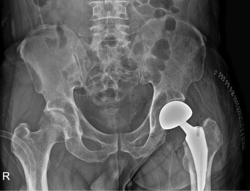
Anteroposterior (AP) radiograph of the pelvis and proximal femurs showing a left-sided hip bipolar hemiarthroplasty. The orthopedic implant consists of a radiopaque femoral stem securely fixed within the proximal femoral canal and a large, spherical prosthetic head articulating with the native acetabulum. The right hip joint appears intact and anatomically normal, providing a comparative reference. The pelvic ring, including the ilium, ischium, and pubis, is clearly visualized, along with the sacrum and lumbar vertebrae. Surgical skin staples are visible on the lateral aspect of the left thigh, indicating the recent operative approach. This diagnostic image is used to assess postoperative implant positioning, limb length alignment, and the absence of acute complications such as fracture or immediate dislocation. The visualization of the prosthetic head’s circular profile is a key clinical sign for confirming proper component orientation.
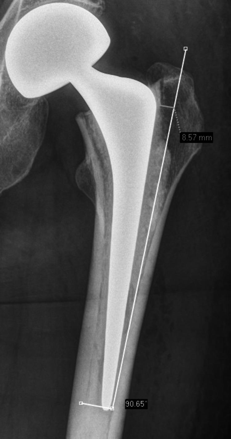
Anterior-posterior (AP) diagnostic X-ray of a proximal femur showing a bipolar hip hemiarthroplasty implant in situ. The image highlights the surgical assessment of the lateral femoral wall (greater trochanter) preparation. A longitudinal white reference line is drawn parallel to the femoral shaft axis along the medial border of the lateral femoral cortex. A horizontal measurement of 8.57 mm is indicated between this reference line and the lateral edge of the proximal femoral bone, demonstrating the thickness of the lateral wall that was not resected during stem preparation. At the distal end of the femoral stem, an angular measurement of 90.65 degrees is shown relative to the femoral axis to assess stem alignment. The radiopaque implant features a bipolar prosthetic head articulating with the native acetabulum and a medullary stem. The image serves as an educational tool for orthopedic surgery, specifically focusing on prosthetic fitting, rasping techniques, and the radiological evaluation of hemiarthroplasty component positioning relative to anatomical landmarks.
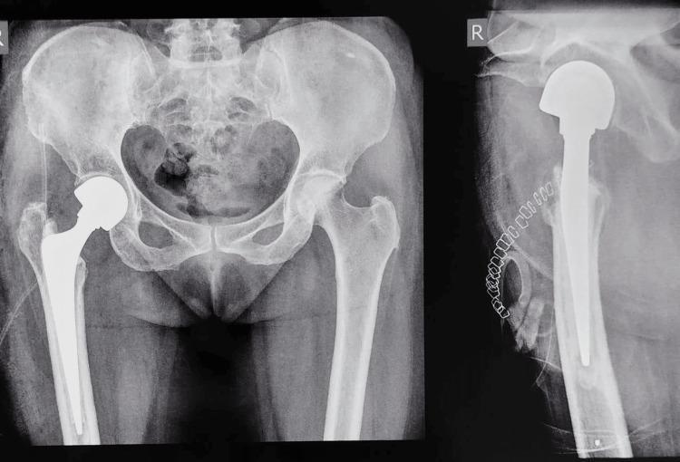
This diagnostic imaging set consists of postoperative anteroposterior (AP) and lateral X-ray views of the pelvis and right hip, demonstrating a right-sided cemented bipolar hemiarthroplasty. The prosthesis includes a metallic femoral stem securely positioned within the intramedullary canal of the proximal femur, a modular neck, and a large spherical bipolar femoral head articulating with the native acetabulum. A radio-opaque cement mantle is visible surrounding the femoral stem, ensuring fixation, and a small radio-opaque cement restrictor is identified distal to the stem tip on the lateral view. Surgical skin staples are visible along the lateral soft tissues. The contralateral left hip joint remains intact with no evidence of arthropathy. The pelvic ring, including the ilium, ischium, and pubis, shows normal alignment. This image serves as a teaching example for orthopedic oncology management, specifically the surgical reconstruction of a pathological femoral neck fracture secondary to metastatic disease using bone cement for both fixation and local tumor control.
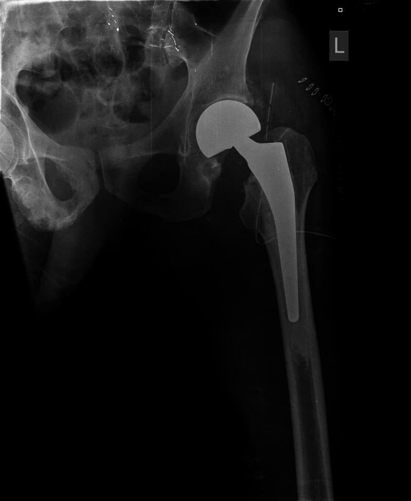
This diagnostic image is an anteroposterior (AP) radiograph of the left hip demonstrating a post-surgical cemented bipolar hemiarthroplasty. The orthopedic implant consists of a radio-opaque femoral stem well-seated within the intramedullary canal of the proximal femur, and a large-diameter bipolar femoral head articulating with the native acetabulum. There is evidence of bone cement appearing as a radiodense interface between the stem and the femoral cortex. Visible surgical markers include small, radio-opaque hemostatic clips in the periacetabular soft tissues and linear radiopaque sutures or markers along the lateral aspect of the hip joint. The radiograph confirms appropriate postoperative alignment of the prosthetic components relative to the pelvic and femoral anatomy. This visual serves as an educational example of hip arthroplasty for femoral neck fractures, highlighting implant positioning and common postoperative radiographic findings in orthopedic surgery.
Bipolar Hemiarthroplasty via Lateral Approach
Indications
- Displaced femoral neck fracture (Garden III/IV) in the elderly
- Pathological fracture of the femoral neck
- Failed internal fixation of femoral neck fracture
Patient Positioning
Step-by-Step Technique
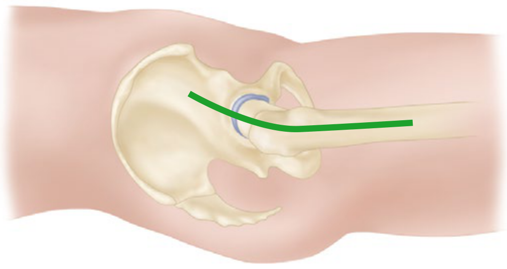
Step 1 - Skin Incision
- Make a straight lateral incision centered over the tip of the greater trochanter, extending approximately 10-15 cm - roughly 5 cm proximally and 10 cm distally along the line of the femoral shaft.
- The incision is centered on the greater trochanter.
Step 2 - Fascia Lata and IT Band
- Divide the iliotibial band (fascia lata) in line with the skin incision.
- Expose the greater trochanter and the musculature overlying it.
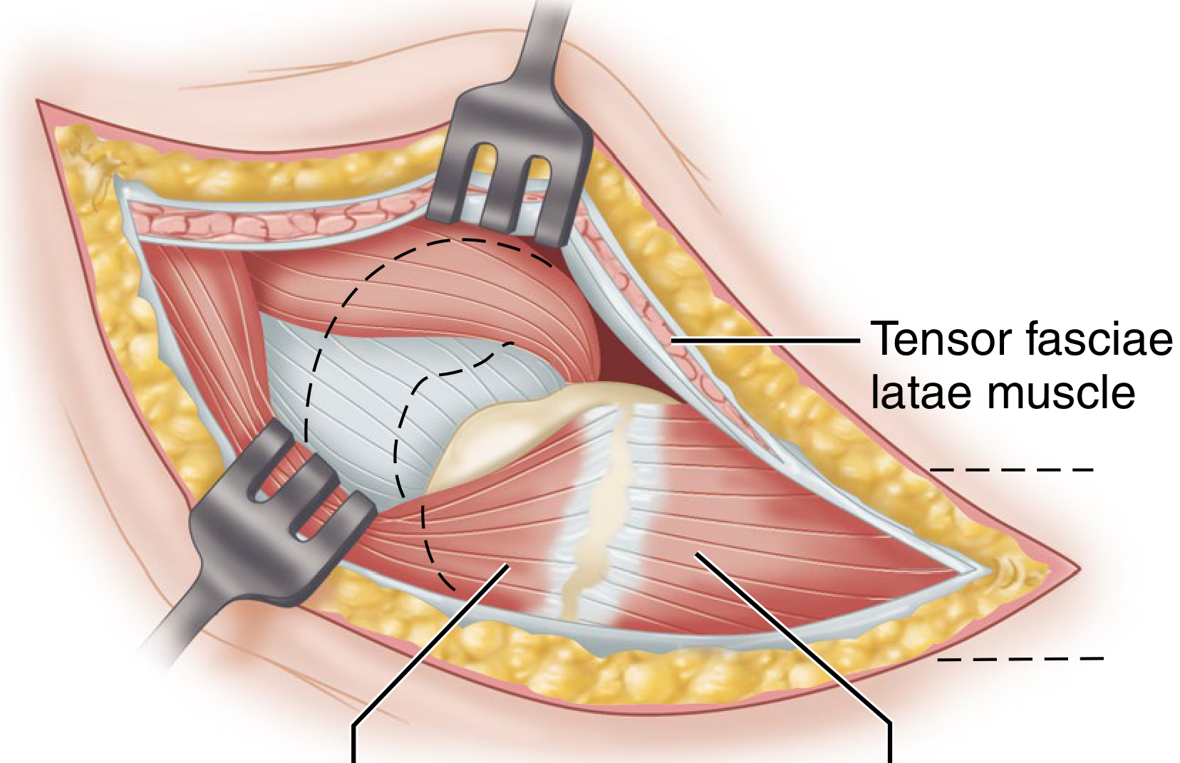
Step 3 - Gluteus Medius / Abductor Sleeve (Hardinge Release)
- Release the anterior one-third of the gluteus medius, the underlying gluteus minimus, the abductor tendon, and the vastus lateralis distally - all in a continuous sleeve off the greater trochanter.
- This is done in an anterior-to-posterior direction, keeping the release to the anterior third only to avoid denervating the posterior abductors.
- Critical landmark: The superior gluteal nerve runs approximately 5 cm proximal to the tip of the greater trochanter. Dissection must not extend more than 3-4 cm proximal to the trochanteric tip to protect this nerve - injury causes permanent abductor weakness and Trendelenburg gait.
Step 4 - Capsulotomy
- Retract the abductor sleeve anteriorly.
- Incise the hip joint capsule longitudinally along the anterosuperior surface of the femoral neck.
- Place retractors around the femoral neck to expose the fracture site.
- The origin of the vastus lateralis may be reflected distally or split longitudinally to expose the base of the trochanter and proximal femoral shaft.
Step 5 - Femoral Head Dislocation and Removal
- With the hip in flexion, adduction, and external rotation, lever the femoral head out of the acetabulum.
- Use a corkscrew device inserted into the femoral head to assist extraction.
- Remove the femoral head and measure its diameter - this determines prosthetic head sizing.
Step 6 - Femoral Neck Osteotomy
- If the fracture plane has not already defined the cut, perform a femoral neck osteotomy at the appropriate level (typically 1-1.5 cm above the lesser trochanter, at a 135-140° angle).
- Use the template or the excised femoral head as a guide to plan the cut level and version.
- Remove all fragments of the femoral head and neck from the acetabulum.
Step 7 - Acetabular Assessment
- Inspect the acetabular cartilage. In hemiarthroplasty, the acetabulum is not replaced - it must have intact cartilage to articulate with the bipolar prosthesis.
- Remove any osteophytes or debris. Confirm the labrum is intact.
Step 8 - Femoral Canal Preparation
- Open the femoral canal at the piriform fossa using a box chisel or awl.
- Broach sequentially in increasing sizes, maintaining neutral anteversion (approximately 10-15°). Each broach should be seated in the same version and alignment before proceeding to the next size.
- Avoid varus malpositioning (a common error with the lateral approach).
- Once the broach fits firmly (cortical chatter, no further advancement with mallet), select the final stem size.
- For cemented fixation: use a cement restrictor, lavage and dry the canal, pressurize bone cement, and insert the stem in correct version. Hold until cement sets.
- For uncemented (press-fit) fixation: impaction of the final stem directly.
Step 9 - Trial Reduction and Head Sizing
- Attach a trial femoral head (matching the excised head diameter - typically 40-54 mm for bipolar).
- Reduce the hip and assess:
- Stability through a range of motion (flexion, internal rotation, adduction)
- Leg length - use intraoperative landmarks (lesser trochanter level, longitudinal tension)
- Offset - adequate soft tissue tension without impingement
- The bipolar head consists of an inner bearing (metal head articulating with a polyethylene-lined outer cup) that then articulates with the native acetabulum - providing two points of motion and reducing acetabular erosion compared to a unipolar prosthesis.
Step 10 - Final Component Assembly and Reduction
- Once satisfied with trial, remove the trial and attach the definitive femoral head and assemble the bipolar cup.
- Reduce the hip under direct vision. Confirm stability, leg length, and range of motion.
Step 11 - Wound Closure
- Repair the abductor sleeve (gluteus medius / minimus and vastus lateralis) firmly back to the greater trochanter using strong non-absorbable sutures (e.g., No. 5 Ethibond) through bone tunnels or transosseous sutures. This is the most important step for restoring abductor function.
- Close the iliotibial band.
- Close subcutaneous tissue and skin in layers.
- Insert a drain if desired.
Key Advantages of the Lateral Approach for Hemiarthroplasty
| Feature | Lateral Approach |
|---|---|
| Dislocation rate | Very low (0.55%) |
| Nerve at risk | Superior gluteal nerve |
| Internervous plane | No (muscle splitting) |
| Position | Lateral decubitus or supine |
| Abductor repair | Required - critical step |
| Risk | Trendelenburg gait if superior gluteal nerve or abductor repair compromised |
Postoperative Care
- Weight bearing as tolerated from day 1 (most cases)
- Hip precautions are less restrictive than posterior approach (no posterior dislocation precautions needed)
- Abductor strengthening physiotherapy
- DVT prophylaxis