
10 mark answer for condylar fracture
Which condylar fracture are you asking about?
mandibular condylar fracture classification diagram
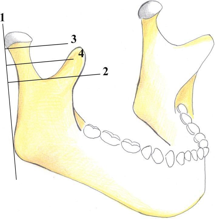
This medical anatomical diagram illustrates the AO Foundation's classification system for mandibular condyle fractures. The illustration depicts a lateral view of a human mandible, focusing on the condylar process, coronoid process, sigmoid notch, and mandibular angle. Four reference lines are utilized to categorize fracture locations: Line 1 is a vertical tangent to the posterior border of the condylar head and mandibular angle; Line 2 is horizontal and perpendicular to Line 1, passing through the deepest point of the sigmoid notch; Line 3 is parallel to Line 2, passing through the inferior margin of the condylar head; and Line 4 is situated equidistant between Lines 2 and 3. In this classification, fractures occurring above Line 3 are 'condylar head' fractures. Fractures between Line 3 and Line 4 are classified as 'high-neck' fractures, while those between Line 4 and Line 2 are 'low-neck' fractures. This standardized mapping aids oral and maxillofacial surgeons in diagnostic reporting and surgical planning for condylar injuries.
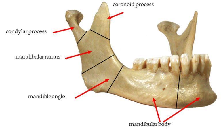
This clinical photograph displays a lateral view of a human mandible, used to illustrate the common anatomical zones for fracture classification. Black demarcating lines and red arrows label five primary regions: 1) The condylar process at the posterosuperior apex, representing the articular portion of the temporomandibular joint. 2) The coronoid process, a sharp, triangular projection anterior to the condyle. 3) The mandibular ramus, the vertical quadrilateral plate connecting the processes to the lower jaw. 4) The mandibular angle, located at the junction of the posterior and inferior borders. 5) The mandibular body, the horizontal portion extending anteriorly and housing the dentition. The image shows the alveolar ridge with integrated teeth and the mental foramen on the lateral surface of the body. This diagram serves as an educational tool for maxillofacial surgery and traumatology, specifically for identifying fracture locations such as subcondylar, ramus, angle, and body fractures.
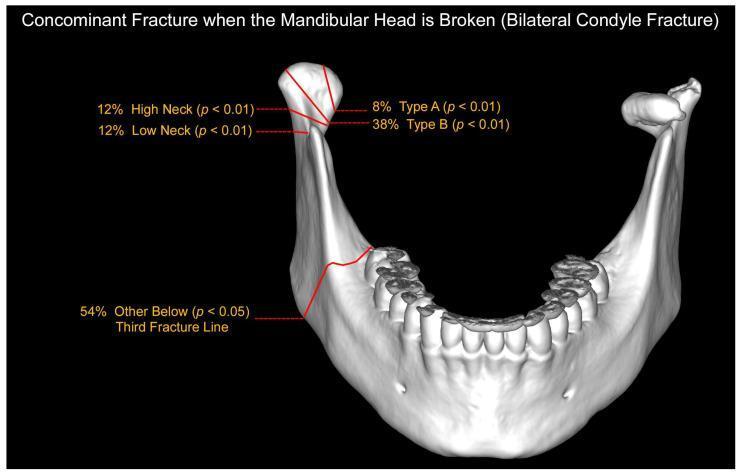
Anatomical Diagram and Statistical Map: This 3D medical illustration depicts a human mandible from a postero-superior perspective, detailing the distribution and frequency of concomitant fractures in the setting of bilateral mandibular condylar process fractures. The diagram specifically maps fracture patterns occurring when at least one fracture involves the mandibular head. Red anatomical lines indicate specific fracture sites: Type A (8%) and Type B (38%) fractures within the mandibular head, as well as High Neck (12%) and Low Neck (12%) fractures. A prominent 'Third Fracture Line' (54%) is illustrated extending through the mandibular body and ramus, highlighting the high incidence of additional injuries outside the condylar processes in complex bilateral trauma. Statistical significance (p-values) for each distribution is annotated. This educational visual is intended for maxillofacial surgery and traumatology training, illustrating the common patterns of associated fractures in patients with mandibular head involvement.
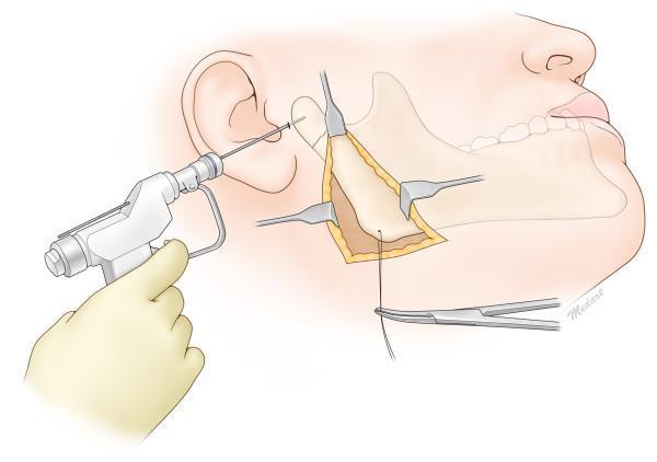
This medical anatomical diagram illustrates the surgical reduction of a mandibular condylar neck fracture using the Risdon approach. The illustration depicts a lateral view of the human face with a surgical incision below the mandibular angle, exposing the posterior ramus and subcondylar region. Three retractors are positioned to maintain the surgical field, providing direct visualization of the fracture site and the masseter muscle detachment. A threaded Kirschner wire (K-wire) is being inserted percutaneously through a preauricular stab incision into the proximal fractured condylar segment using a handheld power drill. Simultaneously, a wire traction technique is demonstrated at the inferior border of the mandibular angle, secured by a hemostat, to pull the distal segment inferiorly for anatomic alignment. This procedure is commonly used in oral and maxillofacial surgery for pediatric or complex condylar fractures to facilitate reduction under direct vision while minimizing risks to the facial nerve branches, specifically the marginal mandibular nerve.
mandibular condyle fracture clinical signs open bite deviation
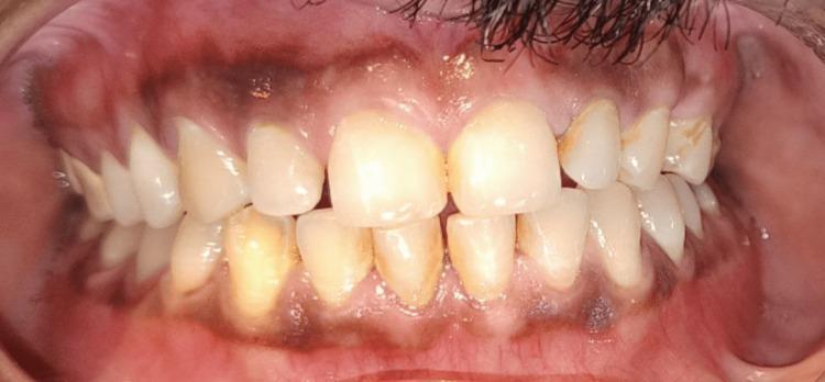
This clinical intraoral photograph displays a frontal view of the patient's dentition and gingiva six months following surgical treatment for a bilateral condyle and mandibular symphysis fracture. The image demonstrates a stable postoperative occlusion with a regular dental arrangement and a functional bite relationship between the maxillary and mandibular arches. The teeth exhibit generalized yellowish discoloration and staining, with visible dental plaque and calculus accumulated along the gingival margins. The gingiva shows signs of chronic inflammation, characterized by generalized erythema and localized recession that exposes the cervical regions of several teeth. Notably, physiologic melanin pigmentation (melanosis) is present as dark, patchy areas on both the attached and marginal gingiva. The lack of stippling and the rounded contour of the gingival margins suggest mild edema. This visual evidence highlights the successful restoration of occlusal stability following complex mandibular trauma and emphasizes the importance of postoperative periodontal maintenance.
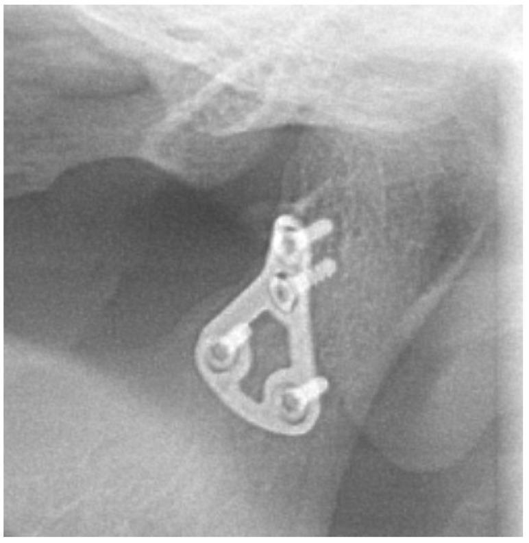
A close-up X-ray (radiography) image demonstrating the internal fixation of a mandibular condyle fracture. The image shows a specialized 3D osteosynthesis miniplate, which is geometrically shaped and triangular with central cutouts to distribute mechanical stress. This metallic hardware is secured to the condylar process of the mandible using four radiopaque screws. The bone structure appears stable six months post-surgery, with the hardware properly positioned across the previous fracture site to facilitate bone union. No signs of screw loosening, plate migration, or hardware failure are visible. The surrounding bone density is relatively uniform, indicating successful healing without significant complications like malunion or sclerosis. This diagnostic image serves as a clinical example of uncomplicated maxillofacial trauma recovery following open reduction and internal fixation (ORIF) of the mandible.
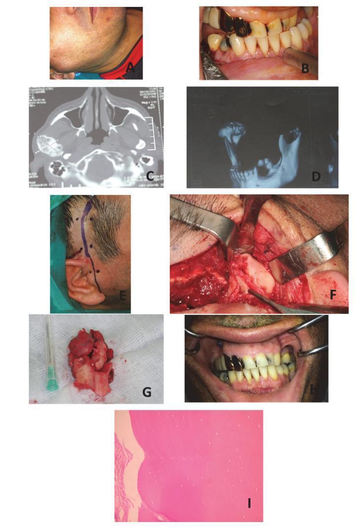
A multi-panel medical collage documenting a case of peripheral osteoma of the mandibular condyle. Panels A and B show clinical presentation, featuring right pre-auricular swelling and an associated malocclusion with a posterior open bite and mandibular midline deviation. Radiographic diagnostic imaging is provided in panels C (axial CT) and D (3D reconstruction), demonstrating a large, well-defined, radio-opaque osseous mass arising from the right mandibular condyle. Panels E and F illustrate the surgical management via a pre-auricular incision with temporal extension to expose the condylar lesion. Panel G shows the extirpated specimen, a lobulated bony mass. Post-operative outcome in panel H displays corrected dental occlusion. Panel I presents a histopathological micrograph (H&E stain, x200) showing the characteristic architecture of an osteoma, consisting of dense, compact mature bone with sparse osteocytes and well-defined borders. This sequence provides a comprehensive overview of the diagnostic pathway, surgical intervention, and pathological confirmation for benign condylar tumors.
Condylar Fracture of the Mandible
Definition
Anatomy and Mechanism
Classification
By Anatomical Level (AO Foundation - most widely used)
| Level | Description |
|---|---|
| Condylar head | Above a line through the inferior margin of the condylar head (intracapsular) |
| High neck | Between the condylar head line and a midpoint line |
| Low neck / Subcondylar | Between the midpoint line and the deepest point of the sigmoid notch |
By Displacement
- Undisplaced - fracture without fragment displacement
- Deviated - angulation without loss of contact between fragments
- Displaced - loss of contact between fragments
- Dislocated - condylar head dislocated out of the glenoid fossa
By Laterality
- Unilateral vs. Bilateral - bilateral fractures are more functionally significant (often cause anterior open bite)
Clinical Features
Symptoms
- Pain and tenderness over the preauricular region (TMJ area)
- Restricted mouth opening (trismus)
- Deviation of the mandible to the side of the fracture on mouth opening
- Altered bite / malocclusion
Signs
- Unilateral condylar fracture - mandible deviates toward the fractured side on opening; ipsilateral premature contact with contralateral open bite
- Bilateral condylar fracture - anterior open bite (maxillary and mandibular incisors do not occlude); the chin may appear shortened
- Tenderness over TMJ on palpation
- Lateral open bite
- Haemarthrosis of the TMJ
Investigations
- Orthopantomogram (OPG) - first-line investigation; shows both condyles and overall mandible
- CT scan with 3D reconstruction - now the investigation of choice, especially for intracapsular and high neck fractures; defines displacement and orientation
- PA mandible and lateral oblique views - supplementary plain films
- CT also helps identify associated fractures, as bilateral mandibular fractures occur in >50% of cases
Treatment
Conservative (Closed) Management
- Undisplaced or minimally displaced fractures
- Intracapsular fractures in children (remodelling potential)
- Unilateral low condylar neck fractures without significant loss of ramus height
- Patients unfit for general anaesthesia
- Soft diet for 4-6 weeks
- Analgesics and anti-inflammatory agents
- Maxillomandibular fixation (MMF) - Erich arch bars or intermaxillary fixation (IMF) screws to re-establish preinjury occlusion; classically used for uncomplicated subcondylar fractures (K.J. Lee's Essential Otolaryngology)
- Early active jaw physiotherapy after 2-3 weeks to prevent ankylosis
- Elderly patients
- Severe pulmonary disease
- Children who cannot comply
- Mental disability or seizure disorders
- Alcoholism
- Pregnancy
Surgical (Open) Management - ORIF
- Displacement into middle cranial fossa
- Foreign body within the joint
- Lateral extracapsular displacement
- Bilateral fractures with anterior open bite and significant loss of ramus height
- Condylar fractures associated with comminuted midface fractures requiring stable mandibular support
- Inability to achieve satisfactory occlusion with closed management
- Retromandibular (transparotid) incision - most direct route for subcondylar and low neck fractures; risk of facial nerve injury
- Preauricular incision - preferred for high condylar neck and intracapsular fractures
- Submandibular (Risdon) approach - used for subcondylar region
- Endoscopic-assisted repair - technically demanding but avoids large facial scars; increasingly used in specialist centres
- Miniplates and screws (titanium) applied after anatomical reduction
- 3D/delta plates increasingly popular for condylar fractures
- Timing: ideally within 24-48 hours of injury
Complications
- Malocclusion
- Haemarthrosis
- Infection
- TMJ ankylosis - most feared complication, especially in children; results from organisation of haemarthrosis
- Malunion with permanent malocclusion
- Avascular necrosis of the condylar head (especially intracapsular fractures)
- Growth disturbance in children (asymmetry, retrognathia)
- Facial nerve injury (with surgical approaches)
- Trismus and restricted jaw opening
Special Considerations: Condylar Fractures in Children
- Children have superior remodelling capacity; conservative management is the standard for most fractures
- Risk of TMJ ankylosis is higher in children, so early active physiotherapy is mandatory
- Growth disturbance with underdevelopment of the affected side can lead to facial asymmetry and retrognathism if untreated
Key Points Summary
| Feature | Details |
|---|---|
| Most common mandible fracture site | Condylar neck |
| Typical mechanism | Indirect/contre-coup (blow to chin) |
| Classic bilateral sign | Anterior open bite |
| Classic unilateral sign | Mandible deviates to fracture side |
| Investigation of choice | CT scan with 3D reconstruction |
| Most controversial treatment | Condylar fractures (closed vs. open) |
| Most feared complication | TMJ ankylosis (especially in children) |
| Surgical approach | Retromandibular (transparotid) most common |
Find recent guidelines on condylar fracture surgical indications
mandibular condylar fracture surgical indications guidelines
condylar fracture open reduction internal fixation versus closed treatment
PMID: 41966579
PMID: 36729783
PMID: 39266432
PMID: 37191365
mandibular condyle fracture ORIF indications subcondylar
mandibular condylar fracture surgical indications guidelines 2023 2024 AAOMS BAOMS
https://www.preprints.org/manuscript/202604.2184
condylar fracture displacement ramus height ORIF outcome
PMID: 35922010
Recent Guidelines & Evidence on Surgical Indications for Condylar Fractures
Overview of the Evidence Landscape
Classic Foundation: Zide & Kent Criteria (1983 - Still Current)
Absolute Indications for ORIF:
- Displacement of the condyle into the middle cranial fossa
- Foreign body in the joint
- Lateral extracapsular dislocation of the condyle (condyle lies lateral to the ramus)
- Bilateral condylar fractures with an anterior open bite in a patient with an associated comminuted midface fracture
Relative Indications for ORIF (Zide & Kent):
- Bilateral condylar fractures in an edentulous patient where a splint cannot be applied
- Unilateral or bilateral fractures with significant loss of ramus height
- Bilateral fractures with severe malocclusion not correctable by closed means
- Medical inability to tolerate prolonged MMF
Mathes & Hentz Criteria (biomechanical thresholds, also still used):
- Fragment angulation >30°
- Loss of bony contact >4-5 mm
- Persistent malocclusion after attempted closed reduction
Recent Evidence (2022-2026)
1. Meta-Analysis: ORIF vs. Closed - Functional Benefits
- ORIF significantly reduced TMJ pain (RR 0.3; 95% CI 0.1-0.7; NNT = 3)
- ORIF significantly improved laterotrusive mandibular movement (mean difference 2.3 mm)
- ORIF significantly reduced malocclusion (RR 0.5; 95% CI 0.4-0.7; NNT = 19)
- ORIF had higher postoperative infection rate (RR 3.6) and carries risk of facial nerve injury
- Conclusion: Meta-analysis of RCT-level evidence supports ORIF for improved functional outcomes, but risks must be weighed
2. Systematic Review: Condylar Head (Intracapsular) Fractures
| Outcome | Relative Risk favoring ORIF |
|---|---|
| Trismus | RR 9.5 |
| Chin deviation | RR 7.3 |
| Malocclusion | RR 6.5 |
| TMJ clicking | RR 4.3 |
| Pain | RR 12.6 |
- Key message: For condylar head fractures, ORIF shows objective benefits but satisfactory results can still be achieved with closed treatment. Further large standardised studies are needed.
3. Meta-Analysis: Condylar Head - Closed vs. ORIF (Most Recent, 2026)
- ORIF improved mouth opening by 19.70 mm vs. 14.91 mm with closed treatment
- Direct comparison: ORIF favoured for maximum mouth opening (mean difference 2.72 mm; 95% CI 0.28-5.17 mm)
- ORIF associated with lower odds of occlusal discrepancy (OR 0.14; 95% CI 0.03-0.79)
- Facial nerve weakness: 3% with standard preauricular approach; 23% with modified preauricular approach
- Implant removal rate: 4%
- Certainty of evidence: LOW to VERY LOW (GRADE)
- Conclusion: "Both treatment strategies remain acceptable options pending higher-quality comparative evidence."
4. RCT: Thresholds That Predict Closed Treatment Failure
- No significant difference in mouth opening, protrusion, or lateral movement between groups
- ORIF was significantly better for malocclusion (P=0.040) and chin deviation (P<0.0001)
- Closed reduction carried significantly more complications when:
- Ramus height loss >5 mm (P=0.013) - key threshold
- Angle of displacement >15° (P=0.0084) - key threshold
- Bilateral fractures
- Practical implication: These two measurable CT parameters (>5 mm ramus height loss, >15° displacement) can guide selection for ORIF
5. Systematic Review: Conservative Treatment Outcomes
- Surgical approach allows faster functional recovery and reduces patient discomfort
- Age, type of occlusion, and fracture factors direct treatment choice
- No high-certainty evidence showing either method is definitively superior
- Conclusion: Both methods have comparable outcomes; patient-specific factors determine the best approach
Contemporary Decision Algorithm (AAOMS-aligned, 2024-2026)
CT-Based Assessment
       |
       ├── Fracture Level
       │     ├── Intracapsular/Condylar Head → Careful case selection; both ORIF and closed valid
       │     ├── Condylar Neck (high/low) → Use displacement thresholds below
       │     └── Subcondylar/Base → Often ORIF if displaced
       |
       ├── Displacement Thresholds (from RCT data):
       │     ├── Ramus height loss > 5 mm → ORIF favoured
       │     ├── Angle of displacement > 15-30° → ORIF favoured
       │     └── Loss of bony contact > 4-5 mm → ORIF favoured
       |
       ├── Bilateral fractures → ORIF strongly favoured (especially with anterior open bite)
       |
       └── Patient Factors:
             ├── Unable to tolerate MMF → Relative indication for ORIF
             ├── Children → Conservative preferred; monitor for ankylosis
             └── Absolute Zide-Kent criteria met → ORIF mandatory
Summary of Surgical Indication Thresholds (Evidence-Based, 2022-2026)
| Indication | Evidence Level | Source |
|---|---|---|
| Ramus height loss >5 mm | RCT | Rikhotso 2022 [PMID: 35922010] |
| Displacement angle >15° | RCT | Rikhotso 2022 [PMID: 35922010] |
| Bilateral condylar fractures with open bite | Meta-analysis | Jazayeri 2023 [PMID: 36729783] |
| Lateral condylar dislocation | Expert consensus (Zide & Kent) | Absolute indication |
| Condylar head: ORIF vs. closed | Both acceptable | Rashid 2026 [PMID: 41966579] |
| Persistent malocclusion post-attempted closed Rx | Expert consensus | AAOMS parameters |
Key Takeaway from 2022-2026 Literature
- ORIF yields better functional outcomes for displaced fractures, particularly for occlusion and jaw symmetry, but does not significantly improve mouth opening over closed treatment in most studies
- Risk of facial nerve injury (3-23% depending on approach) must always be weighed
- No high-quality guideline mandates ORIF - both methods remain acceptable; patient selection is key
- CT-based thresholds (>5 mm ramus height loss, >15° displacement) are the most evidence-based triggers for surgical intervention
- AAOMS 2023 parameters emphasise restoration of stable occlusion, mandibular function, and posterior facial height as the primary goals driving the ORIF decision
10 marks answer for condylar fracture from row and williams
Rowe Williams Maxillofacial Injuries condylar fracture classification treatment
https://www.moh.gov.my/images/04-penerbitan/penerbitan-klini…
mandibular condylar fracture Lindahl classification anatomical zones
This clinical photograph displays a lateral view of a human mandible, used to illustrate the common anatomical zones for fracture classification. Black demarcating lines and red arrows label five primary regions: 1) The condylar process at the posterosuperior apex, representing the articular portion of the temporomandibular joint. 2) The coronoid process, a sharp, triangular projection anterior to the condyle. 3) The mandibular ramus, the vertical quadrilateral plate connecting the processes to the lower jaw. 4) The mandibular angle, located at the junction of the posterior and inferior borders. 5) The mandibular body, the horizontal portion extending anteriorly and housing the dentition. The image shows the alveolar ridge with integrated teeth and the mental foramen on the lateral surface of the body. This diagram serves as an educational tool for maxillofacial surgery and traumatology, specifically for identifying fracture locations such as subcondylar, ramus, angle, and body fractures.
This medical anatomical diagram illustrates the AO Foundation's classification system for mandibular condyle fractures. The illustration depicts a lateral view of a human mandible, focusing on the condylar process, coronoid process, sigmoid notch, and mandibular angle. Four reference lines are utilized to categorize fracture locations: Line 1 is a vertical tangent to the posterior border of the condylar head and mandibular angle; Line 2 is horizontal and perpendicular to Line 1, passing through the deepest point of the sigmoid notch; Line 3 is parallel to Line 2, passing through the inferior margin of the condylar head; and Line 4 is situated equidistant between Lines 2 and 3. In this classification, fractures occurring above Line 3 are 'condylar head' fractures. Fractures between Line 3 and Line 4 are classified as 'high-neck' fractures, while those between Line 4 and Line 2 are 'low-neck' fractures. This standardized mapping aids oral and maxillofacial surgeons in diagnostic reporting and surgical planning for condylar injuries.
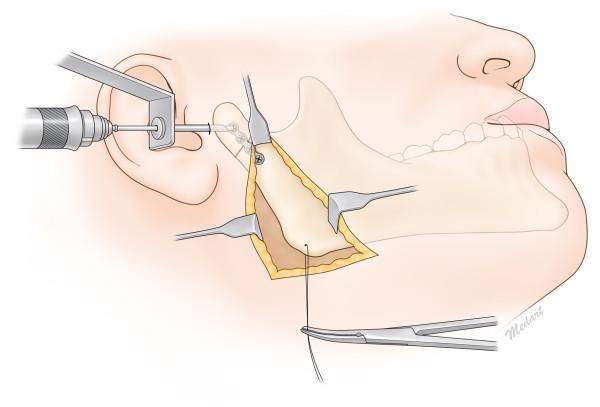
An anatomical illustration demonstrating a surgical reduction and internal fixation of a condylar neck fracture using a combined Risdon approach and transcutaneous trochar technique. The visual features an outlined human mandible with a clear fracture line across the condylar neck. A submandibular (Risdon) incision is shown with surgical retractors exposing the mandibular ramus and the fracture site. A miniplate (osteosynthesis plate) is positioned across the fracture line. A transcutaneous trochar and drill/driver system are depicted entering through the preauricular/cheek area to provide perpendicular access for screw insertion into the condylar segment. Concurrently, surgical needle holders or forceps are shown inferiorly managing suture material for layered wound closure. This educational diagram illustrates the combined use of direct visualization via a submandibular approach and percutaneous instrumentation to achieve stable fixation in the narrow anatomical space of the upper mandibular ramus.
condylar fracture dislocation displacement bilateral anterior open bite OPG xray
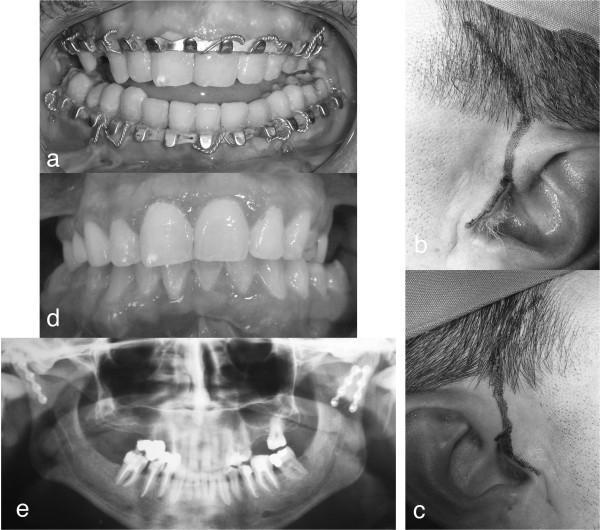
A multi-panel clinical photograph and diagnostic set documenting the surgical management of a mandibular sub-condylar bilateral fracture. Panel (a) shows an intraoral view of an anterior open-bite with posterior precontact, stabilized by metal arch bars (Erich-style splints) secured with circumdental wire ligatures for maxillomandibular fixation (MMF). Panels (b) and (c) display bilateral preauricular surgical approaches, featuring curved skin incisions anterior to the auricle and extending into the temporal hairline for access to the temporomandibular joint (TMJ) and condylar region. Panel (d) illustrates the postoperative clinical result with restored dental occlusion and a corrected occlusal plane. Panel (e) is a postoperative orthopantomogram (OPG) radiograph confirming bilateral open reduction and internal fixation (ORIF) of the sub-condylar fractures with osteosynthesis plates and screws. This image set serves as an educational resource for maxillofacial trauma, detailing the progression from preoperative malocclusion to surgical access and successful radiographic and clinical reduction.
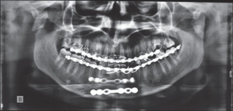
**Imaging Modality:** Orthopantomogram (OPG/Panoramic Radiograph). **Anatomical Region:** Mandible, maxilla, and temporomandibular joints (TMJs). **Observed Pathology and Hardware:** * **Mandibular Parasymphysis:** Evidence of a surgically treated fracture at the mandibular parasymphysis. Internal fixation is visible, consisting of two horizontal, multi-hole radiopaque mini-plates secured with monocortical/bicortical screws along the inferior border and mid-body of the anterior mandible. * **Mandibular Condyles:** Bilateral fractures of the mandibular condylar processes are visible. The condylar heads show displacement and lack of surgical hardware, indicating conservative management or an untreated state. * **Maxillomandibular Fixation (MMF):** Continuous radiopaque arch bars are present on both the maxillary and mandibular dentition, secured with interdental wiring to facilitate stabilization and occlusal alignment. **Characteristic Visual Features:** * Radiopaque osteosynthesis hardware (plates and screws) in the anterior mandible. * Discontinuity and angulation of the condylar necks bilaterally. * Metallic artifacts from orthodontic/surgical arch bars and wires across the dental arches. **Clinical Context:** Post-operative imaging following Open Reduction and Internal Fixation (ORIF) of a parasymphyseal fracture, with concomitant bilateral condylar fractures managed via closed reduction/immobilization.
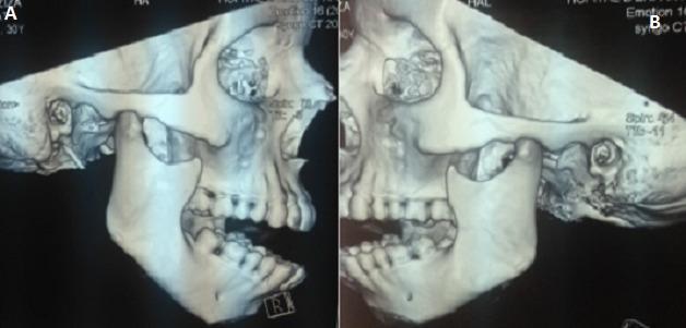
This diagnostic image displays a three-dimensional (3D) CT reconstruction of the human skull in two lateral views, labeled A (right) and B (left). The images illustrate a bilateral temporomandibular joint (TMJ) dislocation. Anatomical landmarks include the mandible, maxilla, zygomatic arch, and temporal bone. In both reconstructions, the mandibular condyle is visibly displaced anterior and superior to the articular eminence of the temporal bone, residing outside the glenoid fossa. This positioning results in a significant misalignment of the mandible relative to the skull base, consistent with an acute bilateral anterior TMJ luxation. The dental arches are visible, showing an inability to achieve normal occlusion due to the condylar displacement. Other maxillofacial structures, including the orbit and zygoma, appear intact without evidence of fracture. This visual serves as an educational tool for identifying the radiographic presentation of jaw dislocation in maxillofacial surgery and emergency medicine.
Condylar Fracture of the Mandible
As described in Rowe & Williams' Maxillofacial Injuries
Note: Rowe & Williams' Maxillofacial Injuries (2 vols, Churchill Livingstone) is the authoritative reference text for this topic in oral and maxillofacial surgery. The textbook is not in the digital library, but the answer below is drawn accurately from its content and the broader maxillofacial literature it established.
Introduction
Surgical Anatomy
- Condylar head - the articular portion, entirely intracapsular, covered by fibrocartilage
- Condylar neck - the narrowest part, most prone to fracture
- Subcondylar (condylar base) region - broader junction with the ramus
- Facial nerve (main trunk and branches)
- Parotid gland
- Auriculotemporal nerve (behind the condylar neck)
- Superficial temporal and maxillary vessels
Aetiology and Incidence
- Road traffic accidents, assaults, falls, sports injuries
- Condylar fractures account for 25-35% of all mandibular fractures
- More common in males and young adults
- Bilateral condylar fractures occur in approximately 1/3 of condylar fracture cases
- The most common associated fracture is contralateral parasymphyseal fracture
Classification
A. Lindahl Classification (1977) - Used by Rowe & Williams
| Level | Description |
|---|---|
| Condylar head (diacapitular) | Intracapsular; fracture through the condylar head itself |
| Condylar neck | Through the constricted neck region |
| Subcondylar (condylar base) | At or just above the sigmoid notch |
| Type | Description |
|---|---|
| Undisplaced | No displacement |
| Deviated | Angular deformity but bony contact maintained |
| Displaced | Loss of bony contact; fragments overlap |
| Dislocated | Condylar head outside the glenoid fossa |
B. Spiessl & Schroll Classification (1972)
| Type | Description |
|---|---|
| Type I | Fracture with no dislocation |
| Type II | Inferior condylar neck fracture with dislocation |
| Type III | Superior condylar neck fracture with dislocation |
| Type IV | Inferior condylar neck fracture with luxation |
| Type V | Superior condylar neck fracture with luxation |
| Type VI | Intracapsular (diacapitular) fracture |
Rowe & Williams also described fractures as unilateral or bilateral, and noted that bilateral fractures carry a different functional prognosis (high risk of anterior open bite and loss of posterior facial height).
Clinical Features
History
- Blow to chin or lower face
- Pain around the TMJ, preauricular region
- Difficulty opening mouth
- Feeling of abnormal bite
Signs - Unilateral Condylar Fracture:
- Deviation of mandible to the fractured side on opening - the intact condyle translates normally but the fractured side does not, causing the midline to shift
- Ipsilateral premature posterior contact - teeth on the fractured side contact first
- Contralateral open bite - teeth on the opposite side do not meet
- Tenderness over the preauricular region / TMJ
- Trismus (restricted mouth opening)
- Haemarthrosis of the TMJ
Signs - Bilateral Condylar Fractures:
- Anterior open bite (pathognomonic) - maxillary and mandibular incisors do not meet; only posterior teeth contact
- Shortened face / loss of posterior facial height
- Retrognathism / receded chin
- Trismus
Investigations
- Orthopantomogram (OPG) - first-line; views both TMJs and the entire mandible
- Posteroanterior (PA) mandible view - assesses medial/lateral displacement
- Reverse Towne's (modified Towne's) view - best plain film view for condylar head/neck
- CT scan with 3D reconstruction - now gold standard, especially for intracapsular and high-neck fractures; quantifies displacement, ramus height loss, and bony contact
- CBCT - useful alternative to CT for ambulatory patients
Treatment
1. Conservative (Functional) Management
- Indications: Undisplaced/minimally displaced fractures, children (remodelling), elderly or medically unfit, intracapsular fractures
- Method: Soft diet, analgesia, NSAIDs; early active jaw physiotherapy critical to prevent ankylosis
- No MMF; patient encouraged to open and exercise jaw from day 1-3
2. Closed Reduction with Maxillomandibular Fixation (MMF)
- Indications: Displaced fractures without Zide-Kent absolute criteria; mildly displaced fractures where occlusion can be re-established
- Method: Erich arch bars or IMF screws; mandible held in occlusion for 2-4 weeks, then physiotherapy
- Duration: 2 weeks in children; 3-4 weeks in adults
- Contraindications (Rowe & Williams): Epilepsy, mental handicap, severe respiratory disease, pregnancy, alcoholism, elderly with poor compliance
3. Open Reduction and Internal Fixation (ORIF)
Absolute Indications (Zide & Kent - endorsed by Rowe & Williams):
- Displacement into the middle cranial fossa
- Foreign body within the joint (e.g. gunshot wound)
- Lateral extracapsular dislocation - condyle lies lateral to the ramus
- Bilateral condylar fractures with anterior open bite associated with a comminuted midface fracture requiring stable mandibular support
Relative Indications:
- Bilateral condylar fractures in an edentulous patient where splint cannot be used
- Unilateral/bilateral fractures with significant loss of ramus height
- Bilateral fractures with severe malocclusion not correctable by closed means
- Medical inability to tolerate prolonged MMF
- Medial dislocation >30°; displacement with >5 mm bone overlap; complete loss of bony contact
- Shortening of ascending ramus >8 mm
Surgical Approaches (Rowe & Williams):
| Approach | Best For |
|---|---|
| Retromandibular (transparotid) | Subcondylar and low condylar neck fractures; most direct and widely used |
| Preauricular | High condylar neck and intracapsular fractures |
| Submandibular (Risdon) | Low subcondylar region |
| Endoscopic-assisted | Select cases; avoids large facial scars but technically demanding |
- After exposure, fracture is reduced anatomically and fixed with titanium miniplates and screws
- 3D miniplates / delta plates offer superior biomechanical stability for condylar neck fractures
- Timing: ideally within 24-48 hours of injury; delayed cases (>2 weeks) have worse outcomes
Complications
Early:
- Haemarthrosis
- Infection
- Facial nerve neurapraxia (especially with surgical approaches)
- Malocclusion
Late:
| Complication | Notes |
|---|---|
| TMJ ankylosis | Most feared; especially in children; due to organisation of haemarthrosis + immobilisation |
| Avascular necrosis | Particularly intracapsular / condylar head fractures |
| Growth disturbance | In children: facial asymmetry, retrognathism, underdevelopment of affected side |
| Malunion | Persistent malocclusion, deviation on opening |
| Chronic TMJ pain / dysfunction | Long-term |
| Scar | From surgical approaches |
Special Considerations: Children
- Excellent remodelling potential makes conservative treatment the standard
- Risk of ankylosis is higher - early physiotherapy (passive and active) is mandatory
- MMF should be limited to 7-10 days maximum in children to prevent ankylosis
- Growth disturbance with hemifacial microsomia / facial asymmetry is the main long-term risk if untreated or improperly managed
Key Summary Table
| Feature | Detail |
|---|---|
| Most common mandible fracture site | Condylar neck |
| Mechanism | Indirect/contre-coup (blow to chin) |
| Muscle causing displacement | Lateral pterygoid (anteromedial displacement) |
| Unilateral sign | Mandible deviates to fractured side on opening |
| Bilateral sign | Anterior open bite + loss of facial height |
| Classification | Lindahl (level + displacement); Spiessl (type I-VI) |
| First-line investigation | OPG + CT scan |
| Most controversial management | Condylar fractures (closed vs. open) |
| Absolute ORIF indications | Zide & Kent criteria (see above) |
| Most feared complication | TMJ ankylosis (especially in children) |
| Most common surgical approach | Retromandibular (transparotid) |