
Neer's classification of fracture
Neer classification proximal humerus fracture parts diagram
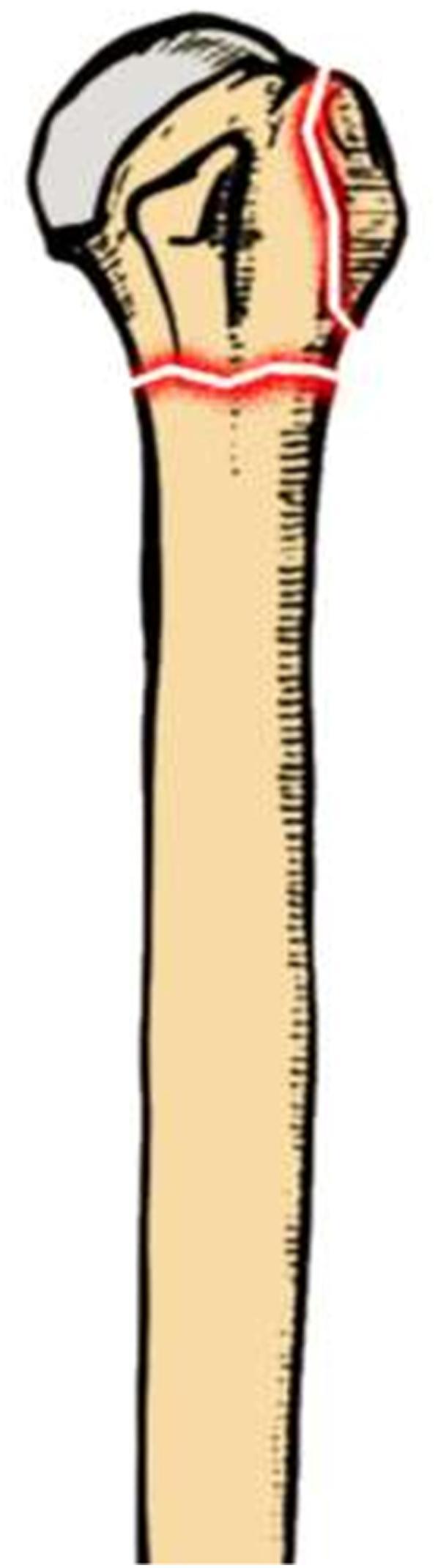
Anatomical illustration of a human proximal humerus depicting a displaced two-part fracture pattern. The diagram shows the humeral head, anatomical neck, and greater tuberosity regions. Red highlighted lines indicate fracture sites: a primary transverse fracture line across the surgical neck of the humerus and a secondary vertical fracture line involving the greater tuberosity and superior humeral head. The bone is rendered in a tan color with a gray articular surface for the glenoid fossa. This visual aid is designed for orthopedic education, specifically demonstrating the common components of Neer classification for proximal humeral fractures before surgical reduction and internal fixation.
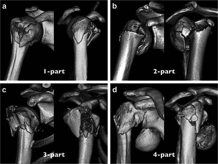
A comparison chart consisting of four 3D CT reconstructions (a-d) of the proximal humerus, illustrating the modified Neer classification system for humeral fractures based on fragment displacement and angulation. Each panel shows two views of the shoulder joint to demonstrate spatial relationships between the humeral head, greater tuberosity, lesser tuberosity, and humeral shaft. (a) 1-part fracture: Minimal to no displacement or angulation between segments; the humeral head maintains alignment with the shaft and tuberosities. (b) 2-part fracture: Visible fracture line with rotation or displacement (>1cm or >45°) of the humeral head and tuberosities relative to the shaft. (c) 3-part fracture: Separation involving three segments, typically with the humeral head detached from both the shaft and the greater tuberosity. (d) 4-part fracture: Complete detachment and significant displacement of the humeral head from the other three proximal humeral segments (shaft, greater, and lesser tuberosities). This visual resource is intended for orthopedic surgical education, specifically for classifying fracture severity and assessing articular surface vascular risk.
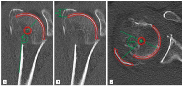
Diagnostic CT images of a right proximal humerus fracture (Neer type 4) demonstrating standardized radiological measurement techniques for fracture classification and fragment displacement. Panel A (coronal view) illustrates the head-shaft angle (HSA) measurement, utilizing a green line along the humeral shaft axis and a line intersecting the anatomical neck plane to assess for varus or non-varus alignment. Panel B (coronal view) displays the measurement of cranial displacement of the greater tuberosity in millimeters, indicated by vertical green markers. Panel C (axial view) shows the measurement of dorsal displacement of the greater tuberosity using an angular calculation. Across all panels, red outlines denote key anatomical fragments including the humeral head and greater tuberosity. These images provide a clinical methodology for evaluating orthopedic trauma, specifically relating to humeral head fractures and accompanying rotator cuff fragment position, which is critical for determining surgical intervention and prognostic outcomes in adult orthopedic medicine.
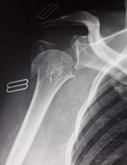
Anteroposterior (AP) radiograph of the right shoulder demonstrating a complex, comminuted proximal humerus fracture in an adult patient. According to the Neer classification system, this appears to be a 4-part fracture involving the surgical neck, the anatomical neck, and the greater tuberosity. Significant cortical disruption is visible, with multiple distinct bone fragments exhibiting displacement and angulation relative to the humeral shaft. The articular surface of the humeral head shows signs of involvement and spatial malalignment within the glenohumeral joint. There is also a visual suggestion of displacement of the greater tuberosity fragment. Radiopaque surgical clips are present in the soft tissues lateral to the humerus, likely from a previous or concurrent surgical procedure. The imaging is consistent with high-energy trauma or osteoporotic fragility fracture, illustrating the pedagogical challenge of identifying specific fracture lines in cases of severe comminution and overlapping fragments.
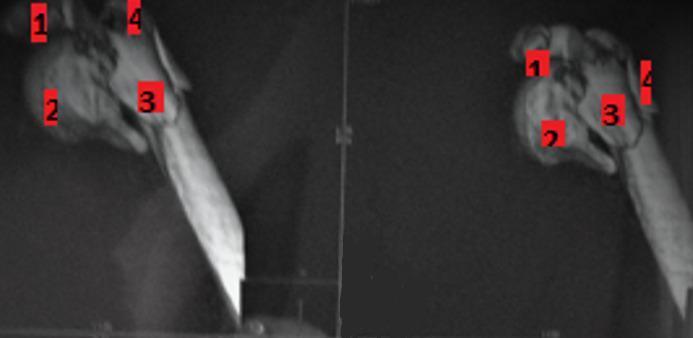
This diagnostic image consists of two Computed Tomography (CT) scan views (scout or 3D reformations) of the proximal humerus, demonstrating a complex 4-part fracture according to the Neer classification system. The image highlights a highly comminuted fracture involving the superior extremity of the humerus. Four distinct fragments are identified with red numerical labels (1 through 4): the articular humeral head, the greater tuberosity, the lesser tuberosity, and the humeral shaft (diaphysis). There is significant displacement and loss of anatomical alignment between the humeral head fragments and the surgical neck. The views (likely anteroposterior and a secondary oblique or axial orientation) provide a multi-planar assessment of the fracture pattern, crucial for surgical planning such as internal fixation with locking plates or arthroplasty. This clinical finding is typical of high-energy trauma in younger patients or low-energy falls in osteoporotic elderly populations within the domain of orthopedic traumatology.
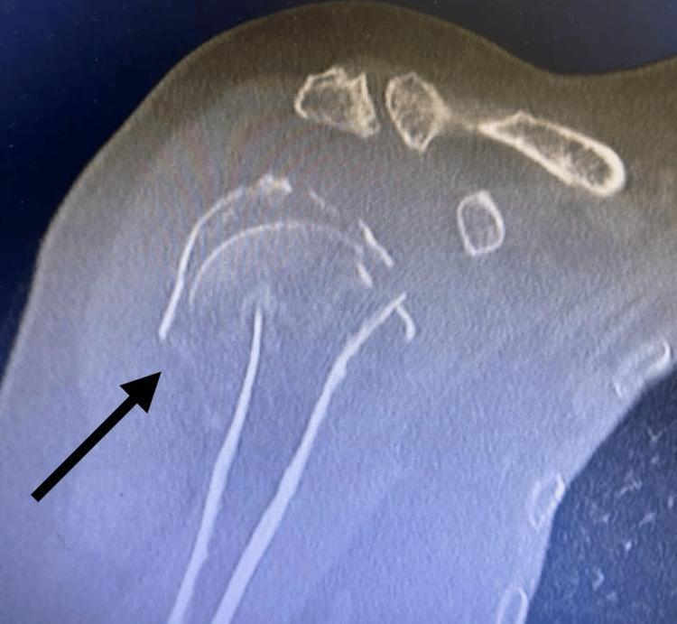
This diagnostic image is a Computed Tomography (CT) scan of the right shoulder, showing a severe proximal humerus fracture. The visual demonstrates a Neer four-part fracture pattern, characterized by the distinct separation and displacement of four major anatomical segments: the humeral head, the greater tuberosity, the lesser tuberosity, and the humeral shaft. An arrow points to the primary fracture site where significant cortical discontinuity is evident. There is a clear loss of normal anatomical alignment, with the humeral head appearing angulated and displaced relative to the glenoid fossa and the humeral shaft. The comminuted nature of the injury is visible through multiple bone fragments in the subacromial and glenohumeral regions. This image is used in medical education to illustrate complex orthopedic trauma, the Neer classification system for proximal humerus fractures, and the surgical considerations for management such as ORIF versus arthroplasty.
Neer's Classification of Proximal Humerus Fractures
The Four Anatomical Parts (Segments)
| Segment | Structure |
|---|---|
| 1 | Humeral head (articular surface) |
| 2 | Greater tuberosity |
| 3 | Lesser tuberosity |
| 4 | Humeral shaft (diaphysis) |
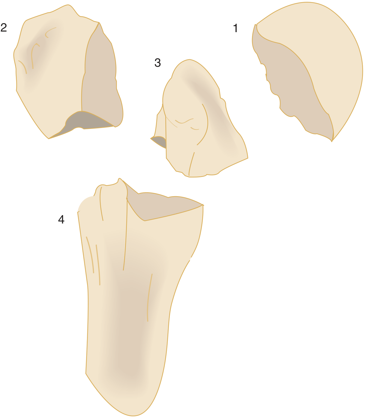
Displacement Criteria
- >1 cm of separation, OR
- >45 degrees of angulation
Classification Categories
1-Part Fracture (Undisplaced / Minimally Displaced)
- Any number of fracture lines present, but none meet the displacement criteria
- The periosteum and soft tissue hold the fragments in near-anatomical position
- ~80-85% of all proximal humerus fractures fall here
- Treatment: conservative (sling, early mobilization)
2-Part Fracture
| Subtype | Displaced Part | Notes |
|---|---|---|
| Anatomical neck | Humeral head | Rare; high AVN risk |
| Surgical neck | Shaft | Most common 2-part fracture |
| Greater tuberosity | Greater tuberosity | May accompany anterior dislocation |
| Lesser tuberosity | Lesser tuberosity | Often with posterior dislocation |
3-Part Fracture
4-Part Fracture
Fracture-Dislocation Variants
- "2-part anterior fracture-dislocation", "3-part posterior fracture-dislocation", etc.
- The fracture type is named first, then the direction of dislocation
Head-Splitting and Articular Surface Injuries
Visual Overview: CT Reconstruction of Neer Types

Treatment Implications
| Type | Typical Management |
|---|---|
| 1-part | Sling, early physiotherapy |
| 2-part surgical neck | Closed reduction + percutaneous pinning or ORIF |
| 2-part greater tuberosity | ORIF if displaced >5 mm (especially in athletes) |
| 3-part | ORIF with locking plate (younger patients); hemiarthroplasty in elderly |
| 4-part | Hemiarthroplasty or reverse total shoulder arthroplasty; ORIF in young patients with good bone stock |
| Head-splitting / anatomical neck | Arthroplasty (AVN risk very high) |
Limitations of the System
- Poor interobserver reliability - in one major study (Sidor et al.), all five observers agreed on the classification for only ~32% of cases; mean kappa was 0.48
- Difficulty in accurately measuring the 1 cm / 45-degree thresholds on plain radiographs
- Complex fracture patterns that do not fit neat categories
- CT scan improves reliability but does not fully resolve disagreements
Tibial plateau Fracture
Schatzker classification tibial plateau fracture types diagram
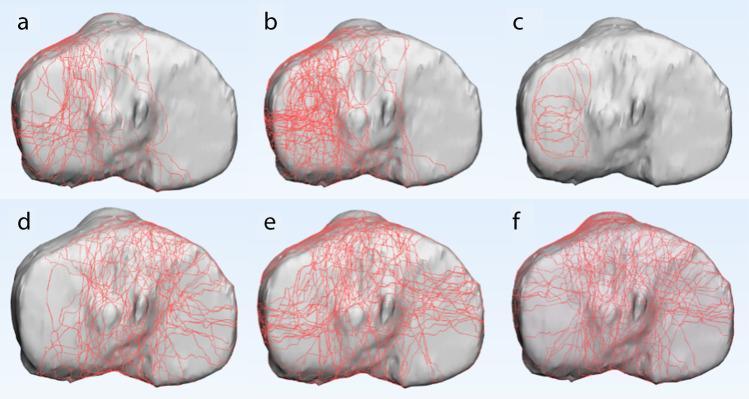
This diagnostic comparison chart presents six 3D reconstructions (labeled a–f) of a human left tibial plateau in an axial view, demonstrating fracture mapping across Schatzker types I–VI. Red lines represent anatomical fracture trajectories mapped onto a standard 3D tibial model. Panels 'a', 'b', and 'c' illustrate fractures primarily involving the lateral tibial plateau, consistent with Schatzker types I (pure cleavage), II (cleavage with depression), and III (pure depression). Panel 'b' specifically shows a higher density of comminution compared to 'a'. Panel 'd' represents Schatzker type IV, showing fracture lines localized to the medial plateau. Panels 'e' and 'f' represent Schatzker types V (bicondylar) and VI (bicondylar with metadiaphyseal dissociation), respectively, exhibiting extensive, high-density fracture networks that cross both medial and lateral compartments and the intercondylar eminence. This anatomical diagram serves as an educational tool for orthopedic surgical planning, highlighting fracture morphology and the distribution of mechanical failure across different injury mechanisms.
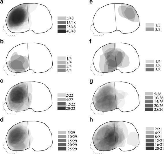
A series of eight grayscale heat maps (labeled a–h) illustrating the frequency and anatomical distribution of articular depression zones in various Schatzker classifications of tibial plateau fractures. The maps utilize a gray-value intensity scale to represent the incidence of depression at specific locations on the tibial plateau surface, with darker shades indicating higher frequency. (a-c) Schatzker type II subtypes: single anterolateral fracture (SALF) shows dense anterolateral depression; single posterolateral fracture (SPLF) shows a localized posterolateral zone; and complex fracture (CF) demonstrates a broad anterolateral distribution extending medially. (d) Schatzker type III shows concentrated lateral depression. (e-f) Schatzker type IV subtypes: single anteromedial fracture (SAMF) and whole medial fracture (WMF) showing varied medial plateau involvement. (g) Schatzker type V shows predominant posterolateral depression. (h) Schatzker type VI displays a central concentration of depression spanning the lateral and medial transition. This diagnostic illustration serves as an orthopedic educational tool for understanding fracture morphology and predicting articular surface damage based on fracture classification.
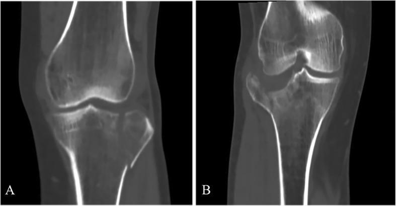
This diagnostic image displays two coronal CT reconstructions of the knee, illustrating different patterns of lateral tibial plateau fractures according to the Schatzker classification system. Image A shows a Schatzker Type I fracture, characterized by a simple vertical split of the lateral tibial condyle without significant depression of the articular surface. The fracture line is clean and extends from the lateral articular margin down into the metaphysis. Image B demonstrates a Schatzker Type II fracture, which consists of a lateral condylar split combined with a central articular depression. This depression is visible as a vertical 'step-off' in the joint surface, indicating a more complex injury mechanism typically involving both axial loading and valgus stress. Both images provide a clear comparison of articular congruity versus displacement, which is essential for determining surgical management. These patterns are common in orthopedic trauma and are critical for medical students and residents to differentiate during radiological assessment of knee injuries.
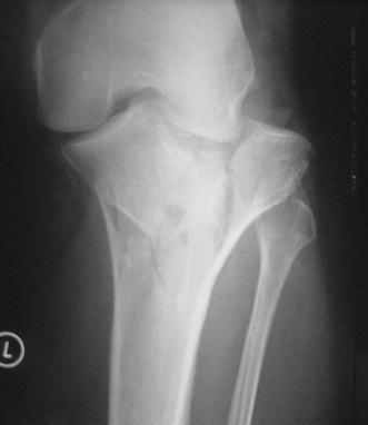
Anteroposterior (AP) pre-operative X-ray of the knee demonstrating a high-energy Schatzker type VI tibial plateau fracture. The diagnostic image shows a complex, comminuted fracture involving both the medial and lateral tibial condyles with significant disruption of the articular surface. A hallmark of the type VI classification is the complete dissociation between the tibial plateau (epiphysis/metaphysis) and the tibial shaft (diaphysis), visible here as multiple vertical and horizontal fracture lines extending through the proximal tibia. There is evident displacement of bone fragments and loss of joint congruity. Key landmarks including the distal femur and proximal fibula are visible, though the primary pathology is localized to the proximal tibia. This image is clinically significant for orthopedic surgical planning, highlighting the need for restoration of articular alignment and stable internal fixation in a multi-planar fracture pattern.

This diagnostic radiographic image consists of two views of the knee: (a) an antero-posterior (AP) view and (b) a lateral view, demonstrating a complex bicondylar tibial plateau fracture classified as Schatzker Type VI. The AP view reveals extensive comminution and disruption of both the medial and lateral tibial condyles, with multiple fracture lines extending from the articular surface through to the metaphysis. Significant distortion of the tibial plateau's anatomical contour is evident, along with a fracture of the proximal fibula. The lateral view demonstrates a complete dissociation between the tibial metaphysis and diaphysis. There is visible articular incongruity, depression of the joint surface, and significant anterior-posterior displacement of the fracture fragments. The images illustrate a high-energy orthopedic injury characterized by metaphyseal-diaphyseal discontinuity, which is the defining feature of the Schatzker VI classification. This content is highly relevant for orthopedic surgical planning, trauma education, and musculoskeletal radiology indexing.
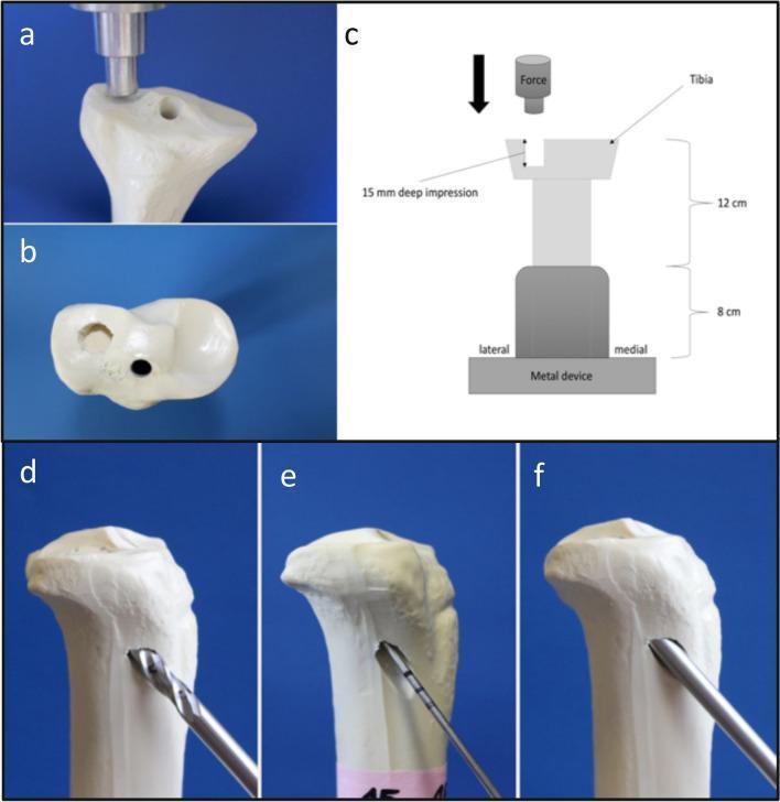
A multi-panel figure illustrating a biomechanical study of lateral tibial plateau depression fractures (Schatzker type III) using synthetic bone models. Panels (a) and (b) show the generation of a 15 mm deep depression fracture on the lateral tibial plateau using an axial indentor. Panel (c) provides a schematic diagram of the biomechanical test setup, showing a shortened tibia embedded in a metal device with axial force applied by a load cell. Panels (d), (e), and (f) demonstrate the step-by-step anatomical reduction process mimicking the Arthroscopic Reduction and Internal Fixation (ARIF) technique: (d) illustrates the lateral metaphyseal approach using a drill to create an entry point; (e) shows a Kirschner-wire (K-wire) used to detect and guide the depressed fragment; and (f) demonstrates the use of a cannulated ram to elevate the articular surface back to its anatomical position. This content serves to teach orthopedic trauma management, specifically the minimally invasive reduction of intra-articular proximal tibia fractures.
Tibial Plateau Fracture
Anatomy & Epidemiology
Mechanism of Injury
| Mechanism | Resultant Fracture Pattern |
|---|---|
| Axial load + valgus force (most common) | Lateral plateau split or depression (Types I-III) |
| Axial load + varus force | Medial plateau (Type IV) - high energy, rarer |
| Pure axial load (high energy) | Bicondylar (Types V-VI) |
| Direct blow / bumper injury | Metaphyseal-diaphyseal dissociation (Type VI) |
Schatzker Classification (1979) - Most Widely Used
Type I - Pure Cleavage (Lateral Split)
- Pattern: Sagittal split of the lateral tibial plateau creating a wedge-shaped fragment; no articular depression
- Mechanism: Valgus load in young patient with good bone quality
- Epidemiology: Least common Schatzker type (6/127 in one CT mapping study)
- Treatment: Percutaneous lag screw fixation; buttress plate if fragment is large and unstable
Type II - Cleavage + Articular Depression
- Pattern: Lateral plateau split fragment combined with depression of the articular surface (split-depression)
- Mechanism: Higher energy than Type I, or poor bone quality (older adults)
- Epidemiology: Most common Schatzker type (48/127 in same study)
- Treatment: ORIF - elevation of depressed fragment, bone graft to fill void, buttress/locking plate
Type III - Pure Depression
- Pattern: Depression of the articular surface of the lateral plateau without a peripheral split fracture
- Mechanism: Axial load in elderly patients with osteopenia/osteoporosis; femoral condyle is driven into soft subchondral bone
- Note: Recent evidence suggests "pure" Type III is extremely rare - most are Type II with undisplaced lateral cortex exit fracture lines
- Treatment: Similar to Type II: articular elevation, bone graft, buttress fixation
Type IV - Medial Condyle Fracture
- Pattern: Involves the medial tibial plateau (split, comminuted depression, or fracture through tibial spines); fracture lines may extend to lateral plateau
- Mechanism: Varus force (high energy); the medial condyle is much stronger than lateral, so significant force required
- Critical concern: High propensity for neurovascular injury (popliteal artery/peroneal nerve) and associated knee dislocation; ACL and MCL often remain attached to medial condyle while shaft displaces laterally; tends toward varus collapse if not fixed
- Treatment: ORIF; mandatory vascular assessment
Type V - Bicondylar Fracture
- Pattern: Both medial and lateral plateaus fractured, but metaphysis-diaphysis continuity maintained (the inverted Y fracture)
- Mechanism: High-energy axial load
- Treatment: ORIF - smaller undisplaced condyle fixed first with antiglide plate, then locking plate for the other side; dual-incision approach often needed
Type VI - Bicondylar + Metaphyseal Dissociation
- Pattern: Bicondylar plateau fracture with a complete dissociation of the articular surface from the tibial shaft (transverse or oblique metaphyseal fracture line); the most severe type
- Mechanism: Very high-energy axial loading (bumper/MVA, fall from height)
- Complications: High rates of open fracture, compartment syndrome, vascular injury, soft tissue stripping
- Treatment: Often staged - temporary spanning external fixator first (to allow soft tissue recovery), followed by definitive ORIF with locking plates; fasciotomy if compartment syndrome
Quick Reference Summary Table
| Type | Location | Pattern | Energy | Key Feature | Treatment |
|---|---|---|---|---|---|
| I | Lateral | Pure split | Low | Wedge fragment, no depression | Percutaneous screws |
| II | Lateral | Split + depression | Moderate | Most common type | ORIF, bone graft |
| III | Lateral | Pure depression | Low | Osteoporotic bone | Elevation, graft, plate |
| IV | Medial | Split/comminuted | High | Vascular injury risk | ORIF + vascular check |
| V | Bicondylar | Both condyles, shaft intact | High | Inverted "Y" | Dual-plate ORIF |
| VI | Bicondylar | + Metaphyseal dissociation | Very high | Shaft disconnected | Ex-fix then ORIF |
Associated Injuries
- Ligament injuries (71% of all tibial plateau fractures in Stannard et al.): ACL, PCL, MCL, LCL; more common with high-energy patterns
- Meniscal tears: Lateral meniscus tears especially with Types I-III; medial meniscus with Type IV
- Knee dislocation: Confirmed by MRI in 46% of Schatzker Type IV patterns
- Popliteal artery injury: Screen all high-energy fractures (Types IV, V, VI) with ABI; CT angiography if concern
- Compartment syndrome: Higher risk with high-energy fractures; must monitor closely especially with Type VI and fibular fractures
- Peroneal nerve injury: Particularly with Type IV varus injuries
Imaging
- Plain X-rays (AP + lateral + oblique): Initial assessment; Schatzker classification is X-ray based, but reliability is limited
- CT scan (axial + coronal + sagittal, with 3D reconstruction): Mandatory for all displaced fractures before surgery; reveals posterior condyle involvement, coronal fracture lines, and degree of comminution not seen on X-ray
- MRI: Best for ligament and meniscal assessment; changes treatment plan in a significant proportion of cases; recommended in Schatzker IV/V/VI
Additional Classification Systems
OTA/AO Classification (proximal tibia = "41")
- 41-A: Extra-articular (not true plateau fractures)
- 41-B: Partial articular (unicondylar)
- B1: Simple articular split
- B2: Split + depression
- B3: Comminuted split + depression
- 41-C: Complete articular (bicondylar)
- C1: Non-comminuted articular, simple metaphysis
- C2: Non-comminuted articular, comminuted metaphysis
- C3: Comminuted articular + comminuted metaphysis
Luo Three-Column Classification
- Zero-column: Pure depression (Schatzker III equivalent)
- One-column: Lateral only (Schatzker I/II)
- Two-column: Lateral + posteromedial (many Schatzker V/VI patterns)
- Three-column: All three involved
Limitations of the Schatzker System
- Does not classify fracture-dislocations
- Posterior shear/coronal plane fractures are not represented
- Some bicondylar patterns do not conform to Type V or VI
- Intercondylar eminence fractures with both plateaus broken but no shaft dissociation are uncategorized
- Interobserver reliability is imperfect on plain films alone; improves with CT
Fracture of patella
patellar fracture classification types transverse stellate comminuted vertical
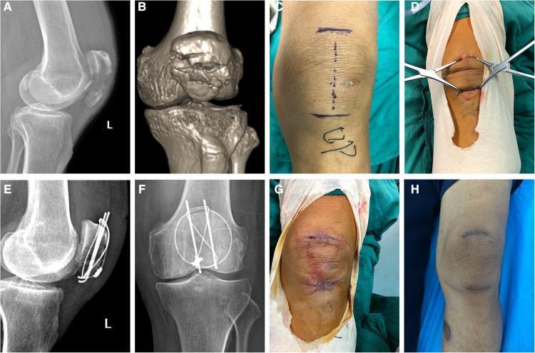
This composite panel illustrates the surgical management and healing progression of a comminuted patellar fracture in a 73-year-old patient. The diagnostic phase includes a lateral radiograph (A) and 3D CT reconstruction (B), demonstrating a displaced fracture with articular discontinuity. Intraoperative photographs show the minimally invasive technique: preoperative skin markings for dual transverse incisions (C), and the application of two-pointed bone reduction forceps (D). Postoperative radiographs (E, F) in lateral and anteroposterior views confirm successful fracture reduction and internal fixation using a combination of vertical Kirschner wires and a figure-of-eight tension-band titanium cable system. The clinical photographs document the wound healing timeline: (G) shows the immediate postoperative appearance with fresh sutures and localized ecchymosis, while (H) shows the three-month follow-up where the two small transverse scars are well-healed, showing minimal erythema and significant resolution of surrounding bruising. This series highlights orthopedic surgical principles including anatomical reduction, stable internal fixation, and the benefits of minimally invasive approaches in elderly populations.
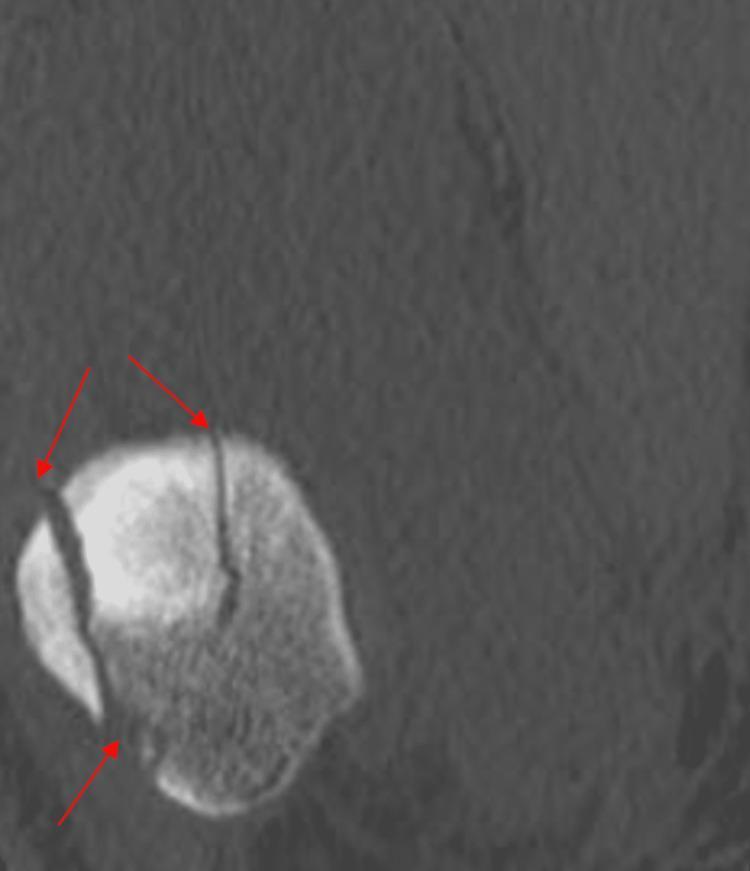
This diagnostic image is a coronal CT scan focused on the patella of the right knee. The scan demonstrates a comminuted patellar fracture, characterized by multiple fracture lines indicated by red arrows. Two distinct vertical fracture planes are visible, dividing the patella into at least three separate fragments. These fracture lines extend through the bony matrix, disrupting the cortical integrity and smoothing of the articular surface. The surrounding soft tissues show uniform density without gross displacement, though the primary focus remains on the integrity of the patellar bone. This image is illustrative of orthopedic trauma and the use of advanced imaging in assessing complex fracture patterns for surgical planning. It is intended for medical students and orthopedic residents to understand the classification and visualization of intra-articular knee fractures.
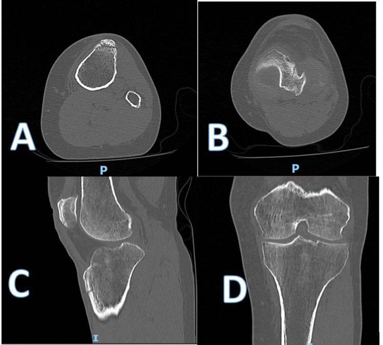
Multi-planar pre-operative Computed Tomography (CT) scan images of a left knee demonstrating complex traumatic fractures. Images A and B (axial views) show a minimally displaced transverse fracture through the inferior aspect of the patella and a comminuted fracture of the proximal tibia with cortical breaching. Image C (sagittal view) highlights an avulsion-type fracture of the tibial tuberosity. Image D (coronal view) reveals a vertical-oblique fracture line extending superiorly toward the tibial plateau, involving the intercondylar notch and causing a depressed fragment of the lateral tibial condyle. This clinical imaging set illustrates a synchronous injury involving both the extensor mechanism (patellar fracture) and the proximal tibial articular surface, specifically a type 4 pattern injury according to clinical classification. The diagnostic imaging is critical for surgical planning of open reduction and internal fixation (ORIF).
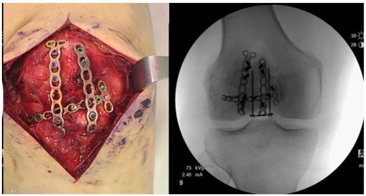
This composite figure illustrates the surgical management of a complex, comminuted patellar fracture (AO/OTA 34-C3). The left image is an intraoperative clinical photograph showing an open reduction and internal fixation (ORIF) procedure. Two parallel longitudinal 2.4 mm locking compression miniplates are positioned anteriorly, joined by a transverse plate to create a stable framework across the fracture fragments. Multiple color-coded locking screws are visible, securing the low-profile plates to the patellar bone. The right image is a corresponding anteroposterior (AP) fluoroscopic radiograph. It demonstrates the radiopaque hardware, including the miniplate construct and several long cannulated or locking screws, bridging the multi-fragmentary fracture lines. The radiographic view confirms the anatomical reduction of the patella and the multidirectional stabilization provided by the variable-angle locking system. This technique is typically employed for highly comminuted fractures where traditional tension band wiring may be insufficient for rigid fixation and early mobilization.
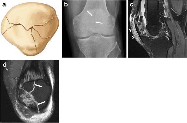
This composite educational resource illustrates a non-displaced stellate patellar fracture through four complementary views: (a) a medical illustration showing multiple radiating fracture lines, (b) an anteroposterior (AP) radiograph of the knee, (c) a sagittal fat-suppressed proton density (PD) MRI, and (d) a coronal fat-suppressed PD MRI. The AP radiograph reveals subtle lucent lines within the patella body (arrows). The MR images provide superior visualization of the multi-fragmentary, comminuted fracture pattern without significant displacement of the osseous fragments. The sagittal MRI (c) highlights hyperintense signal intensity in the prepatellar soft tissues (arrowheads), characteristic of subcutaneous oedema resulting from direct blunt trauma. This series serves as a clinical teaching tool for musculoskeletal radiology, emphasizing that patellar fractures occult or subtle on conventional radiography are better characterized using advanced imaging like MRI to assess for articular involvement and associated soft tissue injury.
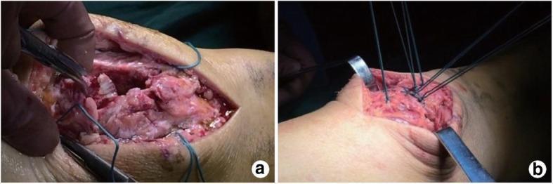
Two-part intraoperative clinical photograph demonstrating a 'three-dimensional strapping reduction' technique for a comminuted patellar fracture. Panel (a) shows the initial surgical exposure through a vertical incision, revealing multiple irregular bone fragments of the patella. Heavy blue non-absorbable sutures are seen being threaded from the fracture end through the patellofemoral joint into the surrounding soft tissue, with surgical forceps manipulating the tissue. Panel (b) illustrates the reduction phase where the sutures are gathered and tightened toward the center, effectively approximating the bone fragments under direct vision. The sutures are tied on the anterior surface of the patella, creating a stabilized construct before definitive internal fixation. This orthopedic procedure is designed to achieve anatomical reduction of the articular surface and the patellofemoral joint in complex fracture patterns.
Fracture of the Patella
Anatomy & Function of the Patella
- Increases the lever arm of the quadriceps, enhancing knee extension force by up to 50% depending on the angle of flexion
- Acts as a bony shield protecting the femoral condyles
- Distributes patellofemoral compressive forces over a wider surface area
Epidemiology
- ~1% of all skeletal fractures
- Peak incidence in young-to-middle-aged active adults (40s-50s)
- More common in males
- Bipartite patella (failure of ossification center fusion at the superolateral pole) must be differentiated from acute fracture - usually bilateral, smooth cortical margins
Mechanism of Injury
| Mechanism | Pattern Produced |
|---|---|
| Direct blow (dashboard, fall on flexed knee) | Stellate/comminuted; retinacula often intact |
| Indirect - sudden forceful quadriceps contraction (stumbling, eccentric load) | Transverse displaced; retinacula often torn |
| Combined direct + indirect | Mixed patterns |
Classification of Patellar Fractures
1. Displacement Criteria
- Nondisplaced: Fragment separation <3 mm AND articular incongruity <2 mm
- Displaced: Fragment separation ≥3 mm OR articular incongruity ≥2 mm
2. Fracture Pattern Types
Transverse (Horizontal)
- Most common overall pattern; majority occur in the middle to lower third
- ~35% are nondisplaced (indirect mechanism, retinacula intact)
- ~52% of displaced fractures are non-comminuted transverse
- Displaced transverse = high suspicion for retinacular/extensor mechanism tear
- Best seen on lateral radiograph
Stellate (Comminuted)
- Star-shaped radiating fracture lines from direct blow with knee partially flexed
- ~65% are nondisplaced; retinacula usually intact despite comminution
- When displaced: high-energy injury, often with skin contusion/lacerations - check for open fracture
- Occult osteochondral lesions are common - evaluate with tangential views or MRI
Vertical (Longitudinal)
- ~20% of patellar fractures
- Fracture line between middle and lateral third of patella most commonly
- Mechanism: lateral avulsion (most common) or direct compression in hyperflexed knee
- Retinacula are intact - active extension preserved
- Easily missed on AP view - axial (tangential/Merchant) view essential
- Displacement and retinacular disruption rare
Pole Fractures (Apical / Basal)
- Proximal pole (apical): Avulsion of the quadriceps mechanism; displacement rare (~4%)
- Distal pole (basal): Avulsion of the patellar tendon; sleeve fracture pattern in skeletally immature
- Active extension may be preserved if retinacula intact
- Lateral radiograph shows the pole avulsion; assess patellar height (Insall-Salvati ratio should be <1.2)
Osteochondral
- Involve the articular cartilage ± subchondral bone
- Often associated with patellar dislocation (medial facet + lateral femoral condyle)
- Best seen on axial/tangential views or MRI
- Important to identify intra-articular loose bodies
Sleeve Fracture (Pediatric)
- Unique to skeletally immature patients
- Avulsion of the distal pole of the patella with a large sleeve of articular cartilage
- The bony fragment may appear deceptively small on X-ray, underestimating the true cartilaginous injury extent
- Requires surgical repair
OTA Classification
- 34-A: Extra-articular (apophyseal)
- 34-B: Partial articular (unicondylar/marginal)
- 34-C: Complete articular (transverse, stellate, comminuted)
Clinical Assessment
- Hemarthrosis (tense, painful knee effusion)
- Palpable gap at fracture site
- Tenderness over the anterior patella
- Critical test: Ability to perform a straight leg raise or actively extend the knee against gravity
- Active extension preserved = retinacula likely intact = nonoperative treatment possible
- Extension lag or inability to extend = extensor mechanism disrupted = surgery required
Imaging
- AP view: Identifies transverse fractures; bipartite patella has well-corticated margins at superolateral pole
- Lateral view: Best view for assessing fracture pattern and fragment separation; assess patellar height; normal patellar tendon length ≈ sagittal patellar length (Insall-Salvati ratio < 1.2)
- Axial/Merchant view (45° flexion): Essential for vertical, marginal, and osteochondral fractures; articular incongruity best assessed here
- CT: Not routine; useful for preoperative planning, complex comminution, stress fractures, nonunion - but may over-indicate surgery when CT-based displacement measurements exceed radiograph-based thresholds
- MRI: Best for extensor mechanism integrity, ligament/tendon tears, occult chondral lesions; useful when radiographs are negative but fracture is suspected
Treatment
Goals of Treatment
- Maximal preservation of the patella
- Restoration of articular congruity
- Preservation of the extensor mechanism strength and integrity
Non-operative Treatment
- Intact extensor mechanism (patient can perform straight leg raise)
- Articular incongruity <3 mm
- Fragment separation <3 mm
- Severe medical comorbidity precluding anaesthesia
- Extension splint or cylinder cast (ankle to groin) for 4-6 weeks
- Weight bearing as tolerated in extension
- Isometric quadriceps exercises and straight leg raises from the start
- Gradual ROM after radiographic consolidation
- Repeat X-rays on starting ROM to check for displacement
Operative Treatment
- Fragment separation ≥3 mm or articular incongruity ≥2 mm
- Extensor mechanism disrupted
- Open fracture
- Loose intra-articular bone/cartilage fragments
A. Modified Anterior Tension Band Wiring (AO technique) - Gold Standard
- Two parallel K-wires or cannulated screws inserted longitudinally through both fragments
- Figure-of-eight 18-gauge wire placed anterior to the K-wires (or through cannulated screws)
- Converts distraction force from quadriceps into compression across the fracture during knee flexion
- Most commonly used for transverse and simple fractures
B. Longitudinal Anterior Band + Cerclage (Lotke-Ecker technique)
- For stellate/comminuted fractures not amenable to tension band alone
- Circumferential cerclage wire around the patella for initial reduction, followed by two parallel anterior longitudinal wires through drill tunnels
- Hybrid of anterior tension banding and intraosseous wire fixation
C. Plate Fixation
- Low-profile locking plates (single anterior plate or dual parallel plates joined transversely - "AO/OTA 34-C3" construct)
- Used for complex comminuted fractures where traditional tension band is insufficient
- Allows multidirectional stabilization and early mobilization
D. Partial Patellectomy
- Retain maximum patellar length - even small fragments improve extensor function
- The patella increases extension force by up to 50%; every retained fragment helps
- Tendon reattachment to anterior cortex (not articular surface) preferred biomechanically
- Outcomes comparable to ORIF when anatomic fixation is not possible
E. Total Patellectomy - Salvage Only
- Results in 49% reduction in quadriceps strength and ~18° loss of ROM
- High rates of instability, weakness, pain, and poor functional outcomes
- Must be avoided if any fragment can be preserved - even a single fragment substantially maintains the extensor lever arm
Complications
| Complication | Notes |
|---|---|
| Hardware irritation/prominence | Most common; reported in ~57% requiring implant removal |
| Anterior knee pain | ~80% with activities of daily living |
| Loss of knee flexion | Stiffness from immobilization or fracture |
| Patella baja | Shortening of patellar tendon, reduces patellar height |
| Nonunion / malunion | More common with inadequate fixation or poor bone quality |
| Post-traumatic arthritis | Related to articular incongruity; increasing age predicts worse outcomes |
| Wire/implant failure | Especially in osteoporotic bone; increasing age predicts fixation failure |
| Infection | Open fractures or wound complications |
| Avascular necrosis | Rare; more with pole fractures disrupting blood supply |