
Chest wall notes on this topic with images in simple language story like
chest wall anatomy ribs sternum muscles diagram
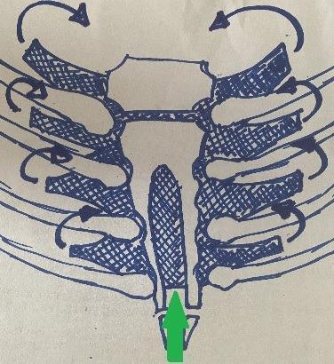
This medical illustration depicts an anatomical diagram of the anterior thoracic wall, specifically focusing on a surgical intervention for a lower bifid sternum (sternal cleft). The diagram shows the manubrium, the bilateral sternal bars, and the articulating ribs. A central gap is visible between the inferior portions of the sternal bars, representing the congenital defect. A green arrow points to a cross-hatched, oblong prosthesis positioned behind the sternum in the retrosternal plane. Black curved arrows indicate the vectors of mechanical approximation, illustrating how the prosthesis facilitates the medial transposition of the sternal bars to close the midline diastasis. The illustration serves as a pedagogical tool for pediatric thoracic surgery, demonstrating the use of a mesh or prosthetic graft to restore the structural integrity and biomechanical stability of the chest wall in cases of sternal malformation.
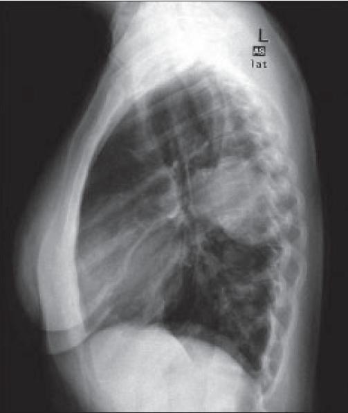
A lateral view chest radiograph (CXR) demonstrating the thoracic anatomy in profile. The imaging modality displays the sternum anteriorly as a vertically oriented, radio-opaque structure, with the thoracic spine and vertebral bodies visible posteriorly. The ribs are visualized as curved, superimposed radio-opaque bands extending from the posterior vertebrae toward the anterior chest wall with a typical slight upward slope. Centrally, the cardiac silhouette and hilar regions are visible, with pulmonary vasculature appearing as branching linear opacities. The lung fields are generally radiolucent, showing clear parenchyma without evidence of gross consolidation, masses, or pleural effusions. Key landmarks such as the retrosternal and retrocardiac spaces appear clear, and the diaphragmatic contours are visible inferiorly. This diagnostic image is representative of standard thoracic imaging for assessing pulmonary, cardiac, and musculoskeletal health in a clinical context.
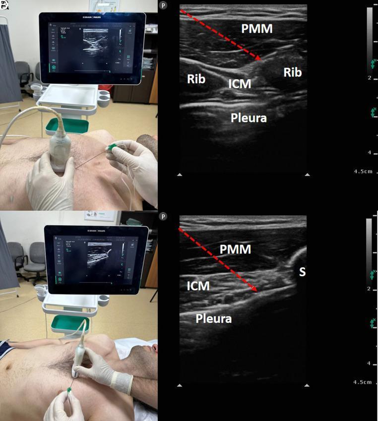
This composite clinical and diagnostic image demonstrates the technique and sonographic anatomy for parasternal intercostal plane (PIP) blocks. The left panels show clinical photographs of a linear ultrasound probe positioned on the anterior chest wall of a supine patient, aligned in parasagittal (top) and transverse (bottom) orientations near the sternal border, with a block needle being inserted in-plane. The right panels (labeled A-B and C-D in context) show corresponding high-frequency ultrasound views of the thoracic wall. Key anatomical layers identified include the pectoralis major muscle (PMM), intercostal muscles (ICM), and the hyperechoic pleural line. Ribs are visible as hyperechoic curved structures with posterior acoustic shadowing in the sagittal view, while the sternum (S) is seen in the transverse view. Red dashed arrows indicate the needle trajectory targeting the interfascial planes: the superficial PIP block (between PMM and ICM) and the deep PIP block (between ICM and the transversus thoracis/pleura). This material serves as a guide for regional anesthesia and pain management education.
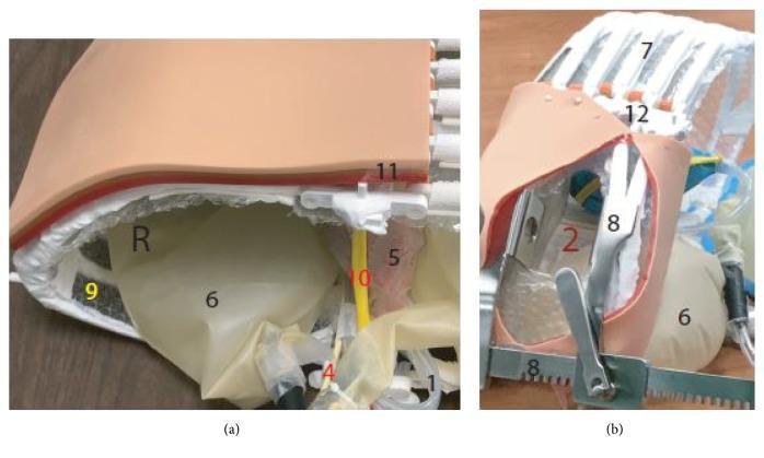
This composite image showcases a high-fidelity 3D-printed anatomical simulation model of the human chest cavity, designed for medical training in procedures such as emergency thoracotomy. Panel (a) provides a cross-sectional view of the multi-layered thoracic wall (11), composed of simulated skin, subcutaneous tissue, and muscle. Deep to the wall, the model illustrates the parietal pleura (9) and the right lung (6), alongside mediastinal structures including the heart within its pericardium (5), the phrenic nerve (10), and the esophagus (4). Panel (b) depicts the model with a rib spreader (8) in situ, retracting the simulated ribs (7) and sternum (12) to reveal the internal chest cavity (2). The construction utilizes a combination of 3D-printed polymers for skeletal structures and flexible synthetic materials to represent visceral organs and neurovascular bundles. This anatomical diagram serves as a tactile educational tool for surgical anatomy and procedural residency training, emphasizing the spatial relationships between the rib cage, lungs, and central mediastinal components.
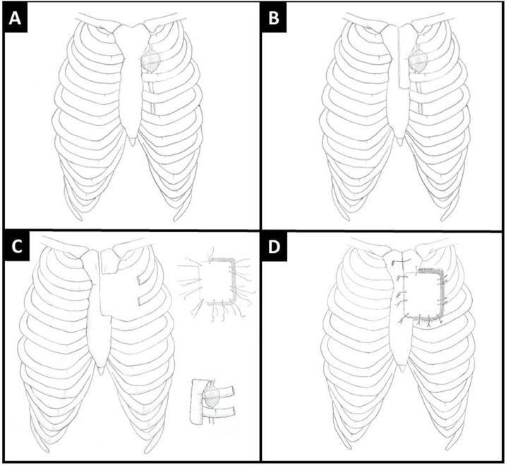
A four-panel (A-D) anatomical diagram illustrating radical en bloc resection and reconstruction of a chest wall defect following metastasis to the internal mammary lymph node (IMLN). Panel A shows the thoracic cage with a solitary metastatic IMLN located in the left parasternal region near the second and third ribs. Panel B depicts the surgical defect resulting from the resection of a portion of the manubrium, hemi-sternum, and the medial aspects of the second and third ribs. Panel C demonstrates the preparation of a methyl methacrylate (MMS) marlex mesh plate, showing the prosthesis alongside a detail of the radiating Prolene sutures used for anchoring. Panel D illustrates the final thoracic wall reconstruction, where the MMS plate is secured to the remaining sternum with wires and the peripheral mesh is sutured to the adjacent ribs and soft tissues to restore chest wall integrity. This illustration serves as an educational guide for thoracic surgeons regarding complex anterior chest wall resection and prosthetic reconstruction techniques.
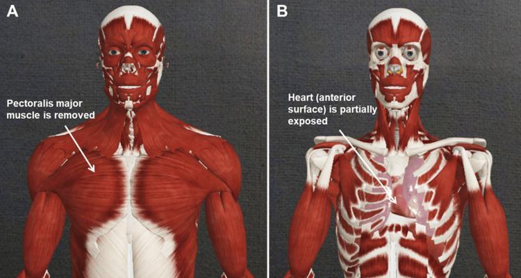
This comparative anatomical diagram displays two stages of a virtual dissection of the human head, neck, and thorax, highlighting the transition from superficial to deep structures. Image A (left) demonstrates the superficial musculature, prominently showing the pectoralis major muscles covering the anterior chest wall, along with the sternocleidomastoid, deltoids, and facial muscles. Image B (right) illustrates a deeper dissection plane where the pectoralis major and segments of the rib cage have been removed. This exposure reveals the underlying thoracic cavity, specifically showing the anterior surface of the heart (pericardium) and the internal skeletal framework, including the clavicles and individual ribs. Both images maintain consistent visualization of the head and neck musculature, such as the masseter and orbicularis oculi, as well as the biceps brachii in the upper limbs. The content is designed for medical education to teach thoracic anatomy, spatial relationships between the musculoskeletal system and internal organs, and the logic of surgical or anatomical dissection layers.
chest wall deformity pectus excavatum carinatum funnel chest
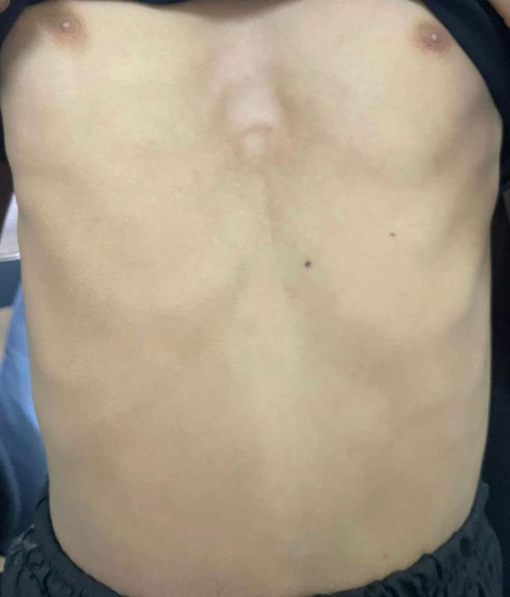
A clinical photograph of an anterior human chest demonstrating Pectus Excavatum, also known as 'funnel chest.' The image shows a notable concave depression of the sternum and lower costal cartilages. The deformity begins inferior to the nipple line and extends toward the xiphoid process, creating a sunken appearance in the central chest wall. The skin covering the area is intact with visible contours of the adjacent rib cage and minor cutaneous nevi on the upper abdominal region. This visual finding is characteristic of a congenital chest wall deformity where the breastbone sinks into the chest, which can vary in severity. The image provides an educational example of thoracic wall musculoskeletal pathology relevant to pediatrics, thoracic surgery, and physical examination training.
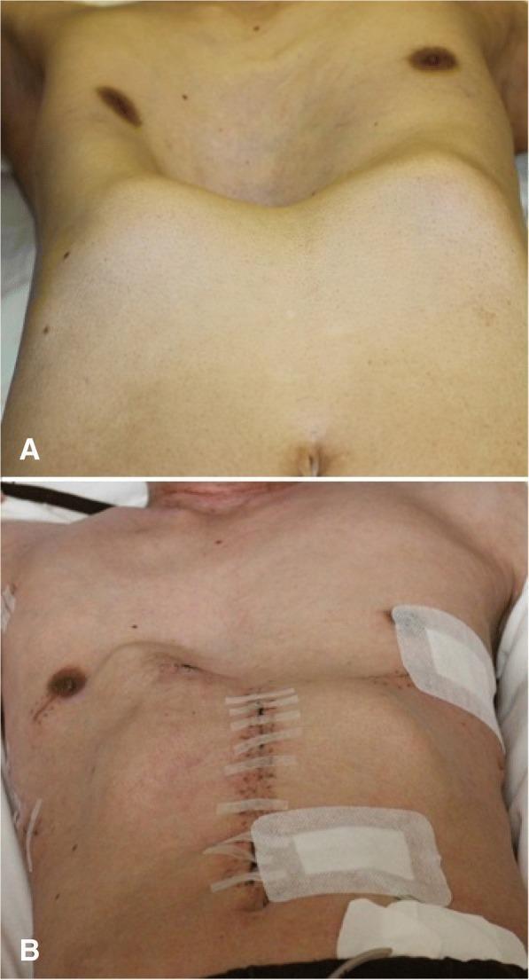
This clinical photograph set presents a pre- and post-operative comparison of a patient with pectus excavatum (funnel chest). Image A depicts the preoperative state, showing a severe congenital chest wall deformity characterized by a deep, central concavity of the sternum. This depression creates a funnel-like appearance with the sternal notch significantly recessed compared to the lateral ribcage and abdominal plane. Image B shows the same patient following surgical correction (Nuss procedure). The chest wall contour is markedly improved, with the sternum repositioned anteriorly to create a more physiological, convex chest profile. Surgical indicators are visible, including a vertical midline incision closed with sutures and adhesive strips (Steristrips), alongside lateral surgical dressings over the thoracic entry points for the metal bars used in the reconstruction. This comparison illustrates the effective anatomical remodeling of the thoracic cavity to increase mediastinal space.
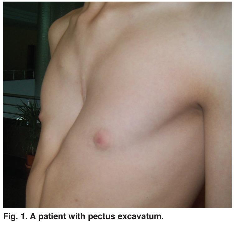
This clinical photograph shows a three-quarter view of a patient's torso, illustrating a classic presentation of pectus excavatum (funnel chest). The primary feature is a significant posterior depression of the sternum and adjacent costal cartilages, resulting in a concave anterior chest wall. The deformity is centered on the lower half of the sternum, with a slight lateral asymmetry where the left hemi-thorax appears more deeply recessed than the right. The skin overlying the deformity is intact, smooth, and free of surgical scars, lesions, or vascular abnormalities. The bony landmarks of the shoulder girdle and clavicles appear normal, while the subcutaneous fat is minimal, highlighting the skeletal indentation. This image serves as an educational example of a congenital chest wall deformity, relevant for thoracic surgery and pediatric orthopedics, specifically for evaluating morphological severity prior to surgical interventions such as the Nuss or Ravitch procedures.
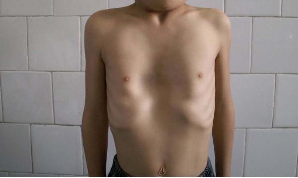
This clinical photograph shows the anterior torso of an 8-year-old male demonstrating a classic presentation of pectus excavatum, a congenital chest wall deformity. The primary feature is a significant posterior depression of the sternum and adjacent costal cartilages, resulting in a sunken or 'funnel chest' appearance. The indentation is most pronounced in the mid-to-lower sternal region, just above the epigastrium. Visually, this creates a hollowed central chest cavity with a compensatory outward appearance of the lateral ribcage and lower costal margins. The patient exhibits slight protraction of the shoulders and a slender habitus, common postural associations with this condition. This image serves as an educational example of musculoskeletal pathology in pediatric thoracic surgery and orthopedics, illustrating the visual manifestations used to assess the severity of chest wall malformations.
flail chest rib fracture multiple trauma
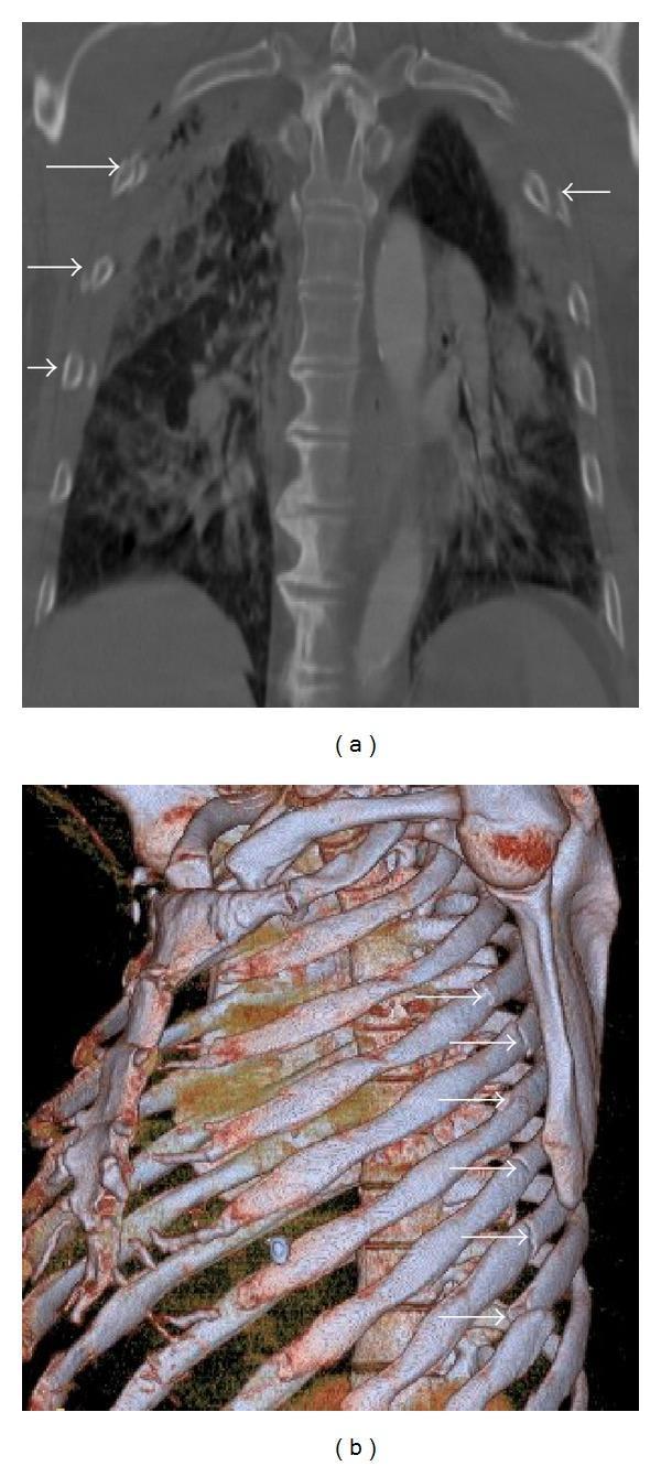
This composite diagnostic image showcases thoracic trauma findings using Multidetector Computed Tomography (MDCT). Figure (a) is a coronal CT reformat in a bone window demonstrating a 'flail chest' scenario. Multiple displaced rib fractures are identified by white arrows across consecutive costal arches on the right side and a single fracture on the left. The underlying lung parenchyma displays heterogeneous, patchy 'ground-glass' opacities and ill-defined consolidations, characteristic of pulmonary contusions resulting from blunt chest trauma. Figure (b) presents an oblique sagittal volume-rendering (3D) reconstruction of the thoracic cage. This visualization highlights the structural discontinuity of the thoracic wall, clearly demarcating a series of multiple rib fractures (indicated by arrows) along the posterior and lateral aspects of the left ribs. These images are essential for medical education regarding the radiological assessment of polytrauma, illustrating the relationship between skeletal injury (rib fractures) and parenchymal lung damage (contusions) in emergency radiology.
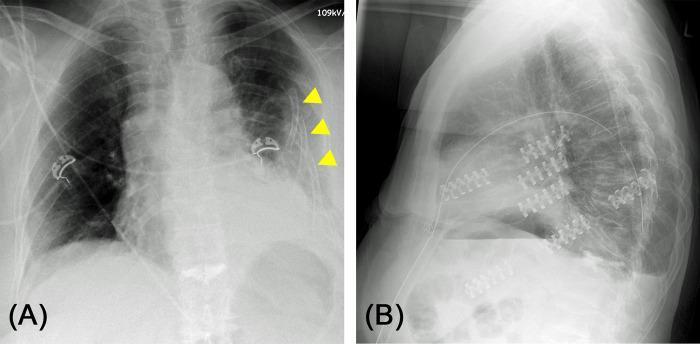
This figure presents two diagnostic chest X-rays demonstrating the surgical management of severe thoracic trauma. Image (A) is an anteroposterior (AP) view showing extensive, significantly dislocated serial rib fractures on the left side, involving ribs 1 through 11. Several ribs exhibit multiple fracture lines creating free-floating segments, characteristic of a 'flail chest' or 'floating rib' pathology. The yellow arrows highlight the lateral areas of significant displacement where the physiological contour of the rib cage is lost. Image (B) is a post-operative lateral X-ray showing the results of surgical stabilization via osteosynthesis. Radiopaque metallic hardware, including specialized plates and screws, is visible on ribs 4 through 7. This internal fixation has restored the physiological contour and structural stability of the thorax. The images illustrate the clinical progression from acute flail chest deformity to post-surgical stabilization, emphasizing that selective osteosynthesis of key segments can successfully stabilize the entire chest wall and improve respiratory mechanics.
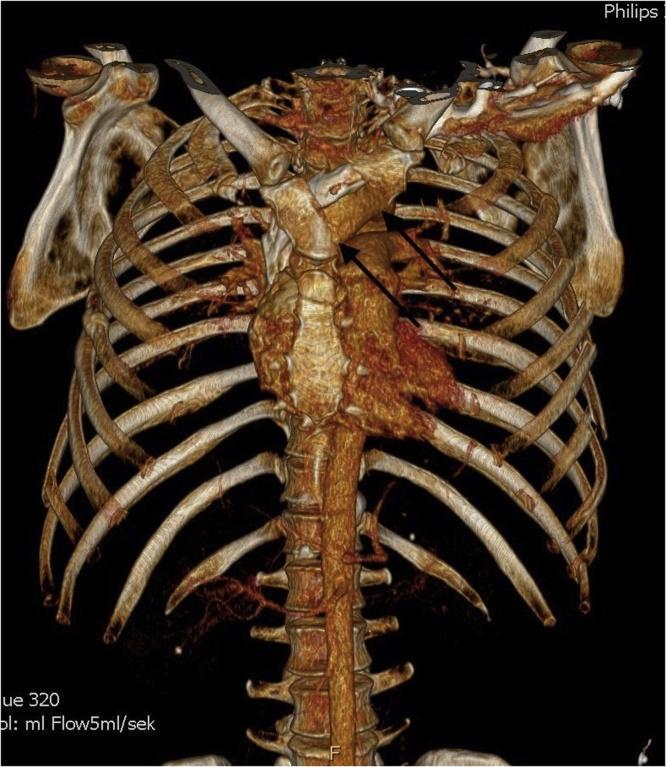
This diagnostic image is a 3D Volume Rendering Technique (VRT) reconstruction of a thoracic CT scan, showing the anterior ribcage, sternum, and thoracic spine of a trauma patient. The visual highlights a clinical flail chest injury. Multiple rib fractures are evident on the left side of the ribcage, specifically manifesting as lateral costal fractures and an anterior fracture line. The sternum is also compromised; two black arrows point to a transverse fracture through the manubrium. The 3D reconstruction provides a clear spatial orientation of the skeletal instability, demonstrating the disrupted integrity of the chest wall. Key anatomical landmarks include the clavicles, manubrium, body of the sternum, ribs, and vertebral column. This image is used for educational purposes to demonstrate complex thoracic trauma, surgical planning for rib fixation, and the radiological appearance of unstable chest wall injuries in a clinical emergency context.
chest wall tumor resection reconstruction thoracic
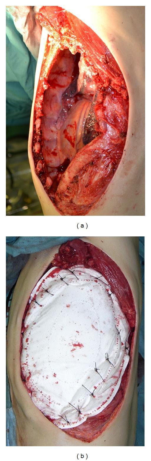
Two intraoperative clinical photographs demonstrate a thoracotomy for chest wall tumor resection and subsequent reconstruction in a 74-year-old patient. Photograph (a) shows the defect immediately following an en bloc resection of a large tumor involving the 4th through 8th ribs. The thoracic cavity is exposed, revealing internal structures, visible rib edges, and surrounding musculature. Photograph (b) illustrates the primary reconstruction phase using a Composix E/X Mesh, a dual-sided prosthesis composed of expanded polytetrafluoroethylene (ePTFE) and polypropylene. The white, elliptical mesh is seen secured to the surrounding intercostal muscles and rib margins with heavy non-absorbable sutures to restore chest wall integrity and stability. This visual serves as an educational example of managing massive chest wall defects requiring synthetic mesh stabilization to prevent paradoxical breathing and protect intrathoracic organs.
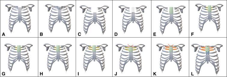
This surgical schematic algorithm illustrates a twelve-step procedure (Panels A–L) for complex chest wall reconstruction following tumor resection. The diagrams depict the thoracic cage, including the sternum, ribs, and clavicles. The sequence begins with the identification of a tumor involving the manubrium and sternoclavicular joints (B), followed by wide surgical resection of the superior sternum, medial clavicles, and adjacent ribs (C). The reconstruction phase (D–L) demonstrates the creation of a neosternum and chest wall stabilization using a combination of prosthetic materials. Key steps include the placement of a vascular graft (Hemashield) over the sternal stump (E), the use of titanium rib plates (F–G) and clavicular plates (H) for structural support, and the application of bone cement (orange) within latex molds to recreate rib and sternal volume (I–K). A sternal cable system is utilized to bridge the clavicular stumps (J–L), mimicking the function of the sternoclavicular joint. The final panel (L) shows the completed modular reconstruction, restoring anatomical integrity and thoracic stability through integrated cement, plates, and cables.
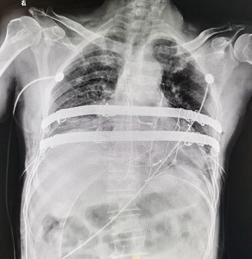
Postoperative anterior-posterior (AP) chest X-ray demonstrating surgical reconstruction of the anterior chest wall following a sternal tumor resection. The image shows two prominent, radiopaque horizontal steel bars positioned parallel across the central thoracic region. These bars are part of a 'Wenlin procedure' used for chest wall stabilization, with their distal ends anchored to adjacent ribs. Fine radiopaque steel wires are visible, forming a mesh-like configuration between the bars and the surrounding ribs to provide structural reinforcement to the resection site. Multiple medical devices are present, including bilateral thoracic drainage tubes extending toward the lower thorax and ECG leads on the upper chest. The skeletal structure shows a clear absence of the central sternal body, indicating the extent of the surgical resection. This diagnostic image illustrates complex thoracic reconstruction techniques using metallic implants to restore chest wall integrity and maintain respiratory mechanics.
🏠 The Chest Wall - A Story of the Body's Fortress
Chapter 1: Building the Fortress - Anatomy
- The roof - the thoracic inlet (top opening)
- The floor - the diaphragm
- The walls - ribs, sternum (breastbone), and vertebrae (spine)
- Pectoralis major & minor - front guards (chest muscles)
- Serratus anterior - side guards (under the arm)
- Latissimus dorsi - back guards (large back muscle)
- Intercostal muscles - fill the spaces between each rib
The Fortress has three jobs:
- Protect the heart and lungs inside
- Support the neck, arms, and abdomen
- Power breathing - the negative pressure on inhale sucks air in, the positive pressure on exhale pushes air (and voice!) out
Chapter 2: When the Fortress is Born Wrong - Congenital Deformities
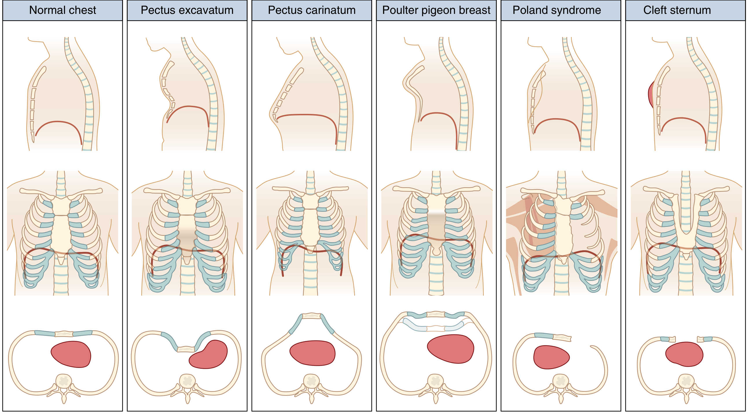
🕳️ Pectus Excavatum - "The Sunken Chest"
- Most common chest wall deformity: 1 in 400 births
- Male predominance 4:1
- Can be linked to Marfan syndrome or Noonan syndrome
- Patients complain of poor exercise tolerance, chest discomfort, and shortness of breath - and of course, appearance
Haller Index = Transverse diameter of chest ÷ Anterior-posterior diameter at narrowest point Normal = ~2.5 | Surgery needed if >3.25
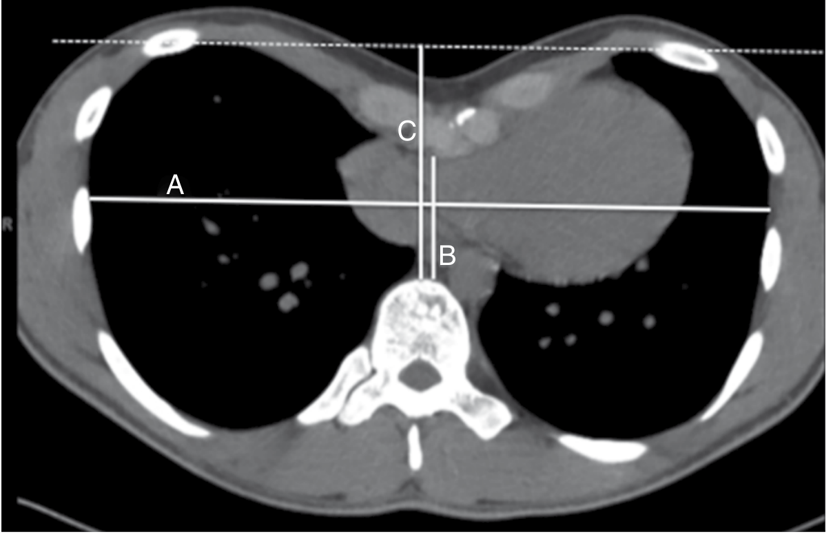
- Nuss Procedure - Minimally invasive. A custom curved steel bar is slid behind the sternum and flipped to push it forward. Like inserting a key under a locked door and lifting it.
- Ravitch Procedure - Open surgery. The deformed cartilages are removed and the sternum is repositioned.
🐦 Pectus Carinatum - "The Pigeon Chest"
🇵🇱 Poland Syndrome - "The Missing Wall"
- Unilateral - affects only one side
- Associated with absence of pectoralis muscles and breast tissue on that side
- Reconstruction with muscle flaps (e.g., latissimus dorsi transfer) can restore the chest contour
⚡ Cleft Sternum - "The Open Gate"
Chapter 3: The Fortress Under Attack - Chest Wall Trauma
🦴 Rib Fractures
- Ribs 1-3 fractured = HIGH energy trauma - worry about great vessels (aorta, subclavian)
- Ribs 4-9 fractured = Most common
- Ribs 10-12 fractured = Worry about spleen (left) or liver (right) injury underneath
💥 Flail Chest - "The Paradoxical Wall"
The floating segment is sucked inward by the negative pressure of inspiration - reducing lung expansion and making breathing exhausting.
- Pain control first (epidural analgesia is gold standard)
- Mechanical ventilation for respiratory failure (the ventilator acts as an internal splint)
- Surgical rib fixation (ORIF) - plates and screws to pin the ribs back in place - increasingly used in modern practice
🔗 Sternal Fractures
Chapter 4: Uninvited Guests - Chest Wall Tumors
- Benign: Osteochondroma (most common benign rib tumor), fibrous dysplasia, chondroma
- Malignant: Chondrosarcoma (most common primary malignant), Ewing sarcoma (young patients!), osteosarcoma, plasmacytoma
A painful enlarging chest wall mass in a young person = think Ewing Sarcoma A painful mass in an older adult = think Chondrosarcoma or metastasis
Chapter 5: The Fortress Gets Infected - Chest Wall Infections
- Costochondritis - Infection/inflammation of the rib-cartilage junction. Common, usually self-limiting, treated with NSAIDs. Also called Tietze syndrome when a lump is present.
- Sternal wound infection - After open heart surgery (sternotomy). Can progress to mediastinitis - a life-threatening deep infection. Requires debridement and reconstruction with muscle flaps.
- Empyema necessitans - Pus from a lung empyema erodes through the chest wall and surfaces under the skin.
Chapter 6: The Fortress Gate Gets Squeezed - Thoracic Outlet Syndrome (TOS)
| Type | Structure Compressed | Most Common Patients | Key Symptoms |
|---|---|---|---|
| Neurogenic TOS | Brachial plexus (nerve) | Young women (3.5:1) | Pain, tingling down the arm to ring/little finger, arm weakness |
| Venous TOS | Subclavian vein | Young athletic males | Arm swelling, bluish discoloration (Paget-Schroetter syndrome) |
| Arterial TOS | Subclavian artery | Young adults, equal sex | White, cold, painful hand; risk of arterial clot |
Chapter 7: Breathing and the Flexible Fortress
- Normal breathing: The ribs rotate upward and outward in a "bucket handle" motion. The sternum moves forward like a "pump handle." Together they increase chest volume, pulling air in.
- Diaphragm is the real MVP, contributing 70-80% of breathing effort.
- Ankylosing spondylitis - Inflammatory arthritis fuses the spine and rib joints. The bucket handle can't swing. Breathing becomes stiff, and forced breathing is lost. Patients can't cough well and get pneumonias.
- Kyphoscoliosis - Abnormal spinal curvature twists and deforms the ribs, reducing lung volume and making the respiratory muscles work inefficiently.
Quick Summary - The Fortress at a Glance 🗝️
| Topic | Key Point |
|---|---|
| Anatomy | Ribs + sternum + vertebrae + muscles (pec major, serratus, intercostals) |
| Pectus excavatum | Sunken sternum; most common deformity; Haller index >3.25 = surgery |
| Pectus carinatum | Protruding sternum; brace treatment |
| Poland syndrome | Absent pectoralis ± rib/hand anomaly |
| Rib fracture | Pain control; watch ribs 1-3 (vessels) and 10-12 (organs) |
| Flail chest | 3+ ribs broken in 2 places = paradoxical movement; treat pain + ventilate |
| Chest wall tumor | Chondrosarcoma (adults), Ewing sarcoma (young); wide resection |
| TOS | Gate at top squeezed; nerve (90%+), vein, or artery compressed |
| Ankylosing spondylitis | Rigid chest = restrictive lung disease + poor cough |
No I want the proper anatomy of chest wall
chest wall anatomy layers intercostal muscles nerves vessels cross section
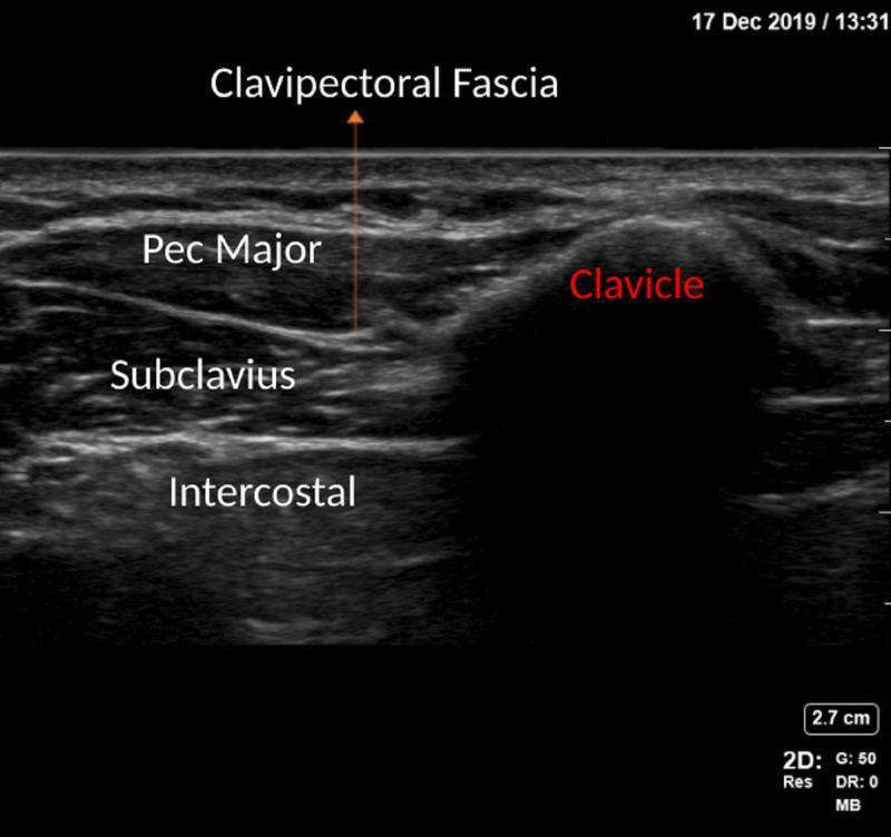
This diagnostic image is a high-frequency linear ultrasound scan of the anterior chest wall, specifically showcasing the anatomical landmarks for a Clavipectoral Fascia Block (CPB). The scan displays a layered cross-section of musculoskeletal structures. Superficially, the Pectoralis Major (Pec Major) muscle appears as a hypoechoic band. Deep to this, the Clavipectoral Fascia is identified as a hyperechoic interface separating the pectoralis major from the underlying Subclavius muscle. In the deeper field, hypoechoic Intercostal muscles are visible. To the right of the muscular layers, the Clavicle is presented as a prominent, hyperechoic convex surface that produces a distinct posterior acoustic shadow, obscuring deeper structures. This imaging provides clinical guidance for regional anesthesia, allowing for the precise identification of the fascial plane where local anesthetic is typically deposited to manage pain related to clavicular fractures or upper thoracic surgeries.
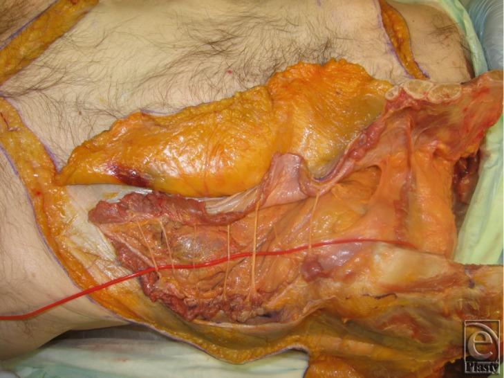
This clinical anatomical photograph shows a deep surgical dissection of a human cadaver's right thoracoabdominal region, illustrating the procurement of an osteomyofasciocutaneous allograft. The image reveals a 6-cm segment of the chest wall including three vertebrochondral ribs that have been completely released; their cross-sections clearly show the internal bone marrow. The rectus abdominis muscle remains attached to the inferior aspect of these ribs. Segmental intercostal thoracolumbar nerves are visible as thin, longitudinal cords traversing the plane between the internal oblique and transversus abdominis layers. A red latex-injected blood vessel (representing the deep inferior epigastric or internal mammary system) is highlighted, demonstrating its anatomical course. Adipocutaneous flaps and underlying muscle fascia are reflected to expose the deep surgical field. This specimen demonstrates the surgical anatomy necessary for functional abdominal wall transplantation and complex reconstructive surgery involving neurovascular and bony components.
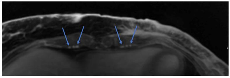
This diagnostic image is an axial cross-section of a chest Magnetic Resonance Angiography (MRA) scan. The view focuses on the anterior thoracic wall, showing the sternum, subcutaneous fat, and muscle layers. The primary clinical focus is the identification of recipient vessels for microsurgical anastomosis in preoperative planning for autologous breast reconstruction (e.g., DIEP flap). Blue arrows bilaterally indicate the internal mammary veins, which appear as hyperintense (bright), small, circular structures located adjacent to the internal mammary arteries. The image demonstrates the spatial relationship and caliber of these thoracic vessels relative to the intercostal spaces and sternal border. This imaging modality is used to assess the viability and anatomic course of the internal mammary system to ensure successful microvascular outcomes during reconstructive surgery.
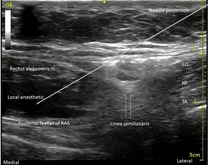
An ultrasound diagnostic image demonstrating a transversus abdominis plane (TAP) and rectus sheath block procedure. The image displays the anterolateral abdominal wall musculature in cross-section. On the right (lateral aspect), three distinct muscle layers are visible: the external oblique (EO), internal oblique (IO), and transversus abdominis (TA) muscles, separated by hyperechoic fascial planes. Progressing medially, the linea semilunaris marks the transition where these muscles meet the rectus abdominis muscle. A white line indicates the 'Needle projection,' showing an in-plane approach from lateral to medial. The needle tip terminates between the rectus abdominis muscle and the hyperechoic posterior leaflet of the rectus abdominis sheath (RAS). A significant hypoechoic (dark) area is labeled 'Local anesthetic,' illustrating the successful hydrodissection and spread of injectate within the posterior rectus sheath plane. This visual serves as a clinical guide for regional anesthesia, highlighting essential landmarks for ultrasound-guided nerve blocks of the T7-T12 intercostal nerves.
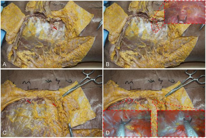
This composite of four clinical photographs (A-D) demonstrates the surgical anatomy of the chest wall relevant to transaxillary endoscopic breast augmentation. Figure A shows a dissected view of the fourth intercostal space with a red arrow identifying a vascular bundle emerging from the intercostal region toward the pectoralis major muscle. Figure B includes an endoscopic inset showing the visualization of this vascular anatomy in a lower pocket. Figure C illustrates the medial boundary near the lateral edge of the sternum, where red arrows point to neurovascular bundles located in the 2–3 and 4–5 intercostal spaces. Figure D demonstrates the surgical management of these vessels using an ultrasonic scalpel, with endoscopic insets showing the precise disconnection of the intercostal perforators. The images highlight critical landmarks for creating the subpectoral cavity while protecting nipple sensation and minimizing postoperative hematoma. Key structures visible include the pectoralis major, intercostal muscles, adipose tissue, and various surgical instruments used for blunt and sharp dissection.
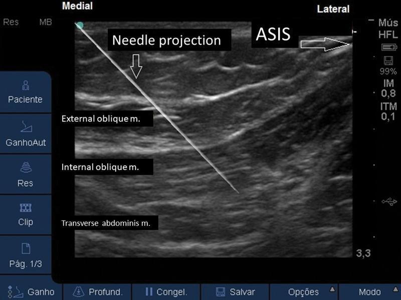
This diagnostic ultrasound image demonstrates the anatomy of the anterolateral abdominal wall for an ultrasound-guided regional anesthesia procedure, specifically an Ilioguinal/Iliohypogastric (II/IH) nerve block. The cross-sectional view displays three distinct muscle layers from superficial to deep: the external oblique, internal oblique, and transverse abdominis muscles. The muscles appear as relatively hypoechoic bands separated by bright, hyperechoic fascial planes. Laterally, the anterior superior iliac spine (ASIS) is identified as a hyperechoic bony landmark. A needle is visualized in-plane, appearing as a sharp, linear hyperechoic structure. It follows a medial-to-lateral trajectory, with its tip precisely positioned in the neurovascular fascial plane between the internal oblique and the transverse abdominis muscles. This placement is clinically significant for the delivery of local anesthetic to target the nerves supplying the lower abdominal wall. The image serves as an educational guide for identifying relevant landmarks and verifying correct needle tip placement during interventional pain management or surgical anesthesia.
thoracic wall ribs sternum costal cartilage anatomy labeled diagram
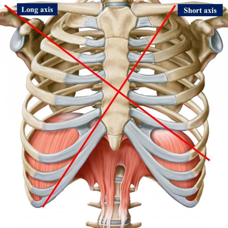
This anatomical diagram provides an anterior view of the human thoracic cage and upper abdominal musculature. The skeletal framework consists of the sternum (manubrium, body, and xiphoid process), articulating ribs with prominent costal cartilages, and components of the shoulder girdle, including the clavicles and glenoid cavities. Two intersecting red lines represent the long and short axes used for cardiac surface projection and surgical landmarks: the 'Long axis' extends from the right shoulder toward the left epigastrium, and the 'Short axis' extends from the left mid-clavicular region toward the right chondrocostal ramp. Inferiorly, the muscular diaphragm is depicted with its dome-like morphology and central tendon, alongside the superior attachments of the rectus abdominis muscle. The diagram serves as a clinical reference for surface anatomy, illustrating the spatial relationships between the thoracic wall and the underlying mediastinal structures, specifically for identifying cardiac chambers and valve locations in medical and osteopathic education.
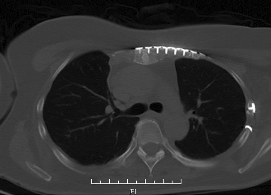
A transverse (axial) section of a CT scan of the thorax demonstrating postoperative internal fixation of costal cartilage fractures. The image reveals multiple radiopaque metallic hardware components, including long threaded plates and screws, positioned along the left anterior chest wall. The plates span the costal cartilages and are secured medially to the sternum and laterally to the osseous segments of the ribs. The lung parenchyma appears well-aerated with visible vascular markings. Anatomical landmarks include the sternum anteriorly, the thoracic spine and vertebral body posteriorly, and the bilateral ribs. The image illustrates a surgical management strategy for chest wall trauma, specifically focusing on the stabilization of costal cartilage fractures using titanium plating systems.
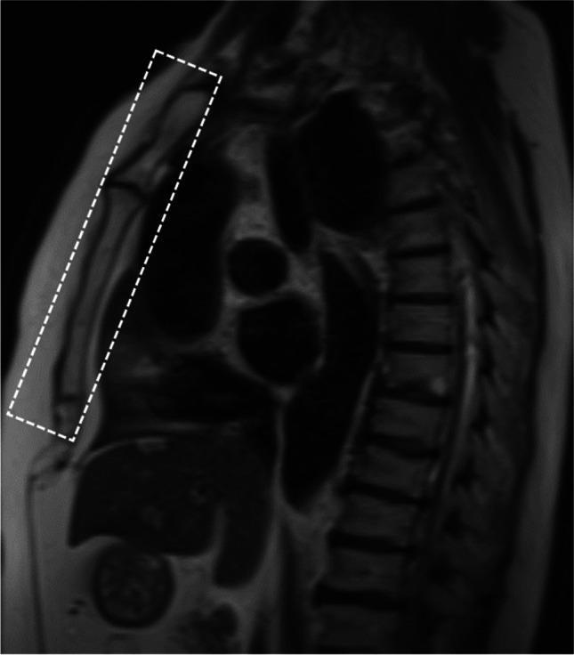
This diagnostic image is a magnetic resonance imaging (MRI) scan of the thoracic region, presented in a coronal oblique orientation. The plane of the scan is specifically aligned parallel to the sternum to optimize the visualization of the anterior chest wall structures. Anatomical landmarks visible include the sternum and costal cartilages anteriorly (highlighted within a dashed rectangular box), the thoracic spine posteriorly, and the intercostal spaces. The signal intensity across the image reflects varying tissue densities: the bony structures of the vertebrae and ribs demonstrate low signal intensity (darker), while the soft tissues, including the costal cartilage and pectoral muscles, show intermediate signal intensity. This specific imaging protocol is utilized in clinical settings to evaluate chest wall trauma, specifically to detect costal cartilage fractures, dislocations, or inflammatory changes such as edema that may not be readily apparent on standard axial CT or plain radiographs.
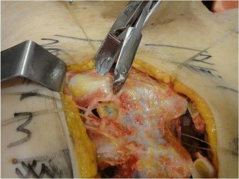
This clinical photograph captures a surgical procedure involving the resection of costal cartilage at the sternal junction, likely during a thoracic dissection or access procedure. The central focus is on a small metallic costotome (cartilage-cutting instrument) as it engages with the pale, whitish, and semi-translucent costal cartilage. The surgical field is exposed via a median longitudinal incision, held open by a metal retractor. Multiple tissue layers are discernible: the outermost yellow subcutaneous adipose tissue, underlying reddish-pink intercostal musculature, and associated connective tissues. Visible anatomical landmarks include the parasternal region where the cartilage joins the sternum. Pre-operative or intra-operative markings are visible on the skin surrounding the incision. The image demonstrates the precise mechanical step of chondrotomy, essential for procedures requiring rib cage expansion or internal thoracic artery/node access. It serves as an educational resource for thoracic surgery, surgical anatomy of the chest wall, and instrument application.
sternum anatomy manubrium body xiphoid sternal angle angle of Louis labeled
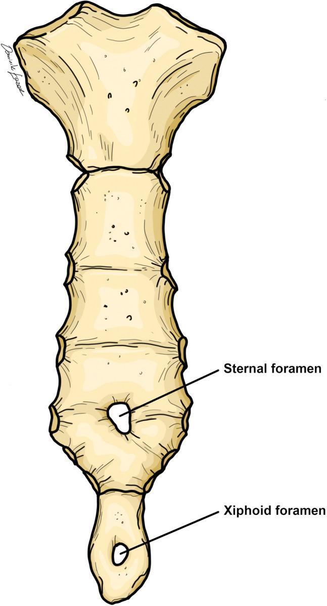
This anatomical diagram illustrates the anterior view of a human sternum, highlighting common congenital variations. The illustration clearly defines the three primary segments: the superior manubrium, the elongated segmented body (gladiolus), and the inferior xiphoid process. Two distinct developmental defects are labeled: a 'Sternal foramen' located in the inferior third of the sternal body and a 'Xiphoid foramen' situated centrally within the xiphoid process. Both foramina are depicted as circular perforations through the bone. These anatomical variants result from the incomplete midline fusion of the cartilaginous sternal bars during embryological development. The image serves as an educational tool for clinical anatomy and radiology, emphasizing the importance of recognizing these benign variants to avoid misinterpretation as pathology (such as lytic lesions) or potential complications during medical procedures like sternal punctures or acupuncture.
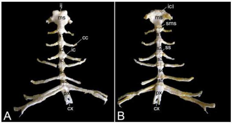
This clinical anatomical photograph displays the sternum of a hamadryas baboon in two perspectives: Ventral view (A) and Dorsal view (B). The image illustrates the segmented skeletal structure typical of the primate thorax. Key anatomical components labeled include the cranial-most manubrium sterni (ms), the sternal body composed of five distinct sternebrae (s1-s5), and the caudal processus xiphoideus (px) with its associated xiphoid cartilage (cx). The ventral view (A) clearly demonstrates the costal notches (ic) and articulating costal cartilages (cc). The dorsal view (B) provides enhanced visualization of the cartilaginous joints, specifically the manubriosternal synchondrosis (sms) and the sternal synchondroses (ss) between sternebrae. Notable manubrial landmarks include the jugular notch (ij) at the cranial midline and the bilateral clavicular notches (icl) for articulation with the shoulder girdle. This comparison serves as a high-level educational resource for comparative primate osteology and thoracic anatomy, highlighting morphological variations in articulatory surfaces.
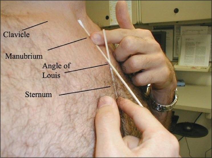
A clinical photograph and procedural image illustrating the surface anatomy and landmarks of the upper thoracic region. The image depicts a clinician's hands identifying and palpating key anatomical structures on a patient's chest for the purpose of placing a radiopaque marker. Labeled anatomical landmarks from superior to inferior include the clavicle, manubrium, angle of Louis (sternal angle), and the body of the sternum. The clinician is using a cotton swab and a thin rod as temporary external markers to localize the angle of Louis, which serves as a critical clinical reference point for assessing central venous catheter tip positioning. The photograph demonstrates the anatomical relationship between the manubriosternal junction and surrounding thoracic structures, highlighting its relevance in critical care and radiology for ensuring optimal procedural placement within a specified range above or below the sternal angle.
🏗️ Chest Wall Anatomy - The Body's Living Cage
🦴 Part 1: The Skeleton - Bones & Cartilage
THE RIBS (12 Pairs)
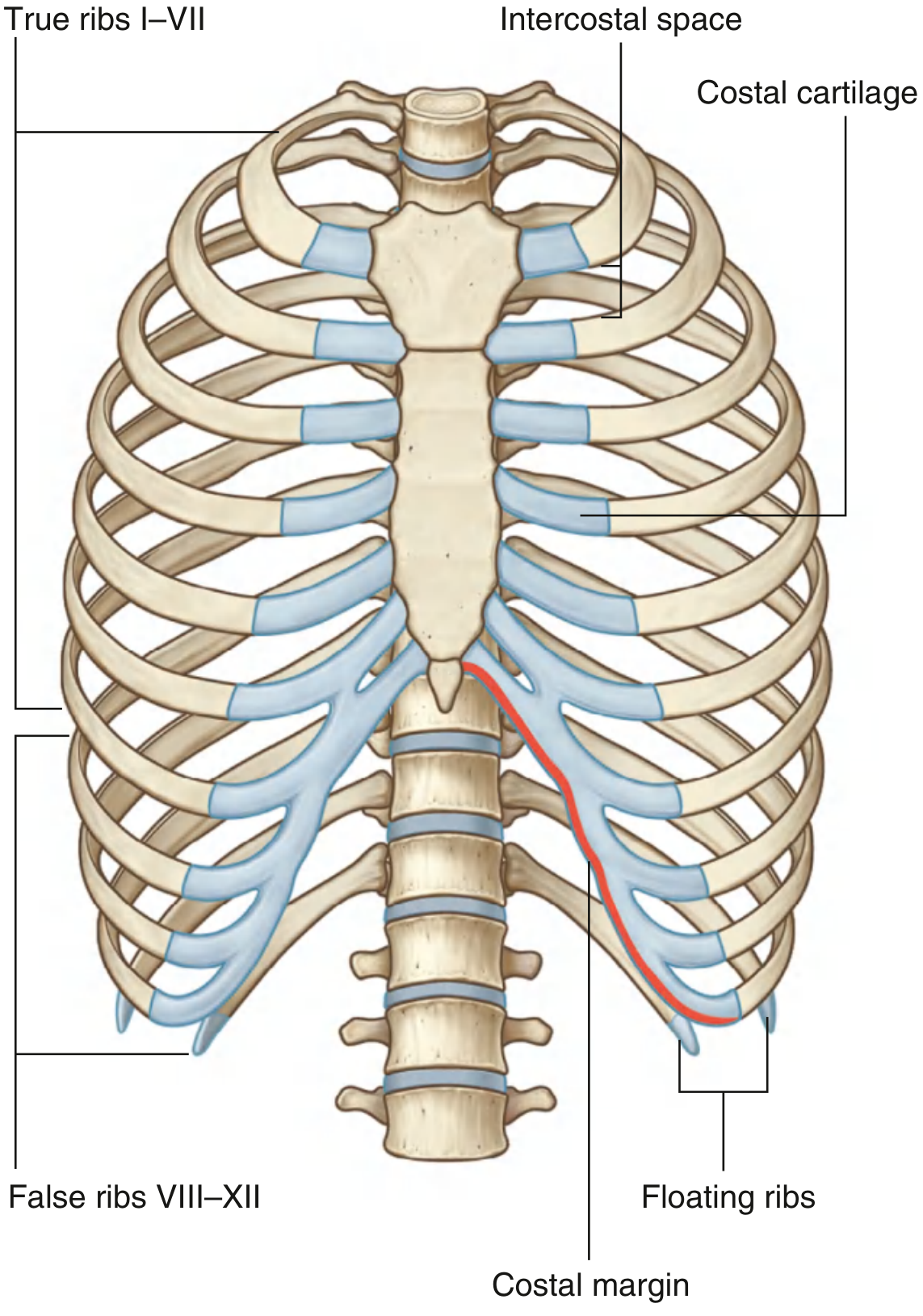
| Type | Ribs | How they connect to sternum |
|---|---|---|
| True ribs | 1-7 | Directly, via their own costal cartilage |
| False ribs | 8-10 | Indirectly - they share the cartilage of the rib above |
| Floating ribs | 11 & 12 | Don't reach - they end freely in the abdominal muscles |
ANATOMY OF A TYPICAL RIB (Ribs 3-9)
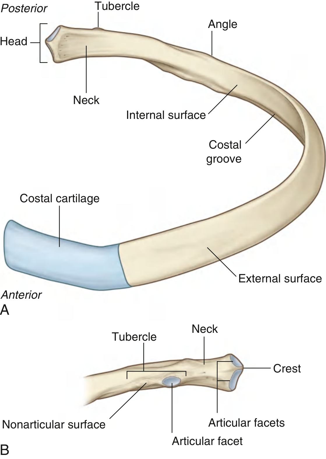
- Head - the "plug" that fits into the vertebral body. Has two demi-facets - one for its own vertebra and one for the vertebra above
- Neck - short, flat segment between the head and tubercle
- Tubercle - small bump that articulates with the transverse process of the same-numbered vertebra
- Angle - the sharpest curve of the rib, where it abruptly turns anterolaterally. This is where rib fractures most commonly occur!
- Shaft (Body) - the long curved part; rounded on top, thin and flat below. The thin inferior edge forms the costal groove - the important highway where the neurovascular bundle runs
- Costal cartilage - the blue "flexible tip" at the front that connects the rib to the sternum (or to another cartilage)
Key clinical point: The costal groove runs along the inferior (lower) edge of each rib. This is where the nerve, artery, and vein hide - so always insert a needle/chest tube just above the upper border of a rib, not below it.
ATYPICAL RIBS
THE STERNUM
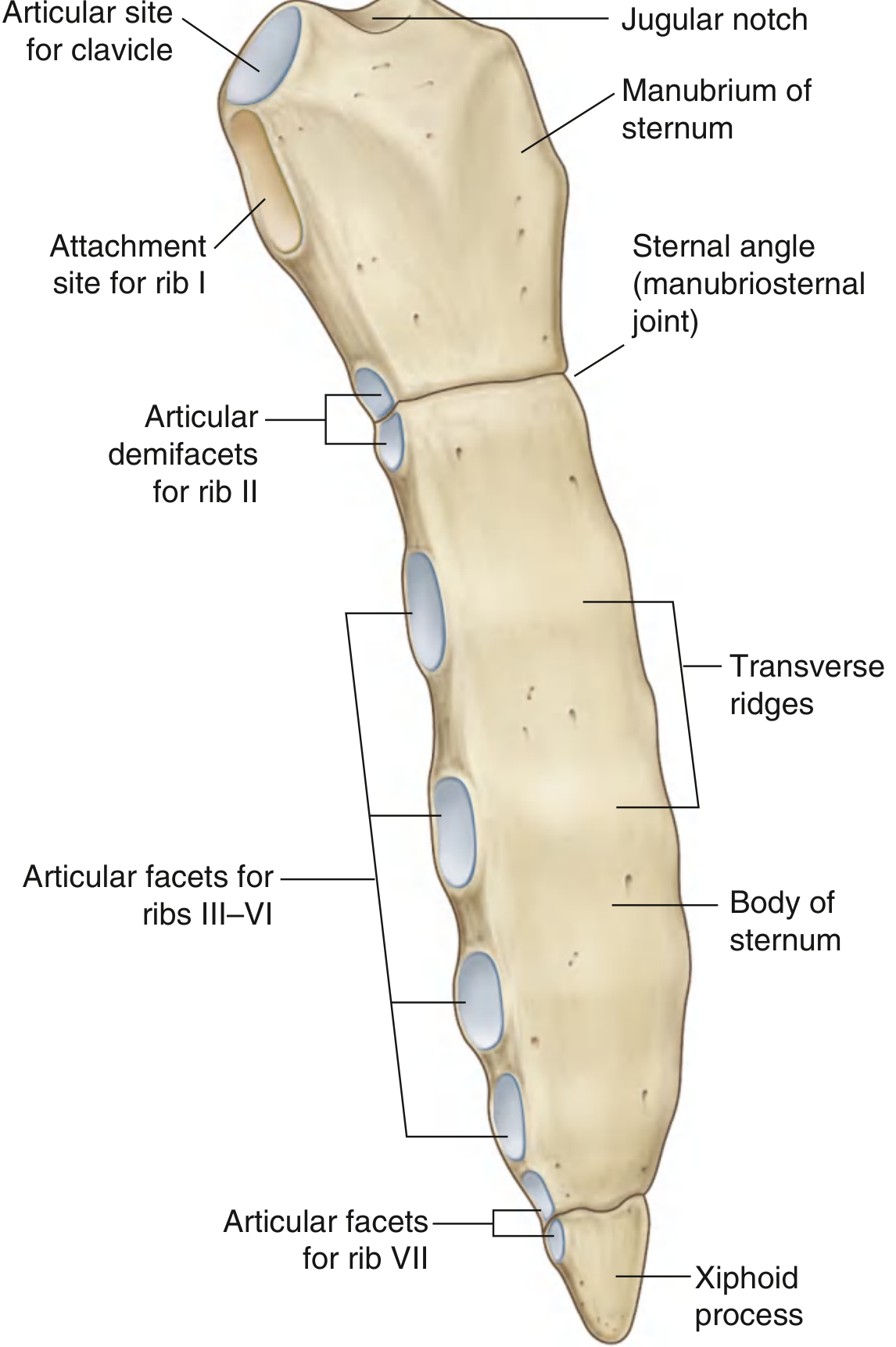
- Widest, thickest part
- Jugular (suprasternal) notch at the top center - you can feel this on yourself!
- Clavicular facets on either side of the jugular notch (for the sternoclavicular joints)
- Facet for rib 1 on each lateral surface
- Demi-facet inferiorly for the upper half of rib 2 cartilage
- Long, flat, narrow
- Transverse ridges on its front surface = fusion lines of the embryological sternebrae
- Articulations on lateral edges: ribs 2 to 7
- Smallest part; variable shape (can be pointed, bifid, or even perforated)
- Starts as cartilage in the child, ossifies in the adult
- Attachment for diaphragm, rectus abdominis, and linea alba
- Xiphisternal joint = level of T9
The junction between manubrium and body = the sternal angle (manubriosternal joint). This is one of the most important surface landmarks in the body:
- Marks the articulation of rib 2 (your starting point to count ribs downward)
- Lies at the level of the T4/T5 disc
- Marks the start and end of the aortic arch
- Level of the carina (where the trachea splits)
- Upper border of the superior mediastinum
💪 Part 2: The Muscles - Three Layers Deep
INTRINSIC MUSCLES - The Intercostal Muscles
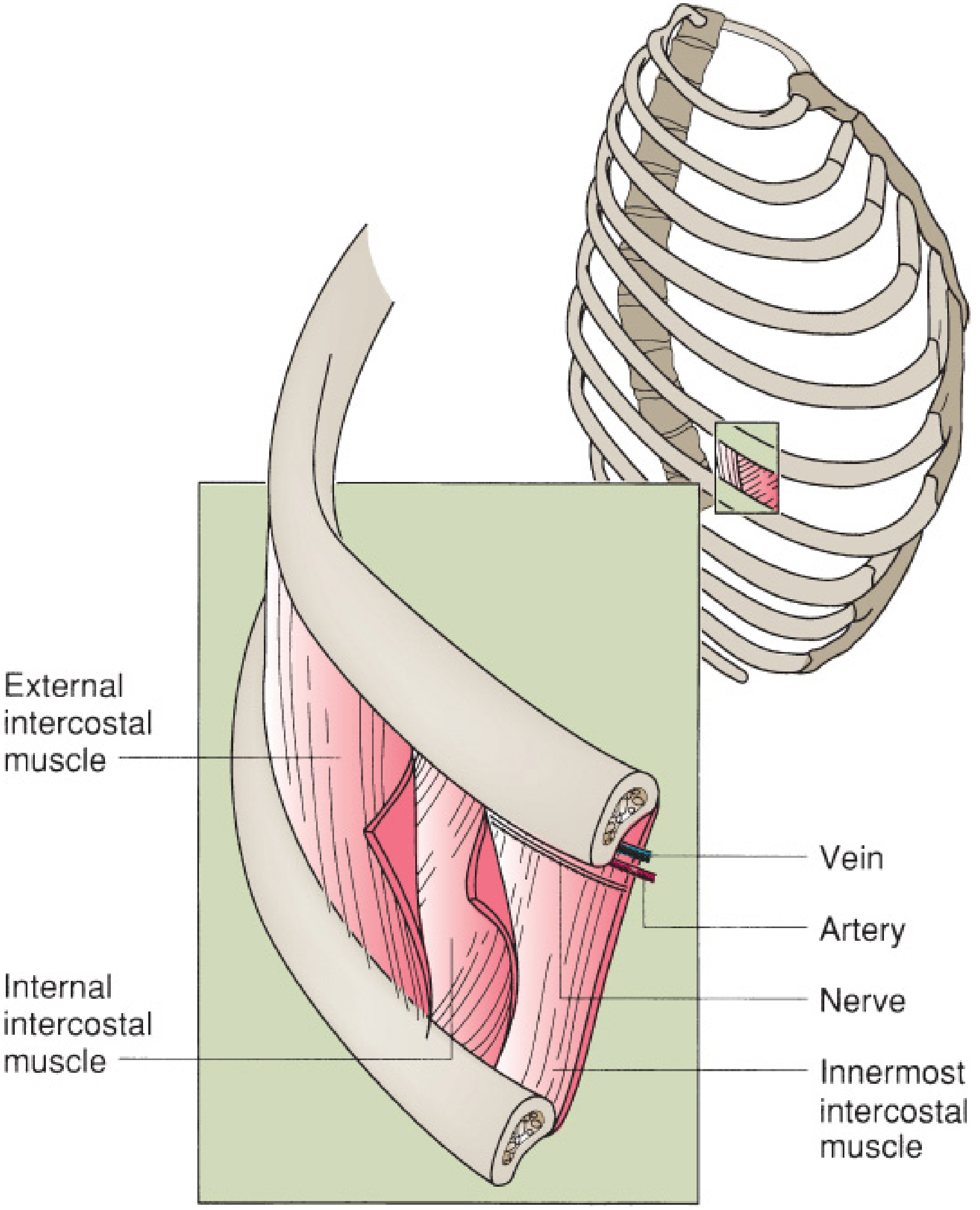
- Fibers run downward and forward (like hands in pockets)
- Run from rib tubercles → costochondral junction
- Anterior to the costochondral junction, replaced by the external intercostal membrane
- Action: elevates ribs during inspiration (active breathing in)
- Fibers run downward and backward (opposite to external) - perpendicular to external layer
- Run from sternum → angle of ribs
- Posterior to the angle, replaced by the internal intercostal membrane
- Action: lower portion depresses ribs during forced expiration
- Only in the lateral parts of the intercostal space
- Same fiber direction as internal intercostal
- Also includes transversus thoracis on the inner front wall (connects lower sternum to costal cartilages 2-6)
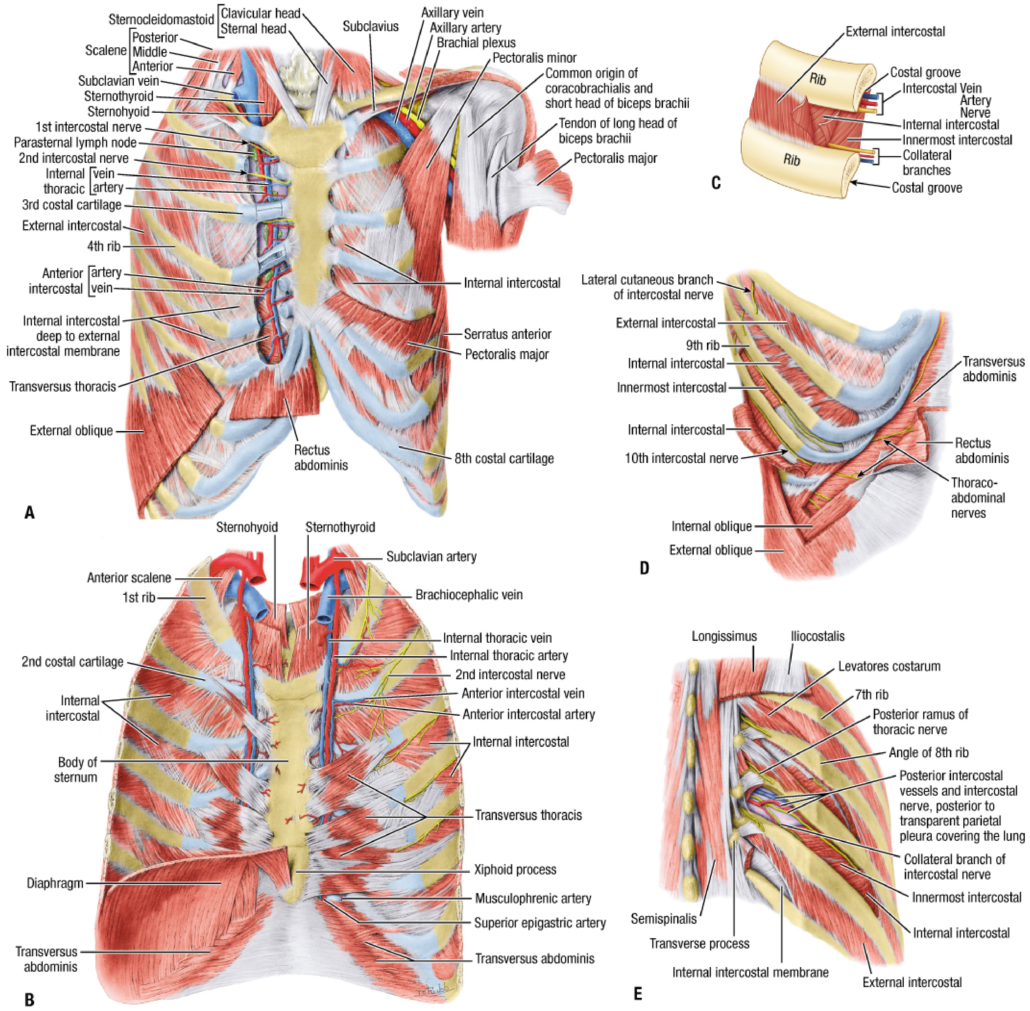
EXTRINSIC MUSCLES - The Big Surface Muscles
- Pectoralis major - the big chest muscle, from clavicle/sternum → humerus. Adducts and medially rotates the arm. In forced inspiration, helps expand the chest.
- Pectoralis minor - deep to pec major, from ribs 3-5 → coracoid process of scapula
- Serratus anterior - "the boxer's muscle," from upper 8 ribs → medial border of scapula. Protracts and rotates the scapula
- Trapezius - superficial, from skull/spine → clavicle and scapula spine
- Latissimus dorsi - from lower 6 thoracic vertebrae/iliac crest → humerus. Extends and adducts the arm. Important chest wall reconstruction flap!
- Rhomboids (major and minor)
- Serratus posterior (superior and inferior) - accessory respiratory muscles
- Erector spinae (deep paraspinal group)
🩸 Part 3: Neurovascular Bundle - The VAN in the Groove
Mnemonic: VAN from top to bottom in the costal groove
Vein - Artery - Nerve
- Intercostal Vein (highest)
- Intercostal Artery (middle)
- Intercostal Nerve (lowest)
🏥 Clinical Rule: Always pass needles (thoracentesis, chest tubes, nerve blocks) just above the upper border of the lower rib (i.e., lowest point of the intercostal space). This keeps you away from the VAN bundle hiding under the rib above.
Blood Supply of the Intercostal Space
| Source | Where from | Supplies |
|---|---|---|
| Posterior intercostal arteries | Descending thoracic aorta (for spaces 3-11); Supreme intercostal artery (for spaces 1-2) | Posterior 2/3 of each intercostal space |
| Anterior intercostal arteries | Internal thoracic artery (= internal mammary artery) → upper 6 spaces; Musculophrenic artery → lower spaces | Anterior 1/3 |
- Posterior → azygos vein (right) and hemiazygos (left) → SVC
- Anterior → internal thoracic veins → brachiocephalic veins
- Posterior chest wall → thoracic duct (left) / right lymphatic duct (right)
- Anterior → parasternal lymph nodes along the internal thoracic vessels
Intercostal Nerves
- Rami communicantes - connect to the sympathetic trunk
- Posterior cutaneous branch - to skin of the back
- Lateral cutaneous branch - exits mid-axillary line, supplies the side of the trunk
- Anterior cutaneous branch - reaches the front of the chest/abdomen
- Intercostal muscles
- Parietal pleura and peritoneum (hence, rib fractures cause pleuritic pain)
- Skin of the chest and abdomen (segmental dermatomes T1-T11)
🧠 Dermatome landmarks to memorize:
- T4 = nipple
- T10 = umbilicus
- T12 = inguinal ligament
🔲 Part 4: Thoracic Apertures (Inlets & Outlet)
- Bounded by: T1 vertebra (behind), 1st rib (sides), manubrium (front)
- Contents passing through: trachea, esophagus, great vessels (aorta, SVC), thoracic duct, sympathetic chain
- Tilted anteriorly at ~15° (faces upward and forward)
- Bounded by: T12 vertebra (behind), ribs 7-12 and costal margin (sides), xiphoid (front)
- Closed by the diaphragm
- Three major structures pierce the diaphragm:
- Vena cava at T8 (in the central tendon)
- Esophagus at T10 (with vagus nerves)
- Aorta at T12 (with thoracic duct)
- Mnemonic: I 8 (ate) 10 eggs At 12 = IVC-T8, Esophagus-T10, Aorta-T12
📋 Quick Summary Table
| Structure | Key Details |
|---|---|
| True ribs | 1-7, directly to sternum |
| False ribs | 8-10, via cartilage of rib above |
| Floating ribs | 11-12, no sternal connection |
| Sternal angle (Louis) | Manubrium-body junction; rib 2; T4/T5; carina |
| Typical rib parts | Head → Neck → Tubercle → Angle → Shaft → Costal cartilage |
| Costal groove | Inferior surface of rib; contains VAN (Vein, Artery, Nerve) |
| Intercostal muscles | External (outermost) → Internal (middle) → Innermost (deepest) |
| VAN order | Vein top, Artery middle, Nerve lowest - under each rib |
| Safe needle entry | Just above the upper border of the lower rib |
| Posterior blood supply | Descending thoracic aorta (spaces 3-11) |
| Anterior blood supply | Internal thoracic (mammary) artery |
| Venous drainage | Azygos (right) / Hemiazygos (left) posteriorly |
| IVC through diaphragm | T8 |
| Esophagus through diaphragm | T10 |
| Aorta through diaphragm | T12 |