
Importance of external and internal tooth structures during cavity preparation . For 50 marks university exam answer . Give me from contents to refernces . And also diagrams wherever necessary
Quick answer
Importance of External and Internal Tooth Structures During Cavity Preparation
Contents
- Introduction
- Definition of Cavity Preparation
- External Tooth Structures – Description and Importance
- Internal Tooth Structures – Description and Importance
- Clinical Significance of Understanding Tooth Structure in Cavity Preparation
- Principles of Cavity Preparation Related to Tooth Structure
- Diagrams
- Summary
- References
1. Introduction
2. Definition of Cavity Preparation
3. External Tooth Structures – Description and Importance
A. Enamel
- Hardest, most mineralized tissue in the human body (96% inorganic hydroxyapatite).
- Arranged in enamel rods/prisms running from the dentino-enamel junction (DEJ) to the tooth surface.
- Importance in cavity preparation:
- Enamel rod direction dictates the direction of the bevel and cavosurface margin angle; cutting must follow rod orientation to avoid creating unsupported enamel rods that fracture under masticatory load.
- Since enamel is brittle and has no reparative capacity, preparation design must avoid leaving thin, unsupported margins.
- Determines cavosurface angle (ideally 90 degrees for amalgam to prevent marginal fracture; beveled margins for enamel-bonded composite to increase surface area for etching and bonding).
- Its thickness varies (thickest at cusp tips, thinnest at cervical third and cementoenamel junction) - guiding depth of preparation to prevent perforation.
B. Cementum
- Covers the root surface, thinner and softer than enamel, has some cellular regenerative capacity (cellular cementum at apex).
- Importance:
- In root caries or cervical cavity preparation, cementum's softness and thinness demand a gentler preparation approach to avoid iatrogenic damage or exposing dentin/pulp.
- Because cementum lacks the hardness of enamel, cavosurface margins on cementum require modified bevel designs and different finishing burs.
C. External Tooth Contours and Anatomy (Cusps, Ridges, Fossae, Fissures, Grooves, Contact Areas, Line Angles, Point Angles)
- Importance:
- Occlusal anatomy (fissure pattern, cusp height, marginal ridges) determines the outline form of Class I and Class II preparations; the outline must follow natural fissure patterns to avoid weakening the tooth or leaving caries-susceptible enamel behind.
- Line angles and point angles must be rounded internally to reduce stress concentration and prevent restoration or tooth fracture.
- Understanding proximal contours and contact areas is essential for correct proximal box design in Class II/III/IV preparations, ensuring proper contact, embrasure form, and food deflection to protect the interdental papilla.
- Cervical convexity (cementoenamel junction curvature) guides gingival margin placement to avoid gingival trauma or overhang.
4. Internal Tooth Structures – Description and Importance
A. Dentin
- Comprises the bulk of the tooth; less mineralized (70% inorganic) and more resilient/elastic than enamel; contains dentinal tubules radiating from the pulp to the DEJ.
- Importance in cavity preparation:
- Provides support to the overlying enamel - loss of dentin support ("unsupported enamel") is a key reason for extending or modifying a cavity outline.
- Dentin's elasticity absorbs occlusal stresses, but if too much is removed the enamel loses its foundation and fractures.
- Because dentinal tubules connect directly to the pulp, cutting dentin risks pulpal irritation, hence the need for a "no-pressure, light intermittent cutting, adequate coolant" technique.
- Depth of preparation into dentin is calculated relative to the DEJ and pulp horns to avoid pulp exposure - direct relevance to the concept of "safe zones" in cavity depth (e.g., axial wall depth of 0.2 to 0.5 mm into dentin beyond the DEJ).
- Secondary and tertiary (reparative) dentin formation in response to caries or trauma must be recognized during excavation, since it indicates pulpal defense and is usually retained rather than aggressively removed.
B. Dentino-Enamel Junction (DEJ)
- Scalloped junction between enamel and dentin.
- Importance:
- Acts as a stress-distributing junction, preventing crack propagation from enamel into dentin.
- Caries tends to spread laterally along the DEJ - cavity preparation must extend to remove all caries at this junction even if the external enamel lesion appears small, otherwise recurrent caries results.
C. Pulp (Pulp Chamber, Pulp Horns, Root Canals)
- Neurovascular connective tissue at the core of the tooth, varying in size and position with age (recession with age, prominent pulp horns in young teeth).
- Importance:
- Pulp horn position (particularly under cusps) is a critical landmark determining safe axial and pulpal wall depths - inadvertent exposure requires additional treatment (pulp capping, root canal therapy) and worsens prognosis.
- Pulp size decreases with age due to secondary dentin deposition, meaning preparations in younger patients require more conservative depths than in older patients.
- Vascularity and innervation of the pulp make thermal, mechanical, and chemical protection (e.g., use of cavity liners/bases, avoiding desiccation, minimizing heat generation) essential to preserve pulp vitality.
D. Root Structure and Root Canal System
- Importance: Relevant in preparation of cervical and root caries lesions and in preparations related to endodontically treated teeth; root morphology influences retention design in extensive restorations (e.g., pins, posts).
5. Clinical Significance of Understanding Tooth Structure in Cavity Preparation
- Preservation of tooth strength: Knowledge of enamel rod direction and dentin support prevents unnecessary weakening of cusps and marginal ridges.
- Pulp protection: Awareness of pulp horn location and dentin thickness prevents accidental exposure and postoperative sensitivity.
- Retention and resistance form: Internal structures (dentin, pulpal and axial walls) provide the mechanical basis for retention grooves, slots, and undercuts (in amalgam) or for adhesive bonding surface area (in composites).
- Marginal integrity: External enamel rod orientation determines cavosurface margin design to prevent enamel fracture and microleakage.
- Biologic width/gingival health: Understanding cementum and cervical anatomy prevents gingival and periodontal damage.
- Esthetics: Preservation of the natural external tooth form and translucency of enamel guides minimally invasive and esthetic cavity designs, especially in anterior teeth.
- Prevention of recurrent caries: Extension to sound tissue at the DEJ and along fissures (extension for prevention, GV Black's principle) relies on understanding how caries spreads internally versus its external presentation.
6. Principles of Cavity Preparation Related to Tooth Structure (G.V. Black's Principles)
- Outline form: dictated by external anatomy (fissures, caries extent, esthetic zone).
- Resistance form: dictated by internal dentin bulk and pulp chamber position - preserves tooth and restoration against fracture.
- Retention form: mechanical features cut into dentin (grooves, undercuts) or bonding to enamel/dentin surfaces.
- Convenience form: access shape aligned with internal pulp anatomy and external tooth position.
- Removal of remaining caries and pulp protection: based on depth of dentin caries relative to pulp.
- Finishing of enamel walls and margins: based on enamel rod direction (external structure).
- Toilet of the cavity: cleaning without further compromising exposed internal structures.
7. Diagrams (to include in the written exam answer)
- Longitudinal section of a tooth showing enamel, dentin, pulp chamber, pulp horns, DEJ, cementum, and root canal.
- Enamel rod orientation diagram showing rods running perpendicular to the DEJ and how cavosurface angle relates to rod direction (showing "unsupported enamel rods" vs "supported enamel rods").
- Cross-section of a Class I/Class II cavity preparation labeling pulpal wall, axial wall, gingival wall, line angles, point angles, and cavosurface margin.
- Diagram showing "extension for prevention" along developmental fissures.
8. Summary
9. References
- Sturdevant's Art and Science of Operative Dentistry, 6th Edition - Roberson, Heymann, Swift.
- Fundamentals of Operative Dentistry: A Contemporary Approach - Summitt, Robbins, Hilton, Schwartz.
- G.V. Black's Principles of Cavity Preparation - Operative Dentistry Classical Texts.
- Ten Cate's Oral Histology: Development, Structure, and Function - Nanci A.
- Orban's Oral Histology and Embryology.
- Textbook of Operative Dentistry - Nisha Garg, Amit Garg.
Not satisfied please eloborate and give me images also
longitudinal section of tooth showing enamel dentin pulp cementum labeled diagram
enamel rod orientation dentinoenamel junction diagram
Class I Class II cavity preparation cross section walls line angles diagram
tooth anatomy
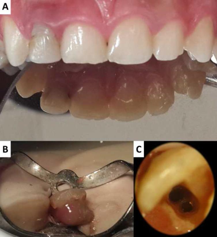
This composite intraoral image sequence documents an endodontic retreatment of the maxillary right lateral incisor (tooth #12). Image A presents a clinical facial view and a palatal mirror reflection of the anterior teeth, showing cervical discoloration, a mesial carious lesion, and a palatal composite restoration on tooth #12. Image B depicts the tooth under rubber dam isolation during endodontic access; it demonstrates purulent exudate (pus discharge) emerging from the access cavity following the removal of failing gutta-percha filling material, indicating symptomatic apical periodontitis. Image C provides a high-magnification view through a dental operating microscope, revealing the internal anatomy of the pulp chamber. The magnification highlights the presence of two distinct root canals—a labial canal and a palatal canal—which is an anatomical variation for this tooth type. The sequence illustrates the clinical presentation, infectious complications, and microscopic identification of missed canal anatomy during endodontic therapy.
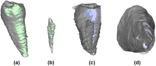
This diagnostic image set displays a 3D reconstruction of a human incisor tooth and its internal endodontic anatomy, derived from micro-CT or cone-beam CT (CBCT) data. The visual is divided into four panels: (a) provides a whole-tooth view showing the conical morphology of the incisor with a textured enamel surface and vertical striations; (b) isolated 3D segmentation of the root canal, demonstrating its slender, tapered trajectory; (c) a longitudinal sectional view where the outer dentin/enamel is partially removed to reveal the spatial relationship of the root canal within the tooth structure; and (d) a transverse cross-sectional view illustrating the circular-to-ovoid shape of the root canal at a specific cervical or mid-root level. The educational focus is on dental anatomy and endodontic modeling, highlighting the use of advanced imaging to map internal cavities for diagnostic or procedural planning. The color-coded mesh surfaces distinguish the external tooth (gray/green) from the internal pulp space (blue/white).
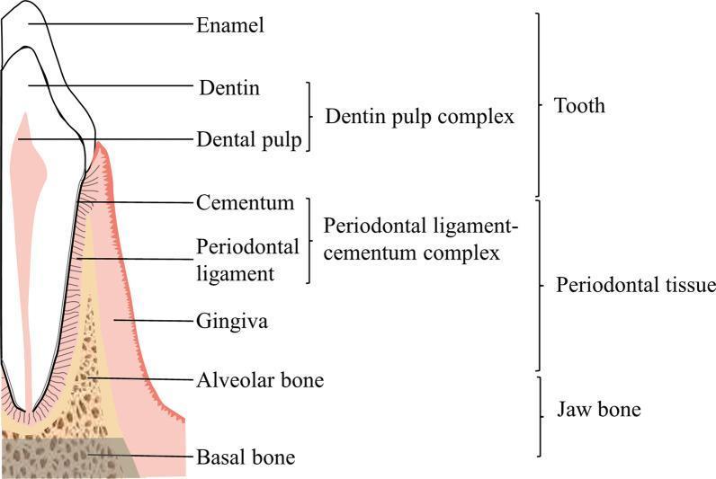
An anatomical diagram illustrating the structural composition of the human tooth and its surrounding supportive tissues within the jaw bone. The schematic is divided into three primary categories: Tooth, Periodontal Tissue, and Jaw Bone. The 'Tooth' section identifies the enamel, dentin, and dental pulp, noting that the latter two constitute the 'dentin pulp complex'. The 'Periodontal tissue' encompasses the gingiva, alveolar bone, and the 'periodontal ligament-cementum complex,' which consists of the cementum and the periodontal ligament fibers that anchor the tooth root. Finally, the 'Jaw bone' is differentiated into two layers: the porous alveolar bone, which immediately supports the tooth sockets, and the denser, underlying basal bone. This medical illustration serves as an educational tool for dental anatomy and periodontology, emphasizing the functional relationship between the hard tissues of the tooth and the supporting periodontal apparatus.
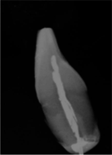
This diagnostic radiograph displays a longitudinal view of a human tooth, likely an incisor or canine, undergoing endodontic evaluation. The image illustrates the internal anatomy of the tooth, including the enamel, dentin, and a centrally located, radio-opaque material extending through the pulp chamber and into the root canal system. This dense material signifies a root canal filling or the presence of an experimental probe, such as a thermocouple used for intrapulpal temperature monitoring. The coronal portion shows a wider radiopacity where the instrument enters the pulp chamber, tapering towards the apex. Notably, the root apex appears blunted or resected, consistent with an apicoectomy or experimental preparation. The contrast between the natural tooth structure and the endodontic material provides a clear visualization of canal morphology and instrument placement. This image is relevant for dental education regarding endodontic procedures, pulp chamber anatomy, and clinical research methodologies in restorative dentistry.
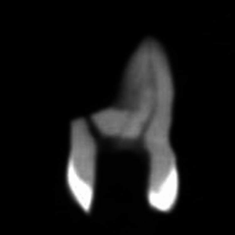
This diagnostic image shows a single-plane slice from a Cone-Beam Computed Tomography (CBCT) scan of a maxillary molar tooth, specifically oriented to evaluate the mesiobuccal root canal system. The visual depicts the tooth crown and two root extensions against a dark, low-density background. There is a clear gradient of radiopacity: the crown and pulp chamber area appear moderately radiopaque (mid-gray), while the apical regions of the roots exhibit high radiopacity (bright white), suggesting a focus on endodontic landmarks or the presence of dense tissue/materials at the apex. The image illustrates the internal anatomy of the tooth, including the transition from the coronal pulp chamber to the cervical and middle thirds of the root. Clinically, this CBCT slice is used in endodontics for lateral canal evaluation, identifying canal morphology based on Vertucci’s classification, and assessing apical anatomy for treatment planning or research into root canal complexities.
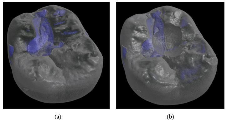
This diagnostic image consists of two reconstructed 3D micro-computed tomography (µCT) scans of a human molar tooth restoration, demonstrating mechanical wear and abrasion. The scans compare the tooth at baseline (a) and after a chewing simulation of 1,200,000 cycles (b). The images utilize a grayscale rendering for the tooth anatomy and dental restorative material, with blue color-coding identifying specific regions of interest or material surface irregularities. In image (a), the occlusal surface exhibits intact morphology with defined cusps and a relatively smooth central fissure. In image (b), significant occlusal wear is visible, characterized by a distinct central depression, loss of material volume, and blunting of the cuspal anatomy. The blue highlighted regions show an altered distribution post-simulation, indicating changes in surface texture and exposure of deeper material layers due to cyclic loading. This comparison is used in dental materials science to quantitatively assess the wear resistance and volumetric stability of restorative materials like DeltaFil.
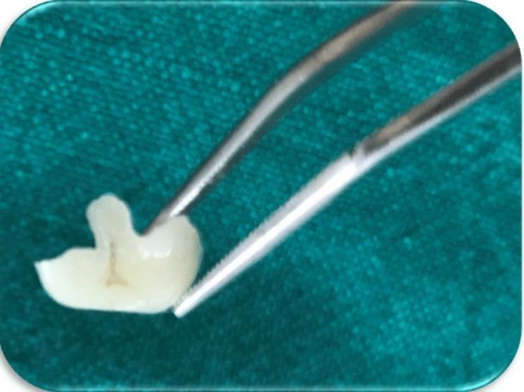
A procedural photograph from a dental laboratory perspective showing a custom-fabricated ceramic onlay for tooth 16. The tooth-colored restoration is held by metallic dental forceps against a blue-green background. The onlay displays complex occlusal morphology, including anatomically contoured cusp-like projections and defined grooves to mimic natural posterior tooth anatomy. The ceramic material exhibits high translucency and a polished, smooth surface texture. The margins appear thin, well-defined, and precisely finished to ensure an accurate fit for the prepared cavity. This image illustrates an indirect aesthetic restoration designed to manage extensive cuspal fractures and caries in conservative dentistry.
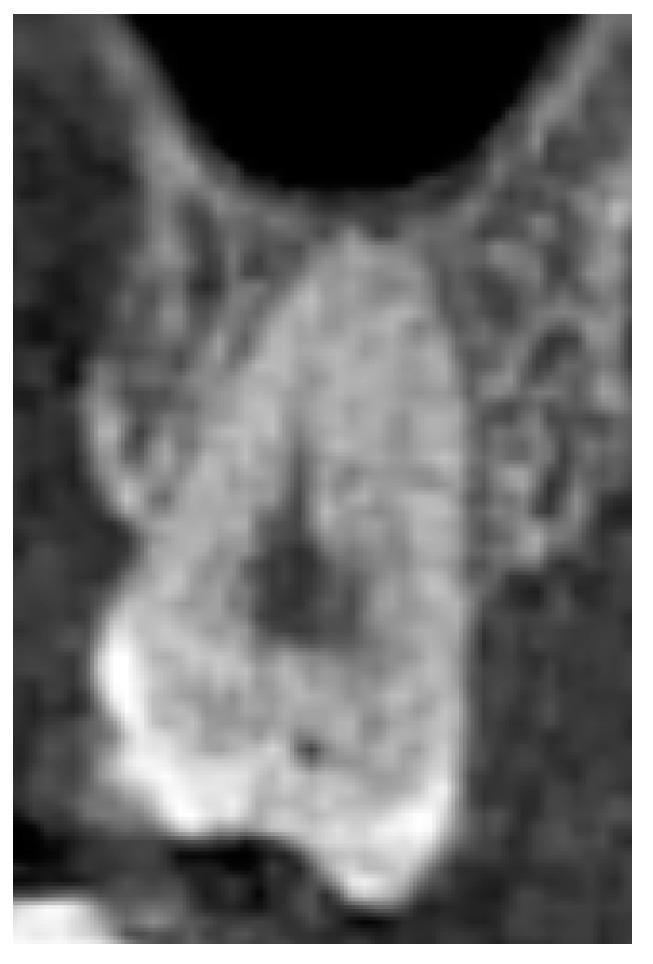
This diagnostic image is a Cone Beam Computed Tomography (CBCT) cross-sectional view of a single human maxillary tooth, used to demonstrate normal dental anatomy. The tooth is positioned within the alveolar bone and exhibits well-defined structural components, including radiopaque enamel and dentin layers. The internal radiolucency represents the healthy pulp chamber and root canal system. There is no evidence of dental caries, periapical radiolucency, or significant periodontal bone loss, with the alveolar crest maintaining a physiological distance from the cementoenamel junction (CEJ). The surrounding trabecular bone displays uniform density. Superior to the tooth, a portion of the maxillary sinus floor is visible, showing a normal relationship between the root apex and the sinus cavity. This visual serves as a reference for a 'healthy tooth' classification in dental and endodontic assessment, emphasizing the absence of pathology in the tooth's hard tissues and supporting structures.
enamel prisms histology
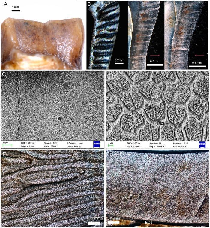
This composite educational graphic details the enamel microstructure of a molar via light microscopy and scanning electron microscopy (SEM). Panel A shows a clinical photograph of a tooth crown. Panels B and C demonstrate vertical Hunter-Schreger Bands (HSB) under polarized light and SEM, highlighting the distinct arrangement of diazones (d), parazones (p), and transitional zones (t). Panel D (5000x magnification) provides a high-resolution view of enamel prisms (P) in cross-section, showing rounded to oval morphologies surrounded by the interprismatic matrix (IPM) and occasional irregular seams (S). Panel E displays a tangential section showing bifurcated bands, where parazone prisms appear elongated and bright compared to the dark, rounded diazone prisms. Panel F illustrates the Schmelzmuster in a vertical section, measuring approximately 0.6 mm in thickness, with HSB inclined at 20 degrees relative to the enamel-dentine junction (EDJ). Radial enamel layers (50m) are visible near both the EDJ and the outer enamel surface. This visual aid is intended for advanced dental histology and evolutionary biology studies focusing on tooth mineralization and structural patterns.
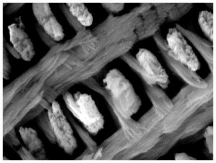
This diagnostic image is a high-magnification scanning electron micrograph (SEM) showing the microarchitecture of dental enamel. The content type is a Diagnostic Image focused on Histology and Odontology. The image depicts a complex, highly organized structural arrangement of biological apatite. Bright, distinct, and somewhat granular columnar structures, representing hydroxyapatite prisms, are seen arranged in semi-parallel arrays. These are interwoven with a finer, darker filamentous network that appears more fibrous and wispy. This network corresponds to the proteinaceous matrix, primarily involving amelogenin and polyproline-repeat elements, which guides the alignment and growth of the mineral crystals during amelogenesis. The visual highlights the relationship between the solid mineral components and the organic scaffolding that dictates the durability and functional properties of mammalian tooth enamel. Key educational concepts include the structural organization of hydroxyapatite, the role of ameloblasts in enamel formation, and the transition from protein-guided nanospheres to mature crystalline prisms.
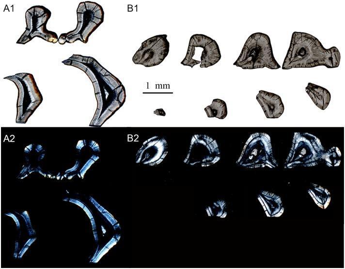
This diagnostic comparison image displays transverse sections of tooth molars (m1 and m2) from the species Lambdopsalis bulla, highlighting the enamel microstructure (Schmelzmuster). The composite consists of four panels: A1 and B1 show optic images under ordinary light, while A2 and B2 provide polarized light images of the same sections. The optic images (A1, B1) reveal arcade-shaped enamel prisms with visible prism sheaths forming three-quarters of a circle and slender prism seams. Reddish pigmentation is visible on the outer enamel crown, especially in the m2 section (A1). Polarized light images (A2, B2) emphasize birefringence patterns that indicate variations in crystallite orientation. Bright bands in A2 highlight the arcade structure and delimit crystallite bundles, making the enamel-dentine junction (EDJ) more distinct than in the optic views. These images demonstrate the radial packing of gigantoprismatic enamel and the transition from prismatic inner zones to an outer aprismatic enamel layer, serving as an educational resource for comparative dental histology and odontological evolution.

This diagnostic image is a polarized light microscopy micrograph of a 200 µm thick longitudinal tooth section, specifically a permanent premolar used in a remineralization study. The image demonstrates the birefringence of dental hard tissues, likely enamel or superficial dentin, showing a characteristic striated texture with parallel linear features that correspond to the orientation of enamel prisms or dentin tubules. The section exhibits vibrant color variations ranging from blues and greens to yellows and oranges, reflecting differences in mineral density and crystalline structural organization. A distinct surface lesion is visible, where the outer border shows a bright, thin refractive band indicating a change in mineral composition at the interface with the surrounding environment. The image is used to assess lesion depth and the efficacy of SHY-NM remineralizing agents in treating demineralized dental tissue. It highlights the transition between sound and remineralized tissue, providing clinical insight into dental histology and preventive dentistry.
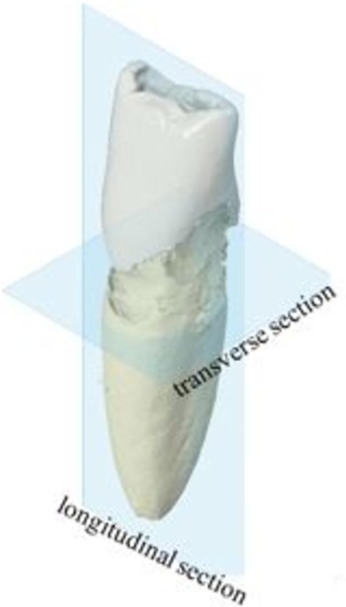
cavity preparation cavosurface angle line angle point angle diagram operative dentistry
"minimally invasive dentistry" AND "cavity preparation"
(University Exam Answer – 50 Marks, Fully Illustrated)
Contents
- Introduction
- Definition and Objectives of Cavity Preparation
- Overview of Tooth Structure (External and Internal)
- External Tooth Structures and Their Importance in Cavity Preparation
- Internal Tooth Structures and Their Importance in Cavity Preparation
- Integration – External and Internal Walls of a Prepared Cavity
- G.V. Black's Principles of Cavity Preparation Linked to Tooth Structure
- Clinical Consequences of Ignoring Tooth Structure
- Recent Evidence – Minimally Invasive Trends
- Diagrams
- Summary
- References
1. Introduction
2. Definition and Objectives of Cavity Preparation
- Complete removal of caries/pathology.
- Maximum conservation of sound tooth structure.
- Protection of the pulp.
- Creation of a form that allows retention and resistance of the restoration.
- Restoration of function, contour, and esthetics.
3. Overview of Tooth Structure (External and Internal)
| Tissue | Location | Character |
|---|---|---|
| Enamel | External, covers crown | Hardest tissue, acellular, non-vital |
| Cementum | External, covers root | Bone-like, thin, vital at surface |
| Dentin | Internal, bulk of tooth | Elastic, tubular, vital (via odontoblast processes) |
| Pulp | Innermost, core | Living connective tissue, nerves, vessels |
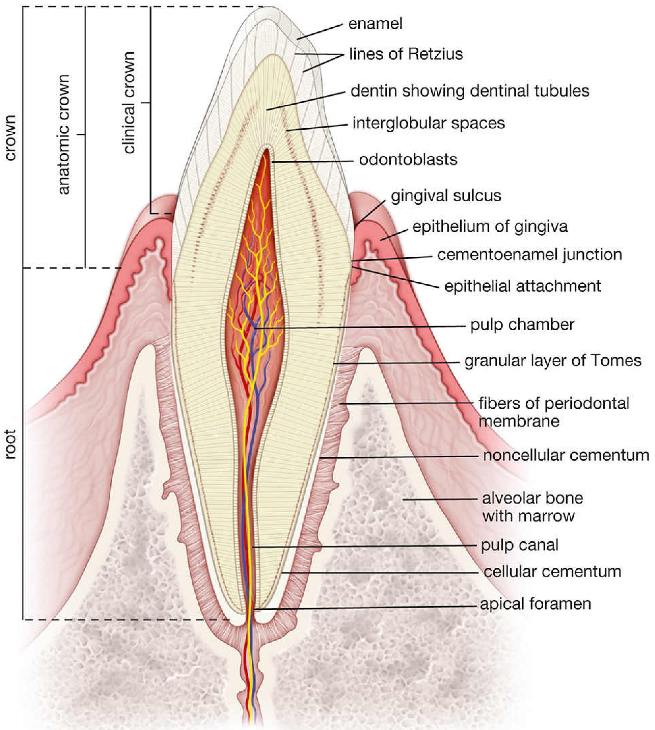
4. External Tooth Structures and Their Importance in Cavity Preparation
A. Enamel
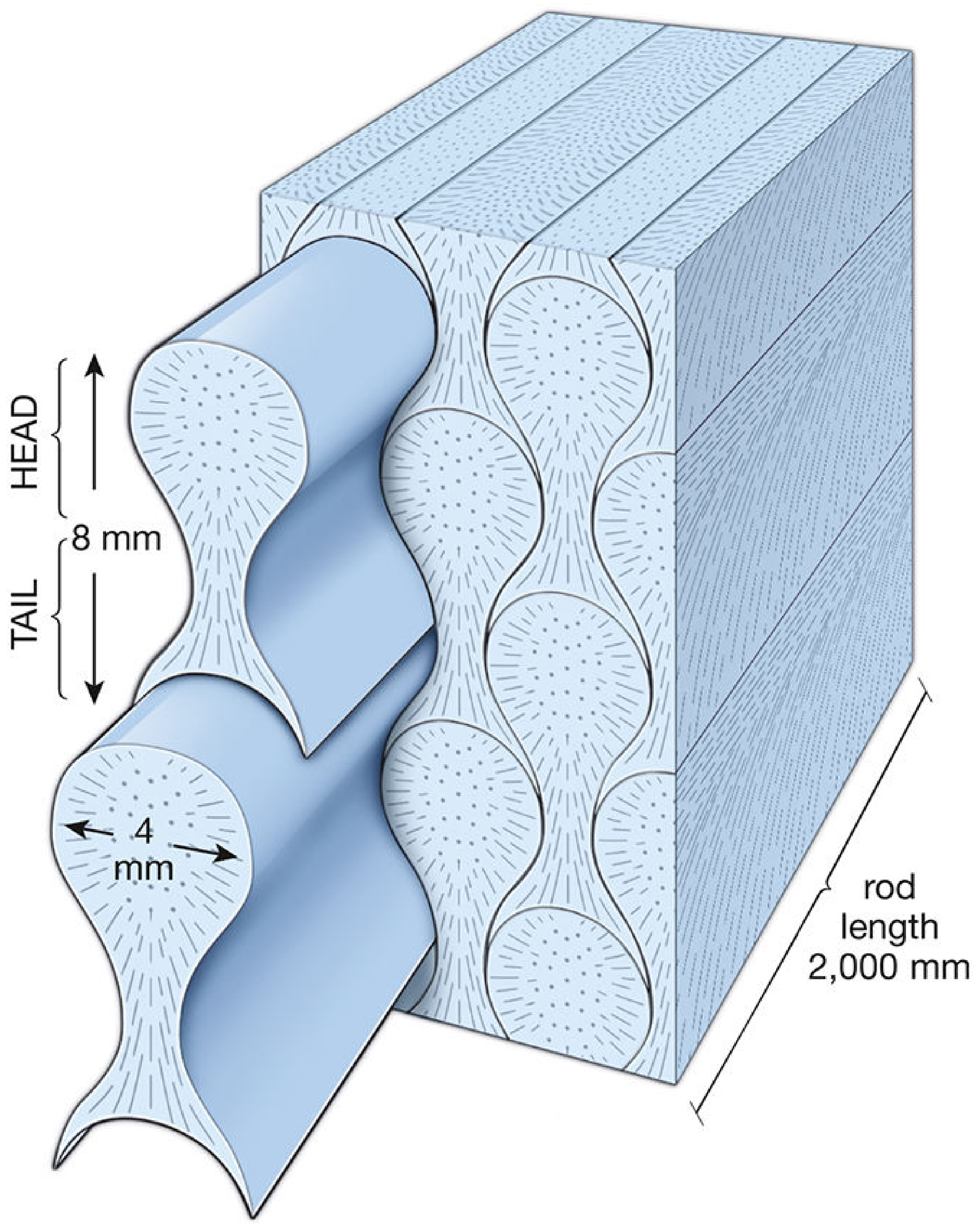
- Cavosurface margin design must follow the direction of the enamel rods. If a margin is cut so that rods are left unsupported by underlying dentin, they fracture under occlusal load, opening a gap for microleakage and recurrent caries.
- Cavosurface angle: for amalgam (a non-adhesive, brittle material) a 90° butt-joint margin is required so the amalgam and enamel margins are both strong; for bonded composite, a bevelled margin increases surface area of enamel rods exposed for acid-etching and bonding.
- Enamel thickness varies (thickest ~2.5 mm at cusp tips, thinnest at the cervical third), so the depth to which a bur is taken occlusally versus cervically must differ to avoid needless removal or perforation.
- Enamel is acellular and avascular - once cut, it cannot repair itself, reinforcing the principle of "minimal but complete" removal.
- Prism direction also explains why caries in enamel spreads in a cone with the base towards the DEJ - the outline of the external cavity must therefore be planned wider at the DEJ level than the visible surface lesion suggests.
B. Cementum
- In cervical/root caries the softness of cementum means preparation must be done with lighter, slower cutting to avoid gouging or over-instrumentation.
- Since cementum lacks the hardness of enamel, the cavosurface bevel and finishing bur selection must be modified compared with enamel margins.
- Cementum's thinness near the cementoenamel junction (CEJ) increases risk of iatrogenic exposure of underlying dentin/pulp if the gingival margin of a Class II or Class V cavity is placed carelessly.
C. External Anatomic Contours (Cusps, Fossae, Fissures, Grooves, Marginal Ridges, Contact Areas, Line/Point Angles)
- Occlusal fissure pattern dictates the outline form of Class I preparations - the cavity margin should follow the fissure pattern, including the principle of "extension for prevention," to avoid leaving caries-prone enamel behind while conserving marginal ridges and cusps.
- Contact areas and proximal contours guide the design of the proximal box in Class II/III/IV cavities, ensuring correct emergence profile, embrasure form, and protection of the interdental papilla from food impaction.
- External line angles and point angles, once transferred internally as the junctions of cavity walls, must be rounded to avoid stress concentration (see Section 6).
5. Internal Tooth Structures and Their Importance in Cavity Preparation
A. Dentin
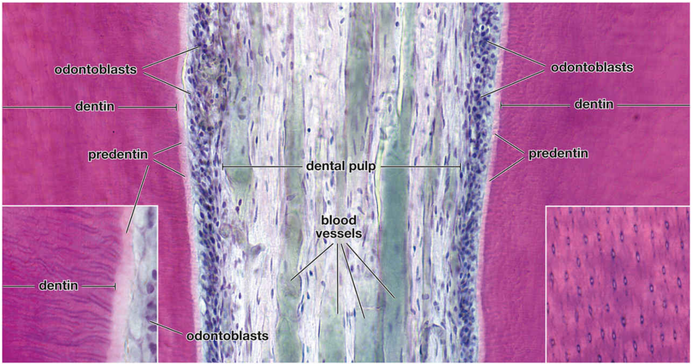
- Support of enamel - dentin is the foundation on which enamel rests; removal of carious dentin beneath sound-looking enamel, if excessive, leaves "unsupported enamel" that must then be sacrificed, altering the whole outline form.
- Sensory/vital connection to pulp - because odontoblast processes run continuously from the DEJ to the pulp inside dentinal tubules, any cutting, desiccation, heat, or chemical insult to dentin is transmitted directly to the pulp (hydrodynamic theory of dentinal sensitivity), mandating water-cooled, intermittent, sharp-bur cutting technique.
- Depth control - the operator calculates safe axial and pulpal wall depths relative to the DEJ (usually only 0.2-0.5 mm into dentin at the axial wall, and about 0.5 mm into dentin at the pulpal floor) to avoid pulp exposure, as shown in Fig. 6.
- Reparative capacity - unlike enamel, dentin can lay down tertiary (reparative) dentin in response to a slow carious insult; this must be recognised (harder, more discoloured dentin near the pulp) and conservatively left in place rather than aggressively excavated, protecting the pulp.
- Retention - since dentin is more workable than enamel, retention grooves, coves, and slots for amalgam are cut into dentin, and it is also the principal bonding substrate for adhesive resin restorations (though bonding to dentin is technically more demanding due to its tubular, wet, organic nature).
B. Dentino-Enamel Junction (DEJ)
- It acts as a shock absorber, dissipating occlusal stress and arresting the propagation of enamel micro-cracks into dentin.
- Caries spreads laterally along the DEJ faster than through enamel itself, producing a lesion that undermines a much wider area of enamel than is visible from the surface. The internal extension of the cavity at this level, therefore, is always wider than the external entry point - a key reason why "the external lesion always underestimates the internal spread."
C. Pulp (Pulp Chamber, Pulp Horns, Root Canal System)
- Pulp horn position is a critical landmark that limits how deep a bur can safely go under a cusp; ignoring it risks mechanical pulp exposure.
- With age, secondary dentin deposition recedes the pulp, meaning cavity depths that are safe in an older patient may expose the pulp in a young patient with large pulp horns - age-based modification of preparation depth is essential.
- Vital pulp tissue must be protected from thermal trauma (bur speed/heat), desiccation, and toxic materials - this underlies the use of cavity liners, bases, and pulp-protective agents whenever dentin thickness remaining over the pulp is judged inadequate.
- Any breach of the pulp changes the entire treatment plan (from a simple restoration to pulp capping or root canal therapy), directly affecting prognosis - underscoring why pulp anatomy must be pictured mentally during every preparation step.
D. Root Dentin and Root Canal System
6. Integration - External and Internal Walls of a Prepared Cavity

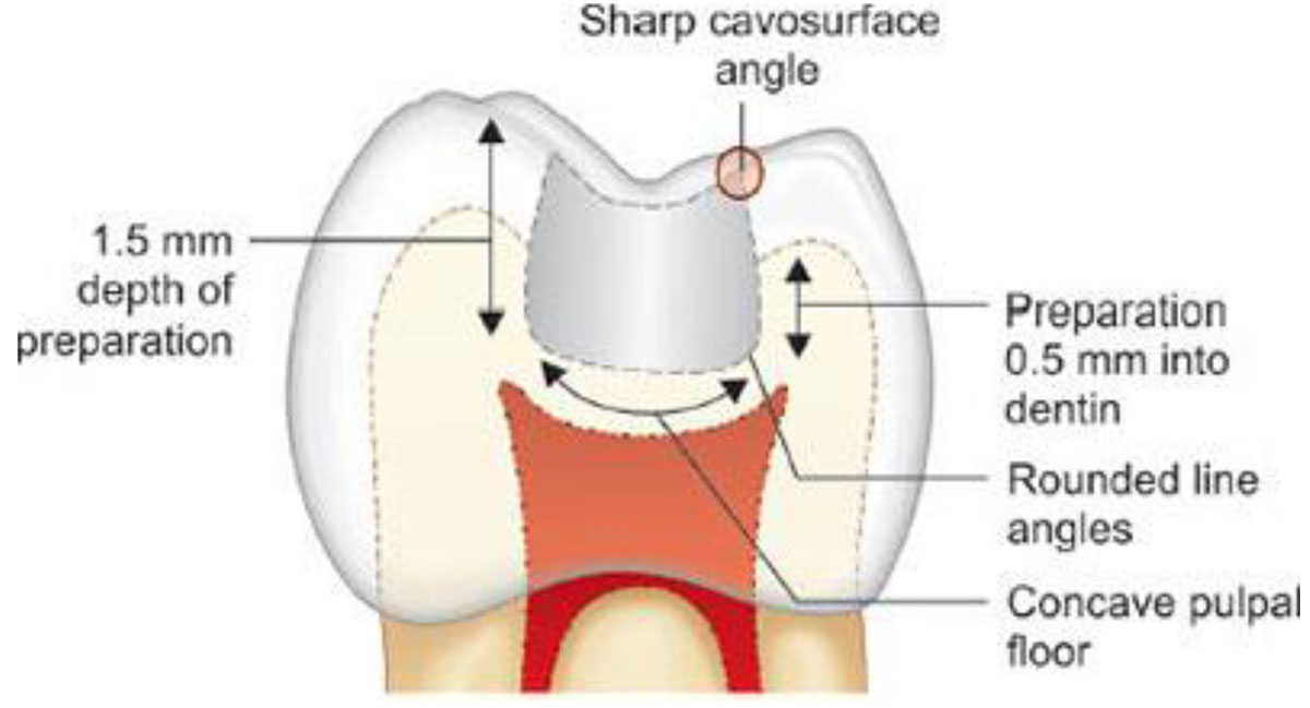
- Pulpal wall / floor - cut in dentin, parallel to the external occlusal plane, following the natural convexity of the pulp roof; kept as shallow as safely possible.
- Axial wall - cut in dentin on the proximal aspect, following the natural external convexity of the root/crown surface, at a set distance from the DEJ (not from the external surface), since DEJ position varies with enamel thickness.
- Cavosurface margin - the actual junction between the internal prepared wall and the external, unprepared tooth surface; its angulation is dictated by enamel rod direction (external) and choice of restorative material.
- Line and point angles - internal angles formed where two or three walls meet; these are rounded (never left as sharp internal angles) because sharp internal angles concentrate mechanical stress in the underlying dentin and can initiate fracture lines or a crack toward the pulp.
7. G.V. Black's Principles of Cavity Preparation Linked to Tooth Structure
| Principle | Structure it depends on |
|---|---|
| Outline form | External enamel anatomy - fissures, caries extent, esthetic zone |
| Resistance form | Internal dentin bulk, pulp chamber position, wall angles |
| Retention form | Dentin (grooves/undercuts) or enamel/dentin surface for bonding |
| Convenience form | Internal pulp anatomy and external tooth position/access |
| Removal of remaining caries | Depth of dentin caries relative to DEJ and pulp |
| Finishing of enamel walls | External enamel rod direction |
| Toilet of the cavity | Cleaning without further damaging exposed internal structures |
8. Clinical Consequences of Ignoring Tooth Structure
- Pulp exposure and postoperative pain - from ignoring pulp horn position/dentin thickness.
- Enamel fracture at margins - from cutting against rod direction or leaving unsupported enamel.
- Recurrent (secondary) caries - from underestimating lateral caries spread at the DEJ.
- Microleakage - from incorrect cavosurface angle for the chosen material.
- Tooth/restoration fracture - from sharp internal line angles concentrating stress, or from over-extension weakening cusps and marginal ridges.
- Gingival/periodontal injury - from disregard of the CEJ and thin cervical cementum.
9. Recent Evidence - Minimally Invasive Trends
- A 2025 systematic review and meta-analysis on microinvasive interventions for proximal caries (Tasleem et al., BMC Oral Health, PMID: 39780151) supports minimally invasive, tissue-conserving approaches over traditional extensive cavity preparation for early proximal lesions.
- A 2024 comparative meta-analysis of minimally invasive versus conventional caries removal in permanent dentition (González-Gil et al., Medicina, PMID: 38541128) found comparable success with greater tissue conservation using minimally invasive techniques.
10. Diagrams (Recommended for Full Marks - Draw/Label in Exam)
- Longitudinal section of a tooth: enamel, dentin, pulp (chamber + horns), cementum, DEJ, root canal (Fig. 1).
- Enamel rod orientation and keyhole cross-section, showing rod direction relative to cavosurface angle (Fig. 2).
- Dentin-pulp complex with odontoblasts and dentinal tubules (Fig. 3).
- Prepared cavity showing external walls vs internal walls (Fig. 4).
- Cavity depth diagram: 1.5 mm total depth, 0.5 mm into dentin, rounded line angles, concave pulpal floor (Fig. 5).
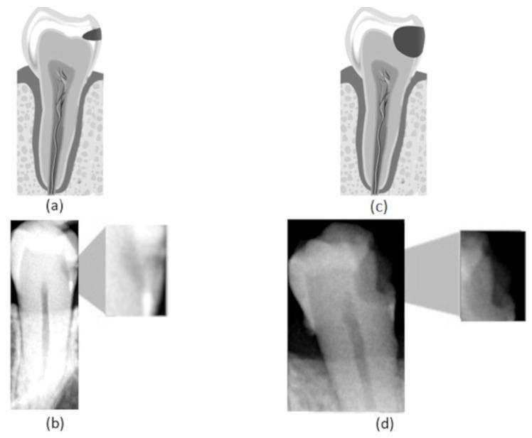
- Caries progression diagram: enamel-confined vs dentin-penetrating lesion (Fig. 6).
- "Extension for prevention" outline diagram along developmental fissures (draw freehand: occlusal surface with fissure pattern and cavity outline following it).
11. Summary
12. References
- Roberson TM, Heymann HO, Swift EJ. Sturdevant's Art and Science of Operative Dentistry, 6th ed. Elsevier/Mosby.
- Summitt JB, Robbins JW, Hilton TJ, Schwartz RS. Fundamentals of Operative Dentistry: A Contemporary Approach. Quintessence Publishing.
- Garg N, Garg A. Textbook of Operative Dentistry. Jaypee Brothers Medical Publishers.
- Ross MH, Pawlina W. Histology: A Text and Atlas with Correlated Cell and Molecular Biology, 8th ed - Chapter 16, "Digestive System I: Oral Cavity and Associated Structures," pp. 1437-1456.
- Mescher AL. Junqueira's Basic Histology: Text and Atlas, 17th ed - "Oral Cavity" and "Enamel/Dentin" sections.
- Nanci A. Ten Cate's Oral Histology: Development, Structure, and Function. Elsevier.
- Tasleem R, Alqahtani SA, Abogazalah N. Microinvasive interventions in the management of proximal caries lesions in primary and permanent teeth - systematic review and meta-analysis. BMC Oral Health. 2025. PMID: 39780151.
- González-Gil D, Flores-Fraile J, Vera-Rodríguez V, et al. Comparative Meta-Analysis of Minimally Invasive and Conventional Approaches for Caries Removal in Permanent Dentition. Medicina (Kaunas). 2024;60(3):402. PMID: 38541128.
- Columbia University CCNMTL. Operative Dentistry: Class II Cavity Preparation (educational reference for cavosurface/line angle terminology).