
preparation of anaesthesia machine ,intubation kit , suction machine, anaesthesia drugs
anaesthesia machine components setup preparation
This clinical laboratory photograph illustrates the standardization of post space preparation in dental research using a precision milling machine. The setup features a Degussa F1 milling unit holding a dental model consisting of a maxillary arch with ivory-colored teeth and a pink gingival base. The model is secured onto a multi-axial adjustable platform, allowing for precise angulation and positioning. A high-speed drill head, mounted on a vertical support column, holds a #16 carbide round bur (44.5 mm height). The bur is shown in direct contact with the cervical/coronal portion of a specific tooth, simulating the vertical drilling required for uniform intracanal post space creation. Key visible components include the grooved base, the mechanical adjustment knobs for the milling arm, and the stable mounting of the specimen, which is essential for ensuring methodological consistency in endodontic and restorative dental studies. This procedure is critical for evaluating fracture resistance and the efficacy of different fiber post systems.
A clinical photograph depicting a biomechanical experimental setup for orthopedic research in a laboratory setting. The central component is a synthetic, gray-colored pelvic specimen (Sawbones model) securely mounted on a metallic support stand with a locking ball joint, allowing for precise angular positioning. An acetabular cup component is visible, integrated into the hip socket of the model. To the right, a Hexagon Metrology Romer Absolute Arm, a high-precision coordinate measuring machine (CMM), is positioned to collect three-dimensional spatial data and digitized anatomical landmarks. In the background, a fluoroscopy unit (C-arm) is aligned with the pelvis to generate radiological images. Labels indicate key components including the pelvis, locking ball joint, acetabular cup, Romer Arm, fluoroscopy unit, and the 'Joint Point' software interface on a monitor. This setup is utilized for validating surgical software and calculating anatomic inclination and anteversion angles by comparing 2D fluoroscopic imaging with gold-standard 3D physical measurements.
This clinical photograph illustrates the experimental setup for the biomechanical testing of a human cadaveric lower leg specimen. The apparatus is designed to simulate single-leg standing posture using a universal mechanical testing machine (Instron model). Key components include a loading head connected via a ball joint to a holding jig, which secures the proximal tibia and fibula. The ball joint ensures unconstrained natural rotational reaction during axial loading. The distal portion of the specimen, consisting of the foot and ankle, is positioned on a TexScan film sensor resting on a base plate to measure plantar pressure distribution and the center of force (COF). An external digitizer is visible, used for capturing kinematic data of ankle joint motion. Anatomically, the specimen shows the removal of skin and subcutaneous tissues around the ankle to reveal deeper structures while preserving the syndesmotic ligaments and tendons for functional analysis. This setup is typically used in orthopedic research to evaluate the effects of surgical procedures, such as supramalleolar osteotomy (SMO), on ankle joint mechanics.
endotracheal intubation equipment laryngoscope blade ETT tube
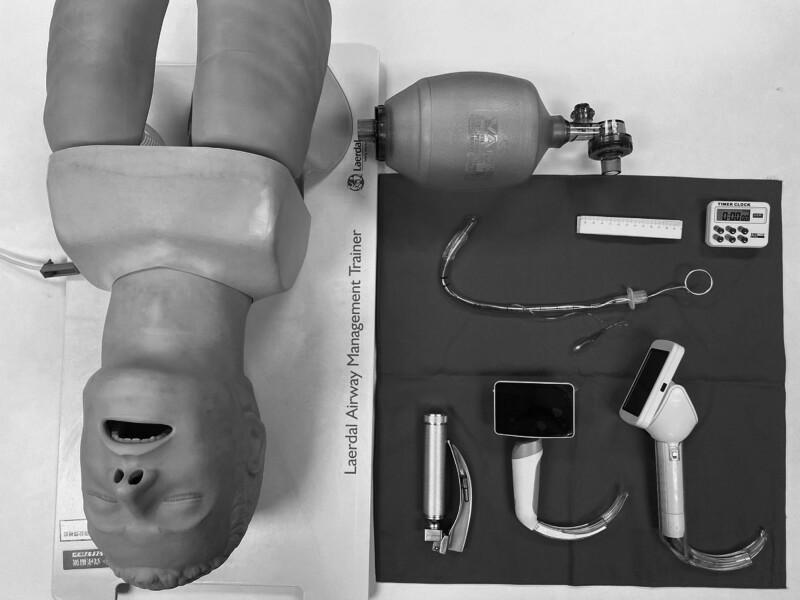
A high-angle clinical photograph displays standard and advanced airway management equipment for endotracheal intubation, positioned alongside a Laerdal Airway Management Trainer mannequin. The equipment includes three types of laryngoscopes: a conventional Macintosh-style laryngoscope with a metal handle and curved blade, and two video laryngoscopes featuring integrated digital screens and specialized curved blades for enhanced glottic visualization. Also present is a Bag Valve Mask (BVM) for manual ventilation. Centrally located is a clear cuffed endotracheal tube (ETT) with an internal stylet bent into a 'hockey-stick' configuration to facilitate insertion; the ETT includes a visible pilot balloon, connector, and depth markings. Ancillary procedural tools include a ruler for measurement and a digital timer for monitoring intubation time. This setup is typical for anesthesia training, emergency medicine simulation, or comparative studies between direct and video laryngoscopy techniques.
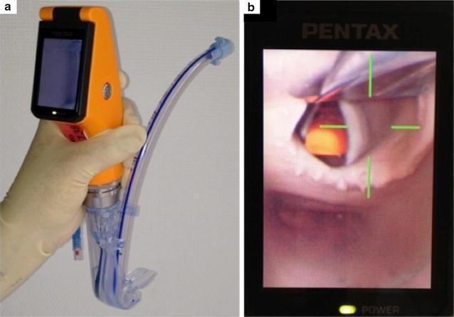
This composite image illustrates the design and clinical application of the Airway Scope® (AWS), a portable, battery-operated video-laryngoscope used for endotracheal intubation. Figure A shows the device's physical components: an orange handle with an integrated 6.1 cm LCD monitor and a single-use 'Intlock' blade. An endotracheal tube (ETT) with a blue radiopaque stripe is preloaded into the blade’s dedicated side-channel guide, which facilitates direct advancement into the trachea. Figure B demonstrates the device's functional output during indirect laryngoscopy. The LCD screen displays a real-time view of the upper airway, specifically focusing on the glottic opening. To assist the clinician, a green crosshair target is superimposed on the digital image; alignment of this target with the glottis indicates the correct path for ETT insertion. This visual aid is designed to simplify intubation by providing a wide viewing angle (180°) and clear anatomical visualization of the vocal cords, thereby potentially increasing first-pass success rates in both novice and expert practitioners.
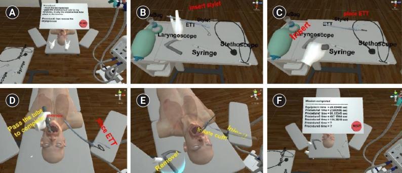
A series of six panels (A-F) from a virtual reality (VR) medical training simulation focused on endotracheal intubation. (A) Shows the overall virtual clinical environment with a patient mannequin and instructional interface. (B & C) Focus on the equipment table, labeling essential airway management tools: Bag Valve Mask (Ambu Bag), laryngoscope with a curved blade (Macintosh type), endotracheal tube (ETT), stylet, syringe for cuff inflation, and stethoscope. In panel C, a virtual hand demonstrates inserting the stylet into the ETT. (D & E) Depict the clinical procedure on the mannequin. In (D), the laryngoscope is used to visualize the airway while the ETT is passed into the trachea. In (E), the laryngoscope is removed, and a syringe is used to inflate the ETT distal cuff to secure the airway and prevent aspiration. (F) Displays a summary screen of procedure times for performance assessment. This instructional content is designed for medical training in airway management, anesthesia, or emergency medicine, demonstrating the chronological steps of preparing equipment, intubation, and cuff management.
anaesthesia drugs induction propofol fentanyl syringe preparation
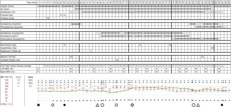
A comprehensive perioperative anesthetic record presented as a chronological time-series graph (0 to 255 minutes). The top portion uses a grid format to track medication administration, including induction agents (Propofol, Fentanyl), inhalational anesthetics (Sevoflurane), vasoactive infusions (Epinephrine, Phenylephrine, Dobutamine, Nicardipine), and neuromuscular blockers (Rocuronium). Below the drug grid, numerical rows record End-Tidal Carbon Dioxide (EtCO2) and cerebral oximetry via Near-Infrared Spectroscopy (NIRS) for both left and right hemispheres. The bottom section features a multi-parameter hemodynamic trend graph plotting blood pressure (red X for systolic/diastolic), heart rate (green line), central venous pressure (dark blue dots), oxygen saturation (SpO2), and temperature. Standardized clinical symbols along the x-axis denote critical procedural events: arterial and central line placement, tracheal intubation/extubation, abdominal insufflation/desufflation, Trendelenburg positioning, aortic valve opening, and transesophageal echocardiogram (TEE) insertion. This record illustrates the complex management of a patient undergoing surgery, likely involving cardiac and laparoscopic components, requiring tight hemodynamic control via multiple titration-sensitive medications.
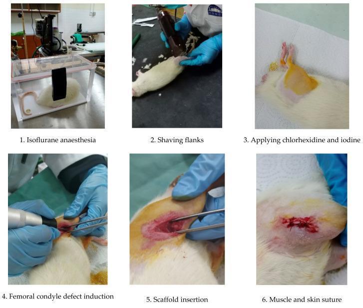
This composite educational image illustrates a six-step surgical workflow for scaffold implantation in an animal model, specifically a white rat. The timeline serves as a protocol for orthopedic research in regenerative medicine. 1. Pre-operative Preparation: The sequence begins with 'Isoflurane anaesthesia' in a transparent induction chamber, followed by 'Shaving flanks' using an electronic clipper. The third frame shows aseptic technique through 'Applying chlorhexidine and iodine,' evidenced by the yellow antiseptic staining on the skin. 2. Surgical Procedure: The fourth frame depicts 'Femoral condyle defect induction' using a handheld micro drill to create a standardized bone void. This is followed by 'Scaffold insertion,' where a biomaterial (chitosan-based) is placed into the defect using surgical forceps. 3. Closure: The final frame shows 'Muscle and skin suture,' demonstrating the post-operative appearance with absorbable sutures. The content highlights key stages of translational medical research, focusing on surgical site preparation, orthopedic defect creation, and biomaterial integration. It is intended for researchers and students studying surgical techniques and tissue engineering.
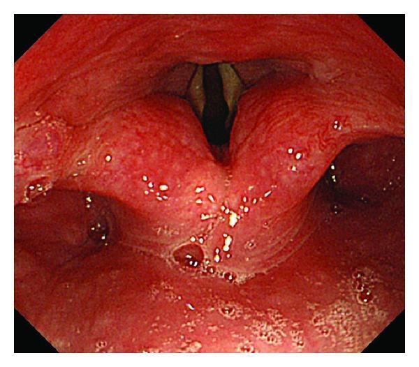
This clinical photograph shows a laryngoscopic view of the human hypopharynx and larynx during propofol induction. The primary focus is the glottic opening, where the true vocal cords (vocal folds) are visible as elongated, pale structures positioned centrally. The vocal cords are partially abducted, revealing a dark, narrow glottic space; however, the tracheal cartilage is not visualized due to the degree of glottic closure. The surrounding supraglottic structures, including the arytenoids and aryepiglottic folds, exhibit a pinkish-red hue with areas of surface cobblestoning and minor secretions (visible as bright white specks), which may indicate mild irritation or chronic inflammation. The piriform recesses are visible on either side. This diagnostic image serves as an educational tool for evaluating laryngeal anatomy, vocal cord patency, and airway assessment during pharmacological sedation. Key educational concepts include glottic visualization, mucosal assessment, and pharyngeal function during anesthesia.
Pre-Anaesthesia Preparation: Complete Guide
1. ANAESTHESIA MACHINE PREPARATION
- Reliable delivery of oxygen at any concentration up to 100%
- Reliable means of positive-pressure ventilation
- Backup ventilation equipment available and functional
- Controlled release of positive pressure from the breathing circuit
- Anaesthetic vapour delivery (if planned)
- Adequate suction
- Means to conform to patient monitoring standards
Step-by-Step Machine Checkout (ASA 15-Item List)
| # | Item | Action |
|---|---|---|
| 1 | Backup/emergency ventilation | Verify a self-inflating bag-valve device + separate O2 source (cylinder with flowmeter) is present. Non-self-inflating Mapleson circuits are NOT adequate. |
| 2 | Patient suction | Verify suction is adequate with tubing of appropriate length + Yankauer tip |
| 3 | AC power | Power on workstation; confirm AC power (not running on battery backup) |
| 5 | Spare O2 cylinder | Open cylinder on back of machine; verify adequate pressure; close valve after check |
| 6 | Pipeline gas pressures | Verify piped gas pressures ≥50 psig for O2, air, N2O |
| 8 | Low-pressure system leak check | Close flow control valves; attach suction bulb to fresh gas outlet; squeeze repeatedly until fully collapsed; verify bulb stays collapsed ≥10 seconds; repeat with each vaporizer open |
| # | Item | Action |
|---|---|---|
| 2 | Suction | Re-verify before every case |
| 4 | Monitors + alarms | Confirm SpO2 probe, NIBP cuffs, capnography; test alarm thresholds at established defaults |
| 7 | Vaporizer | Verify adequate agent fill level; ensure filler port tightly closed |
| 9 | O2 monitor calibration | Reads 21% in room air → flush with O2 → reads >90%; low-O2 alarm enabled |
| 10 | Breathing circuit | Check circuit complete, undamaged, unobstructed; CO2 absorbent adequate |
| 11 | Breathing circuit + APL valve | Occlude Y-piece; fill circuit; check for leaks; APL valve function |
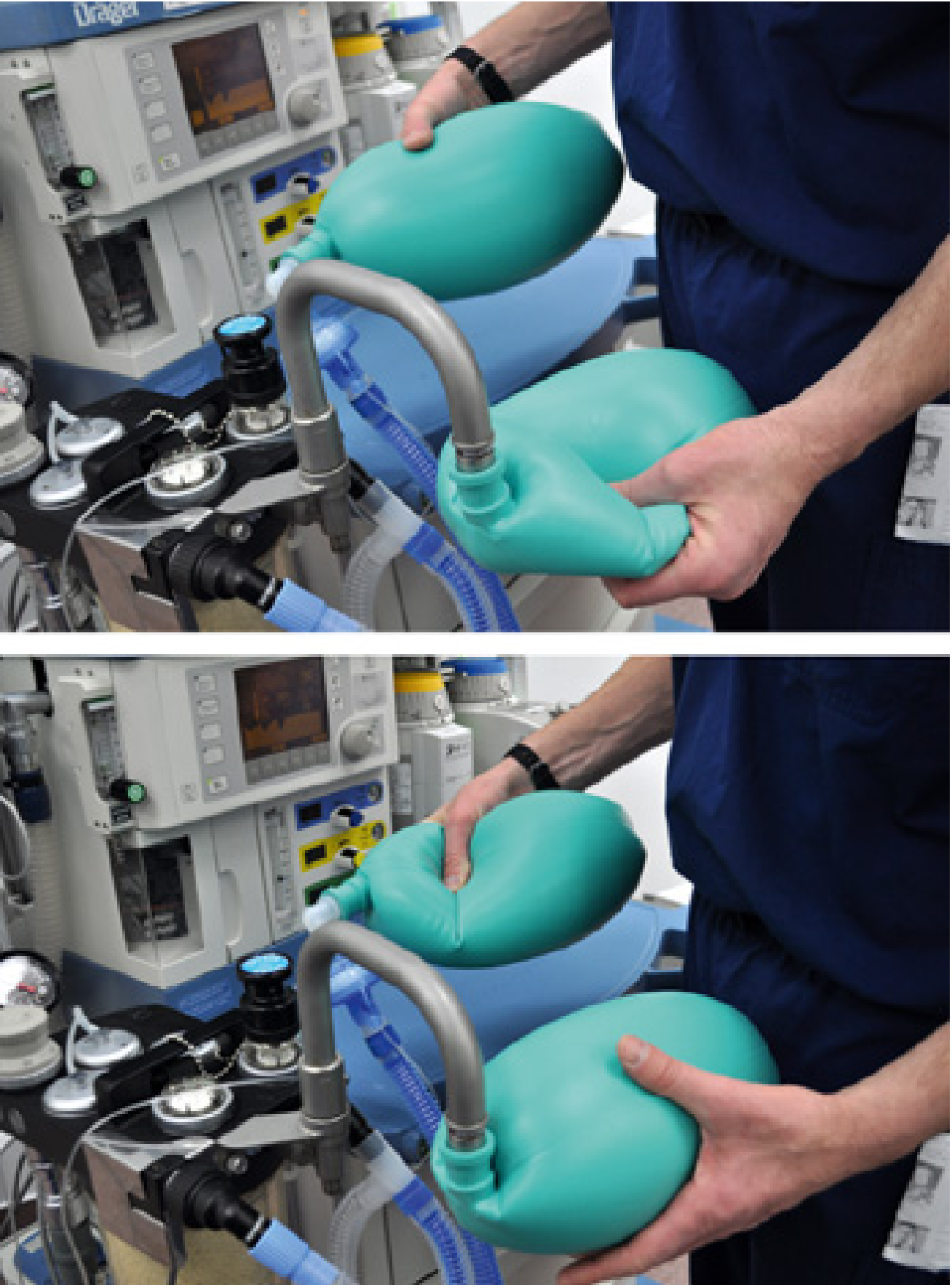
| 12 | One-way valves | Flow test - "to-and-fro" test (see figure below) |
| 13 | Flowmeters | Smooth operation across full range; attempt hypoxic mix → alarm/prevention activates |
| 14 | Scavenging system | Proper connections to APL valve and ventilator relief valve; adjust waste-gas vacuum |
| 15 | Anaesthesia Time-Out | Monitors functional? Capnogram present? SpO2 measured? Flowmeter/ventilator settings correct? Manual/ventilator switch to Manual? Vaporizer filled? |
Final Mnemonic - MS MAIDS
- M - Machine (circuit, gases, vaporizer)
- S - Suction
- M - Monitors (SpO2, NIBP, ECG, capnography)
- A - Airway (intubation kit, difficult airway trolley)
- I - IV access
- D - Drugs (drawn up and labelled)
- S - Special equipment for the case
2. INTUBATION KIT PREPARATION
Essential Equipment
| Item | Details |
|---|---|
| Laryngoscope | Macintosh curved blade (sizes 2, 3, 4) - most common; Miller straight blade for difficult airways; test light before use |
| Video laryngoscope | Available as backup (e.g. McGrath, C-MAC, GlideScope) |
| Endotracheal tubes (ETT) | Cuffed tubes: ID 7.0-7.5 mm (women), 8.0-8.5 mm (men); have one size smaller available. Uncuffed for children |
| Stylet | Pre-bent into "hockey-stick" shape; lubricated; tip should not protrude beyond ETT end |
| 10 mL syringe | For cuff inflation after intubation |
| Magill forceps | For nasal intubation or foreign body retrieval |
| Oral/nasal airway | Guedel airways (sizes 80, 90, 100 mm) for airway maintenance before intubation |
| Face mask | Correct size with cushion seal; connect to breathing circuit or BVM |
| Self-inflating BVM | For pre-oxygenation and emergency ventilation |
| Tape/tie | To secure ETT after intubation |
| Stethoscope | For bilateral breath sounds + epigastric check post-intubation |
| CO2 detector | Colorimetric ETCO2 or waveform capnography to confirm placement |
| Lubricant | Water-soluble jelly for tube and stylet |
| Surgical suction | Yankauer sucker at hand; active, tested before induction |
Pediatric ETT Sizing (from Tintinalli's Emergency Medicine)
| Age | ETT Internal Diameter | Blade Size |
|---|---|---|
| Premature | 3.0 mm uncuffed | 0 straight |
| 0-6 months | 3.5 mm cuffed | 1 straight |
| 6-12 months | 4.0 mm cuffed | 1-1.5 straight |
| 1-2 years | 4.5 mm cuffed | 1.5 straight |
| 3-4 years | 4.5 mm cuffed | 1.5-2 straight or curved |
| Adults (F) | 7.0-7.5 mm | Macintosh 3 |
| Adults (M) | 8.0-8.5 mm | Macintosh 3-4 |
Difficult Airway Backup
- Supraglottic airway (LMA) - sizes 3 (small adult), 4 (adult), 5 (large adult)
- Intubating LMA (Fastrach)
- Cricothyrotomy kit
- Flexible fibreoptic bronchoscope
3. SUCTION MACHINE PREPARATION
Preparation Checklist
| Step | Action |
|---|---|
| 1 | Turn on suction unit; verify power source (wall/battery) |
| 2 | Check suction pressure: -80 to -120 mmHg (100-150 mmHg for rigid suction) |
| 3 | Attach suction tubing of appropriate length to reach patient airway |
| 4 | Attach Yankauer suction tip (rigid, angled) - primary for oropharyngeal suctioning |
| 5 | Have flexible suction catheter available (for nasopharyngeal or through ETT) |
| 6 | Verify canister is empty/below fill line |
| 7 | Check all connections are secure and airtight |
| 8 | Test suction by occluding the tip - vacuum should hold |
| 9 | Position within immediate reach of anaesthetist at head end of patient |
4. ANAESTHESIA DRUGS PREPARATION
Standard Drug Trolley Layout
A. Induction Agents
| Drug | Dose | Notes |
|---|---|---|
| Propofol | 1-2.5 mg/kg IV | Most common; milky white; painful on injection; reduces BP |
| Thiopentone (Thiopental) | 3-5 mg/kg IV | Rapid onset; avoid in porphyria |
| Ketamine | 1-2 mg/kg IV / 4-6 mg/kg IM | Preserves airway reflexes; dissociative; useful in haemodynamic compromise |
| Etomidate | 0.2-0.3 mg/kg IV | Haemodynamically stable; avoid for maintenance (adrenal suppression) |
B. Analgesics / Opioids
| Drug | Dose | Notes |
|---|---|---|
| Fentanyl | 1-3 mcg/kg IV | Short-acting; attenuates intubation response |
| Morphine | 0.1-0.2 mg/kg IV | Longer duration; post-op analgesia |
| Remifentanil | 0.5-1 mcg/kg IV bolus or infusion | Ultra-short; must be on infusion |
C. Neuromuscular Blocking Agents (NMBAs)
| Drug | Class | Dose | Onset | Duration |
|---|---|---|---|---|
| Suxamethonium (Succinylcholine) | Depolarising | 1.5 mg/kg IV | 60 seconds | 8-12 min |
| Rocuronium | Non-depolarising | 0.6 mg/kg (RSI: 1.2 mg/kg) | 90-120 sec | 30-60 min |
| Vecuronium | Non-depolarising | 0.1 mg/kg IV | 3-5 min | 25-40 min |
| Atracurium | Non-depolarising | 0.5 mg/kg IV | 2-3 min | 20-35 min |
D. Reversal Agents
| Drug | Dose | Indication |
|---|---|---|
| Neostigmine | 0.05 mg/kg IV (max 5 mg) | Reversal of non-depolarising NMBAs |
| Atropine | 0.02 mg/kg IV | Given with neostigmine to prevent bradycardia |
| Sugammadex | 2-16 mg/kg IV | Reversal of rocuronium/vecuronium; faster and more complete |
E. Volatile Agents (Vaporizer)
| Agent | MAC | Properties |
|---|---|---|
| Sevoflurane | 1.85% | Smooth induction; non-pungent; preferred for inhalational induction |
| Isoflurane | 1.15% | Cheaper; pungent; mainly maintenance |
| Desflurane | 6.6% | Rapid emergence; heated vaporizer required |
| Nitrous oxide (N2O) | 104% | Adjuvant; analgesic; reduces agent requirement |
F. Benzodiazepines (Pre-medication/Amnesia)
| Drug | Dose | Notes |
|---|---|---|
| Midazolam | 1-2 mg IV | Anxiolytic, amnesic, anticonvulsant |
| Diazepam | 0.1-0.2 mg/kg IV | Longer acting; premedication |
G. Emergency / Resuscitation Drugs (must always be drawn or immediately available)
| Drug | Purpose | Dose |
|---|---|---|
| Atropine | Bradycardia | 0.6-1.2 mg IV |
| Ephedrine | Hypotension | 6-12 mg IV boluses |
| Adrenaline (Epinephrine) | Anaphylaxis / cardiac arrest | 0.5-1 mg IV (cardiac arrest); 0.5 mg IM (anaphylaxis) |
| Phenylephrine | Hypotension (vasopressor) | 50-100 mcg IV |
| Labetalol/Metoprolol | Hypertension/tachycardia | As needed |
| Sodium bicarbonate | Acidosis/cardiac arrest | 1 mEq/kg IV |
| Dantrolene | Malignant hyperthermia | 2.5 mg/kg IV (repeat prn) |
| Suxamethonium | Laryngospasm/RSI | 1.5 mg/kg IV |
| Intralipid 20% | Local anaesthetic toxicity | 1.5 mL/kg bolus |
Drug Labelling Rules
- Every syringe must be labelled with drug name, concentration, date, and time
- Use colour-coded labels per international standard (e.g. yellow = opioids, orange = NMBAs, aqua = induction agents)
- Never leave unlabelled syringes on the drug tray
Quick Reference Summary
ANAESTHESIA MACHINE   → O2 cylinders, pipeline pressures, vaporizer fill,
                         breathing circuit leak test, CO2 absorbent,
                         scavenging, monitors, backup ventilation

INTUBATION KIT        → Laryngoscope (tested), ETT (sizes), stylet, BVM,
                         10 mL syringe, Magill forceps, oral airway,
                         tape, stethoscope, CO2 detector, LMA backup

SUCTION               → Yankauer tip, adequate pressure (-100 mmHg),
                         tubing connected, tested, within arm's reach

DRUGS                 → Induction agent + opioid + NMBA drawn & labelled
                         Reversal (neostigmine/sugammadex) ready
                         Emergency drugs available (atropine, ephedrine,
                         adrenaline, dantrolene, intralipid)