
Surgical anatomy of inner ear in detail and various techniques of cochlear implant surgery in detail according to standard ENT textbook in simplified manner
Surgical anatomy of inner ear in detail and various techniques of cochlear implant surgery in detail according to standard ENT textbook in simplified manner
cochlear implant surgical anatomy inner ear cochlea diagram
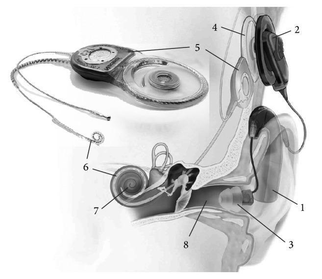
This medical anatomical diagram and clinical illustration depict a hybrid cochlear implant system and its placement within the human ear. The image features a cross-sectional view of the ear anatomy and an inset showing the standalone hardware. External components include a behind-the-ear sound processor (1) connected to an earmould (3) in the external auditory canal (8) for acoustic amplification, and an external transmitter coil (2). Internal components include an implanted receiver/stimulator coil (4) and the main implant body (5) positioned subcutaneously. A flexible electrode array (6) is shown extending into the spiraled cochlea (7) of the inner ear. The diagram illustrates the dual mechanism of hybrid stimulation: electric stimulation of the auditory nerve via the intracochlear electrodes and acoustic amplification of low-frequency sounds through the earmould. Key landmarks include the external auditory meatus, tympanic membrane, ossicular chain, and the snail-shaped cochlea, demonstrating the pathway from sound capture to neural excitation.
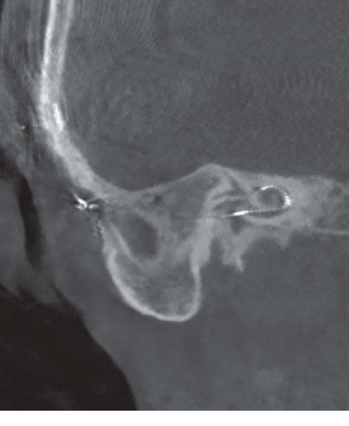
This diagnostic image is a post-operative Computed Tomography (CT) scan of the right temporal bone, focused on the inner ear anatomy. The image demonstrates a cochlear implant in situ, following a primary implantation procedure. The electrode array is clearly visible as a curved, hyperdense (radiopaque) metallic structure positioned within the fluid-filled spaces of the cochlea. Specifically, the electrode is shown following the spiral trajectory of the basal turn, with an insertion depth of approximately 290 degrees. Key anatomical landmarks visible include the bony labyrinth of the cochlea, the mastoid process with its air cells, and the outline of the tympanic cavity. The image serves as an educational example of post-surgical verification for cochlear implant positioning, highlighting the spatial relationship between the prosthetic electrode and the delicate spiral architecture of the inner ear. It illustrates the clinical standard for assessing electrode array placement and ensuring correct anatomical orientation within the cochlear duct.
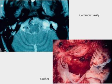
This composite educational graphic features two distinct medical images related to cochlear implant (CI) surgery in cases of inner ear malformations. The upper left diagnostic image is a high-resolution axial computerized tomography (CT) scan of the temporal bones with a teal-colored filter. It demonstrates a 'Common Cavity' malformation, characterized by a single confluent ovoid cystic space representing the vestibulocochlear organ, lacking a distinct cochlea and vestibule. The lower right image is an intraoperative clinical photograph showing a surgical site during mastoidectomy. The field is heavily obscured by an active 'gusher,' a significant outflow of cerebrospinal fluid (CSF) or perilymph from the cochleostomy, often associated with wide internal auditory canal connections in malformed ears. Visible in the surgical field are blood, exposed soft tissues, and white mesh-like packing or surgical sponges used to manage the fluid egress. These images highlight the diagnostic and intraoperative challenges faced during cochlear implantation in patients with complex inner ear anatomy.
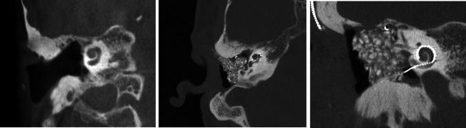
This set of diagnostic images features coronal Cone-Beam Computed Tomography (CBCT) scans of the human petrous bone, comparing preoperative and postoperative states for cochlear implantation. The baseline image shows the native anatomy of the inner ear, including the spiral architecture of the cochlea and the surrounding temporal bone density. The postoperative images demonstrate the successful placement of a cochlear implant. A highly radio-opaque, coiled electrode array is clearly visible within the cochlear lumen, following the scalar tympani curve to stimulate the auditory nerve. Additionally, the surgical field shows evidence of mastoid cavity modification and the presence of filling materials (such as Bonalive or abdominal fat) used for site obliteration. These images serve as a clinical example of using intraoperative or immediate postoperative imaging to verify electrode positioning and surgical outcomes in patients with complex or altered temporal bone anatomy, facilitating high-resolution assessment of the relationship between the hardware and inner ear microstructures.
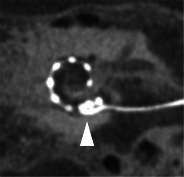
This diagnostic image is a Cone-Beam Computed Tomography (CBCT) paraaxial maximum intensity projection (MIP) focusing on the inner ear anatomy. It demonstrates a cochlear implant electrode array positioned within the cochlea. The electrode is visualized as a spiral series of hyperdense (bright), discrete contacts that follow the cochlear turns. A white arrowhead indicates a specific surgical complication: a basal fold-over. In this malposition, the proximal (basal) portion of the electrode array has bent or doubled back on itself within the basal turn of the cochlea, rather than following a smooth spiral insertion. This image is used in otolaryngology and radiology to evaluate post-operative cochlear implant placement and to identify mechanical insertion complications that can impact auditory outcomes. The CBCT modality provides high spatial resolution with reduced metal artifact compared to standard HRCT, allowing for detailed visualization of individual electrode contacts relative to the bony cochlear walls.
inner ear anatomy bony labyrinth cochlea vestibule semicircular canals surgical
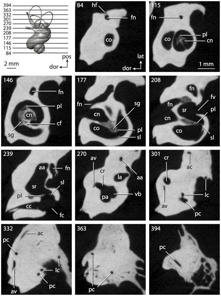
This diagnostic image provides a series of high-resolution CT slices through the petrosal bone, detailing the anatomy of the inner ear. The image set illustrates the complex three-dimensional structure of the bony labyrinth, with specific focus on the cochlea and vestibular apparatus. Slices 84 through 208 show the progressive coiling of the cochlea (co), revealing internal features such as the primary bony lamina (pl), cochlear canal (cn), and secondary bony lamina (sl). The relationship between the cochlea and the facial nerve canal (fn) is visible in the more anterior slices. Progressing posteriorly (slices 239–394), the vestibular system becomes prominent, showcasing the vestibule (vb), spherical recess (sr), and the three semicircular canals: anterior (ac), lateral (lc), and posterior (pc). Key landmarks for anatomical indexing include the fenestra cochleae (fc), fenestra vestibuli (fv), and the common crus (cr). These slices demonstrate the spatial orientation and morphology of the hearing and balance organs within the temporal bone, serving as a critical educational resource for understanding inner ear anatomy and radiological identification of its components.
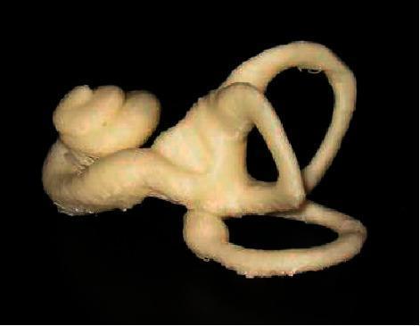
This image presents a 3D computational reconstruction of the human inner ear, derived from a statistical shape model. The anatomical diagram demonstrates the complex three-dimensional relationship between the cochlea, vestibule, and semicircular canals. On the left, the spiral-shaped cochlea is clearly visible with its characteristic bulbous, snail-like winding. This transitions into the central vestibule, from which the three semicircular canals (superior, posterior, and lateral) originate. These canals are depicted as arched, looped structures oriented in nearly orthogonal planes, illustrating their physiological role in sensing rotational head movements. The model features a pale, textured surface, representing the bony labyrinth, set against a high-contrast black background. This visual serves as an educational tool for understanding otolaryngology and vestibular anatomy, particularly for medical students and clinicians studying diagnostic imaging segmentation or the pathophysiology of inner ear disorders like Meniere's disease.
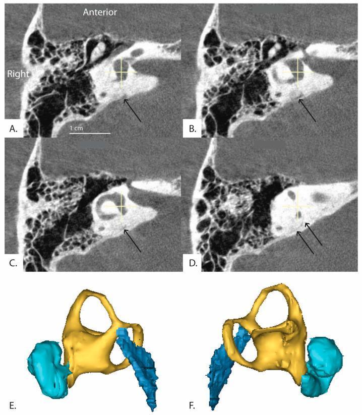
This composite educational resource features high-resolution imaging of the human inner ear anatomy. Panels A-D display sequential axial CT images reformatted in the plane of the horizontal semicircular canal, progressing from an inferior to superior perspective. Black arrows highlight the distal vestibular aqueduct as it traverses the petrous temporal bone. The images demonstrate the spatial relationship between the bony labyrinth, including the vestibule and semicircular canals, and the vestibular aqueduct. Panels E and F provide 3D anatomical reconstructions (right and left views, respectively) illustrating the complex spatial morphology of these structures. The color-coding in the 3D models differentiates key components: the cochlea is shown in cyan, the vestibule and semicircular canals in yellow, and the vestibular aqueduct in dark blue. This visualization is intended to assist in the clinical assessment of inner ear pathologies, such as Meniere's disease or superior canal dehiscence syndrome, by mapping the trajectory and angle of the vestibular aqueduct relative to the labyrinthine structures.
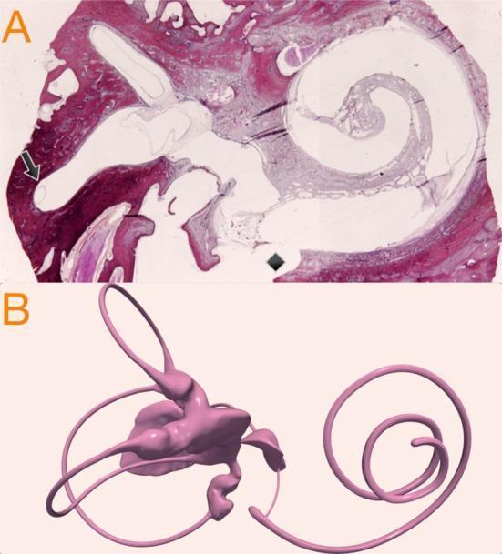
This dual-panel image displays the anatomy of the human inner ear through histological and volumetric reconstruction. (A) A Hematoxylin and Eosin (H&E) stained histological section of the temporal bone in a parasagittal plane. It clearly shows the coiled architecture of the cochlea and vestibular components. A black arrow identifies the endolymphatic horizontal duct within the osseous space, highlighting the spatial ratio between the membranous and bony canals. A black diamond indicates a post-mortem promontorial cochleostomy, demonstrating endosteal layer injury and traumatic penetration of the scala tympani. (B) A micro-CT volumetric 3D reconstruction of the endolymphatic spaces within the membranous labyrinth. The model, rendered in pink, illustrates the integrated fluid-filled anatomy including the spiral cochlea, the utricle and saccule within the vestibule, and the three semicircular canals. This figure serves as an anatomical reference for inner ear pathology, specifically regarding endolymphatic hydrops and surgical access to the cochlear base.
posterior tympanotomy mastoidectomy cochlear implant surgical approach facial recess
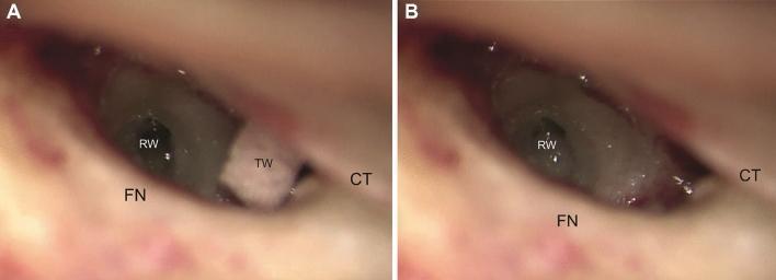
Side-by-side intraoperative clinical photographs (A and B) showing a microscopic view of the right ear round window (RW) niche through a facial recess approach. Image A (pre-drilling) demonstrates the surgical anatomy following cortical mastoidectomy and posterior tympanotomy, with the round window partially obscured by a bony overhang. Key landmarks include the facial nerve (FN) located inferiorly, the chorda tympani nerve (CT) positioned distally, and a tissue wipe (TW) placed for moisture control. Image B (post-drilling) illustrates the 'extended round window technique,' where antero-inferior drilling of the bony margin and crista fenestrae has been performed to optimize exposure for cochlear implant electrode insertion. This surgical modification provides a clearer, more direct line of sight into the scala tympani. The anatomical relationship between the facial nerve and chorda tympani remains constant, serving as the borders of the facial recess through which the middle ear is accessed. This comparison is essential for surgical training in otology and cochlear implantation.

A series of three intraoperative clinical photographs showing a posterior tympanotomy (facial recess approach) in a right ear, a critical step in cochlear implant surgery. Panel A demonstrates a 2 mm surgical diamond burr positioned within the facial recess opening, serving as a scale to indicate adequate surgical dimensions for instrument access. Panels B and C highlight the critical anatomical landmarks surrounding the opening: the facial nerve (FN) is clearly identifiable on the posterior margin with an intact posterior external auditory canal wall, and the chorda tympani nerve (CTN) defines the anterior-superior border. Through the surgically created window, the round window (RW) is visualized posteroinferiorly, providing the target site for electrode insertion into the basal turn of the cochlea. The series illustrates a 'normal' surgical view where all anatomical boundaries are preserved and the round window is easily accessible for direct membrane insertion. This content is intended for otolaryngology surgical training and preoperative planning.
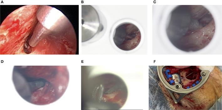
This composite of clinical and diagnostic images demonstrates the intraoperative validation of a minimally invasive cochlear implant (CI) surgical technique using a mini-stereotactic frame and patient-specific jigs. (A-E) Endoscopic and microscopic views of the facial recess (posterior tympanotomy) in multiple patients. The images show various sizes of sham drill bits (1.5 mm and 1.8 mm) being passed through the surgically exposed facial recess to evaluate the accuracy of a planned robotic trajectory. The surgical site displays anatomical landmarks including the facial nerve (FN) canal, chorda tympani, and the thinned external auditory canal (EAC). (F) A clinical photograph showing a titanium C-shaped mini-stereotactic frame fixated to a patient's skull posterior to the ear. The frame is secured via bone screws and holds a blue patient-specific positioning jig with fasteners. This assembly guides the drill path relative to the mastoidectomy site. The educational focus is on robotic-assisted otologic surgery, stereotactic navigation, and the spatial constraints of the facial recess during CI electrode insertion.
Surgical Anatomy of the Inner Ear & Cochlear Implant Surgery
PART 1: SURGICAL ANATOMY OF THE INNER EAR
Overview
- Bony labyrinth - the outer shell of hard bone
- Membranous labyrinth - the delicate soft tissue structures inside
A. The Bony Labyrinth
- Endosteal layer (inner)
- Periosteal layer (outer)
- Middle layer - made of enchondral/intrachondrial bone with cartilage islands called globuli interossei
This middle intrachondrial layer is unique - it does NOT remodel after infections, which is why labyrinthitis ossificans is so destructive.
B. The Cochlea
| Feature | Detail |
|---|---|
| Shape | Spiral, 2½ turns around the modiolus |
| Height | 5 mm |
| Base | Abuts the fundus of the internal auditory canal (IAC); perforated (cribrose) for cochlear nerve fibers |
| Apex | Lies medial to the tensor tympani muscle |
- Osseous spiral lamina - winds around the modiolus
- Basilar membrane - along with the osseous spiral lamina, separates the cochlear duct from the scala tympani
- Three scalae (fluid channels):
- Scala vestibuli - above the basilar membrane; contains perilymph
- Scala media (cochlear duct) - the membranous compartment; contains endolymph
- Scala tympani - below the basilar membrane; contains perilymph; the target for cochlear implant electrode
C. The Modiolus
- The central bony axis of the cochlea
- Contains the spiral ganglion cells (the target neurons for electrical stimulation)
- Normal spiral ganglion cell count: 25,000-35,000 cells
- Perforated to allow cochlear nerve fibers to pass through to the IAC
D. The Round Window
- Located at the base of the cochlea, opening into the scala tympani
- Covered by the round window membrane (secondary tympanic membrane)
- In some cases a veil of mucosa (false membrane) covers it - important to recognize surgically
- Crista fenestrae - the bony lip/overhang around the round window niche that may need drilling for access
- A microfissure runs from the round window niche to the ampulla of the posterior semicircular canal - a potential route for perilymph leakage
E. The Oval Window
- Located on the medial wall of the middle ear
- Contains the stapes footplate
- Connected to the scala vestibuli
- The fissula ante fenestram (anterosuperior to oval window) and fossula post fenestram (posterior) are perilymphatic evaginations filled with fibrous tissue - relevant in otosclerosis and stapedectomy
F. The Vestibule
- Central chamber of the bony labyrinth, 4 mm in diameter
- Medial wall has depressions for:
- Saccule - spherical recess
- Utricle - elliptical recess
- Cochlear duct - cochlear recess
- "Mike's dot" (macula cribrosa superior) - a cribrose area marking the passageway for superior vestibular nerve fibers; corresponds to the extreme lateral IAC - a key landmark in translabyrinthine surgery
G. The Semicircular Canals
| Canal | Orientation | Also called |
|---|---|---|
| Lateral | Horizontal plane | Horizontal canal |
| Superior | Anterior vertical plane | Anterior canal |
| Posterior | Posterior vertical plane | Posterior canal |
- Each has an ampullated limb (2 mm diameter) and a non-ampullated limb (1 mm diameter)
- The non-ampullated limbs of the posterior and superior canals fuse to form the crus commune
- Trautmann's triangle - the triangle bounded by the bony labyrinth, sigmoid sinus, and superior petrosal sinus
- Donaldson's line - an extension of the plane of the lateral semicircular canal that bisects the posterior canal; the endolymphatic sac lies inferior to this line - key landmark in endolymphatic sac surgery
H. The Membranous (Endolymphatic) Labyrinth
- Cochlear duct (scala media)
- Three semicircular ducts with their cristae ampullares (sensory organs for rotation)
- Utricle and saccule (otolithic organs for linear acceleration and gravity)
- Endolymphatic duct and sac
I. The Internal Auditory Canal (IAC)
| Feature | Detail |
|---|---|
| Average diameter | 3.4 mm |
| Average length | 8 mm |
| Contents | Facial nerve, cochlear nerve, superior & inferior vestibular nerves, labyrinthine artery & vein |
- Horizontal (falciform) crest - divides superior nerves from inferior
- Vertical crest ("Bill's bar") - separates the facial nerve (anterior) from the superior vestibular nerve (posterior)
J. Surgical Fissures of the Bony Labyrinth
- Fissula ante fenestram - evagination anterosuperior to the oval window; filled with fibrous tissue/cartilage in adults
- Fossula post fenestram - posterior to oval window; less constant
- Hyrtl's fissure (tympanomeningeal hiatus) - embryological remnant; rare; can be a route for CSF leakage into the middle ear
PART 2: COCHLEAR IMPLANT SURGERY - TECHNIQUES
What is a Cochlear Implant?
- External parts: microphone, sound processor, transmitter coil
- Internal parts: receiver-stimulator (implanted under the skin) + electrode array (inserted into the cochlea)
Patient Selection Criteria
- Adults: PTA > 70 dB bilaterally; open-set sentence recognition ≤60% in best-aided condition (HINT test at 55 dB HL)
- Children: age ≥12 months (earlier in some protocols)
- Narrow IAC (<3 mm) - adverse predictor; but not absolute contraindication
Technique 1: Transmastoid Approach via Facial Recess (Standard Technique)
Step 1 - Incision
- A postaural (retroauricular) incision is made
- Sufficient length to introduce the implant
- Important: The incision must NOT be placed directly over the receiver-stimulator package to minimize wound breakdown and extrusion
Step 2 - Periosteal Flap
- Soft tissue dissected down to periosteum
- Periosteum incised to create an anteriorly or posteriorly based flap
Step 3 - Cortical Mastoidectomy
- A complete cortical mastoidectomy is performed
- Identifies the:
- Sigmoid sinus (posterior limit)
- Tegmen (superior limit)
- Lateral semicircular canal (deep landmark)
- Facial nerve (posterior tympanotomy boundary)
Step 4 - Receiver-Stimulator Bed
- A subperiosteal pocket is created to house the receiver-stimulator
- Some surgeons drill a well in the cortical bone for secure fixation
- A gutter (groove) is often drilled in the bone for the electrode wire as it passes into the mastoid cavity
Step 5 - Posterior Tympanotomy (Facial Recess Approach)
- The facial recess is opened - the space bounded by:
- Facial nerve (posteriorly/medially)
- Chorda tympani nerve (anteriorly)
- Annulus of tympanic membrane (laterally)
- Opening must be wide enough to pass a 2 mm drill bit through it
- Chorda tympani is preserved where possible
Step 6 - Entry into the Cochlea
| Method | Description | Notes |
|---|---|---|
| Cochleostomy | Drill a small hole anterior and inferior to the round window | Traditional method; keeps electrode away from spiral ligament |
| Round window membrane insertion | Open the round window membrane itself after drilling away the bony niche | Less drilling; increasingly preferred |
| Extended round window technique | Drill antero-inferiorly to expand the niche | Better visualization for electrode direction |
Step 7 - Electrode Insertion
- Electrode inserted gently into the cochlea
- Full insertion preferred (~2.5 turns)
- Insertion should be slow and atraumatic to preserve residual hearing
Step 8 - Sealing
- Soft tissue (muscle/fat) seal placed around the electrode entry point to prevent perilymph leak and infection
Step 9 - Wound Closure
- Residual electrode wire coiled within the mastoid cavity
- Wound closed in layers
Technique 2: Suprameatal Approach
- Access to the middle ear is gained above the external auditory meatus through the suprameatal triangle
- Does not require a full mastoidectomy
- Electrode passed through the suprameatal route into the middle ear
- Less widely adopted; useful where mastoid anatomy is challenging
Technique 3: Transcanal / Endoscopic Cochlear Implantation
- Electrode is routed through the epitympanum after creating a well for the receiver
- A small cortical mastoidectomy provides access to the middle ear via the epitympanum
- Ear canal skin is raised from the bony EAC without transection
- Implant guided into cochleostomy under endoscopic guidance
- An alternative: electrode passed down a bony groove in the posterior EAC wall into the middle ear; groove filled with bone wax
- Minimally invasive
- No risk to facial nerve from posterior tympanotomy
- Elevation of tympanic membrane may create additional route for mesotympanum infection
- Cases of electrode extrusion through the posterior EAC skin have been reported, requiring explantation
Challenging Surgical Scenarios
1. Cochlear Ossification (Post-Meningitis)
- Ranges from minimal bone at the proximal basal turn to complete obliteration
- Pre-op MRI + CT together gives best assessment
- Management:
- Early ossification: drill through immature bone to reach the cochlear duct distally
- If duct cannot be found: partial insertion into drilled channel, OR dual-array electrode (second channel drilled anterior to oval window)
- Complete ossification: consider Auditory Brainstem Implant (ABI) instead
2. CSF/Perilymph Gusher
- Occurs with abnormal inner ear (e.g., X-linked deafness, enlarged vestibular aqueduct syndrome, common cavity)
- Mechanism: deficient partition between modiolus and dural envelope at IAC lateral end
- Management:
- Raise head of patient
- Wait for flow to slow, then insert electrode
- Pack muscle/soft tissue tightly around electrode entry point
- Post-op lumbar drain if leak persists
3. Cochlear Malformations
- Common cavity, incomplete partition, cochlear hypoplasia
- Smaller spiral ganglion populations (average 11,478 vs. normal 25,000-35,000)
- Higher complications: facial nerve stimulation, electrode malpositioning, CSF gusher (~40%)
- Malpositioning risk: electrode may penetrate IAC causing facial twitching at low stimulation thresholds
- Post-implantation CT advised before first stimulation to confirm electrode position
4. Otosclerosis
- Round window may be partially or completely obstructed by spongiotic bone
- May require extra drilling/cochlear drill-out
- Higher risk of non-auditory stimulation (facial twitching, otalgia, dizziness) due to demineralized otic capsule
- Perimodiolar electrode preferred when CT shows otic capsule involvement between facial canal and cochlea basal turn
Hearing Preservation Surgery
- Indication: patient has good low-frequency hearing but poor high-frequency hearing
- Leads to combined electro-acoustic stimulation (EAS) - electric stimulation for high frequencies + acoustic amplification for low frequencies
- Techniques to minimize cochlear trauma:
- Shorter or full-length "soft" electrodes
- Slow electrode insertion
- Round window membrane insertion (less traumatic than cochleostomy)
- Steroids: dexamethasone IV at induction; triamcinolone-soaked spongistan on round window pre-insertion; post-op oral steroids
Post-Operative Imaging
- Post-implantation CT should be done in all cases with:
- Malformed cochlea (confirm position before stimulation)
- Suspected electrode misplacement (fold-over, insertion into wrong scala)
- CBCT with MIP reconstruction best shows individual electrode contacts and their relationship to cochlear walls
Complications Summary
| Complication | Cause | Management |
|---|---|---|
| Facial nerve injury | Posterior tympanotomy, malpositioning | Intraoperative facial nerve monitoring |
| Facial nerve stimulation | Demineralized otic capsule (otosclerosis), electrode in wrong scala | Re-program or change electrode |
| CSF gusher | Inner ear malformation | Head elevation, soft tissue packing, lumbar drain |
| Electrode misplacement | Scala vestibuli insertion, fold-over | Post-op CT before activation |
| Wound breakdown/extrusion | Incision over implant | Careful incision planning |
| Device failure | Trauma, infection | Revision implantation |
| Meningitis | Post-CI (especially in children) | Pneumococcal vaccination pre-operatively |
Key Surgical Landmarks - Quick Summary
| Landmark | Significance |
|---|---|
| Facial nerve | Posterior border of facial recess; must be identified and preserved |
| Chorda tympani | Anterior border of facial recess |
| Round window | Entry to scala tympani for electrode |
| Lateral semicircular canal | Landmark for mastoid depth and Donaldson's line |
| "Bill's bar" (vertical crest) | Separates facial from superior vestibular nerve in IAC |
| "Mike's dot" | Passageway for superior vestibular nerve; marks lateral IAC - key in translabyrinthine surgery |
| Donaldson's line | Extension of lateral SCC plane; endolymphatic sac lies inferior |
| Trautmann's triangle | Bounded by bony labyrinth, sigmoid sinus, superior petrosal sinus |
| Modiolus | Central cochlear axis; contains spiral ganglion cells |