Central cord syndrome
Central Cord Syndrome
Overview
Anatomy & Pathophysiology
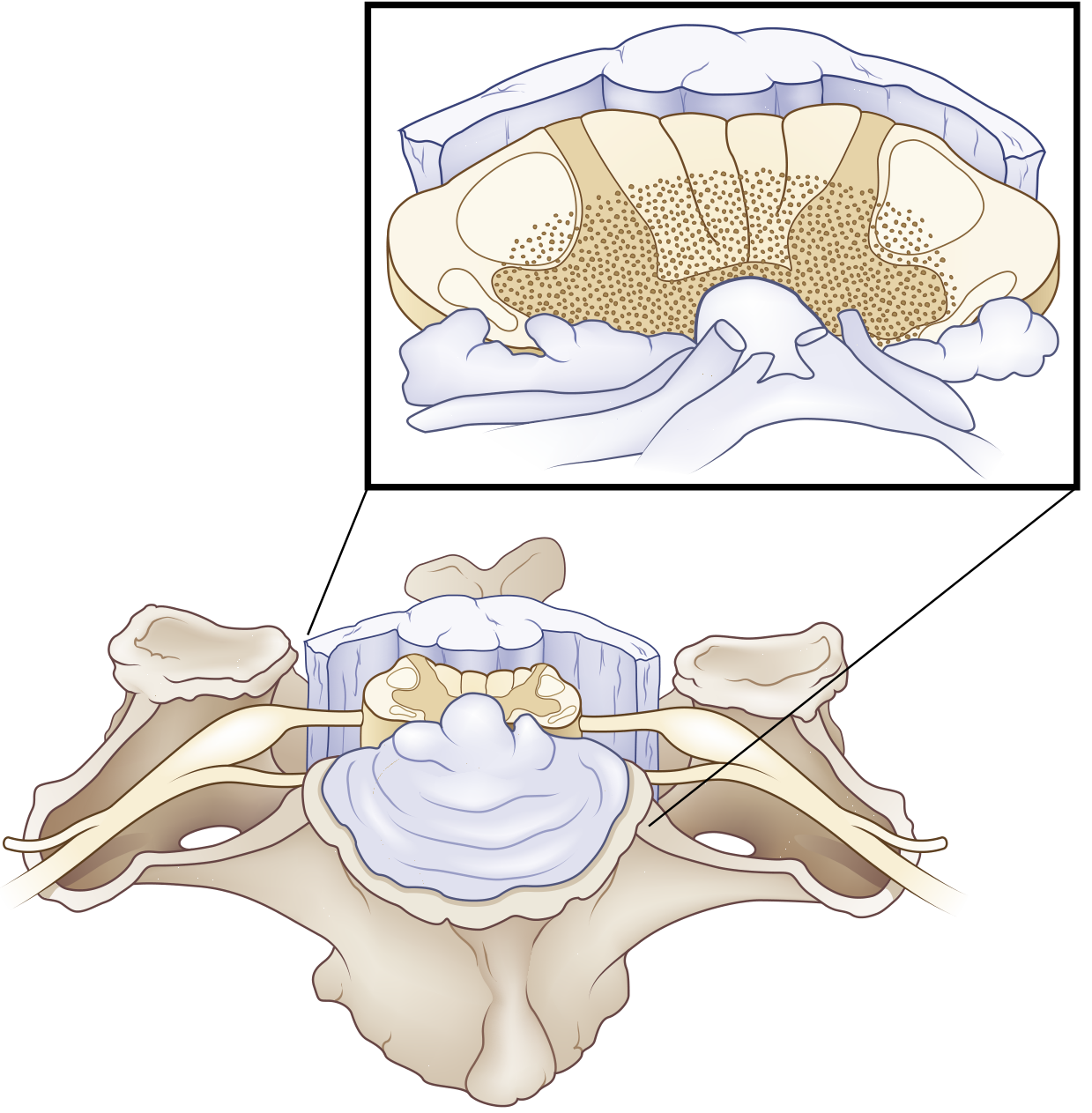
- Corticospinal tracts — the fibres supplying the upper extremities are located medially (closest to the central gray), while those for the lower extremities, thorax, and sacrum are located more laterally
- Spinothalamic tracts — centrally located crossing fibres
- Intramedullary decussating fibres — direct injury to these accounts for the dissociated sensory loss
Causes / Aetiology
| Cause | Details |
|---|---|
| Cervical hyperextension (most common) | Falls and MVAs in elderly patients with pre-existing cervical spondylosis |
| Cervical spinal stenosis | Pre-existing degenerative changes predispose |
| Disruption of blood flow | Vascular injury to central cord |
| Syringomyelia | Expanding syrinx (also posttraumatic) |
| Intrinsic tumour / myelitis | Less common non-traumatic causes |
Clinical Features
- Motor weakness — upper extremities > lower extremities (disproportionately so)
- Bladder dysfunction — urinary retention (most common)
- Sensory disturbance — variable degree
The "MUD" Mnemonic (Rosen's EM):
Motor > sensory deficits
Upper extremities > lower extremities
Distal > proximal weakness
Additional features:
- Dissociated sensory loss: pain and temperature sensation impaired; vibration and proprioception preserved (posterior columns spared)
- Cape-like sensory deficit at cervical level — the area served by the damaged crossing spinothalamic fibres
- Spastic paraparesis or quadriparesis in more severe cases
- Bowel and bladder control usually retained in milder cases; impaired in severe ones
- Quantitative criterion: ≥10 motor score point difference (MRC scale) between upper and lower extremities
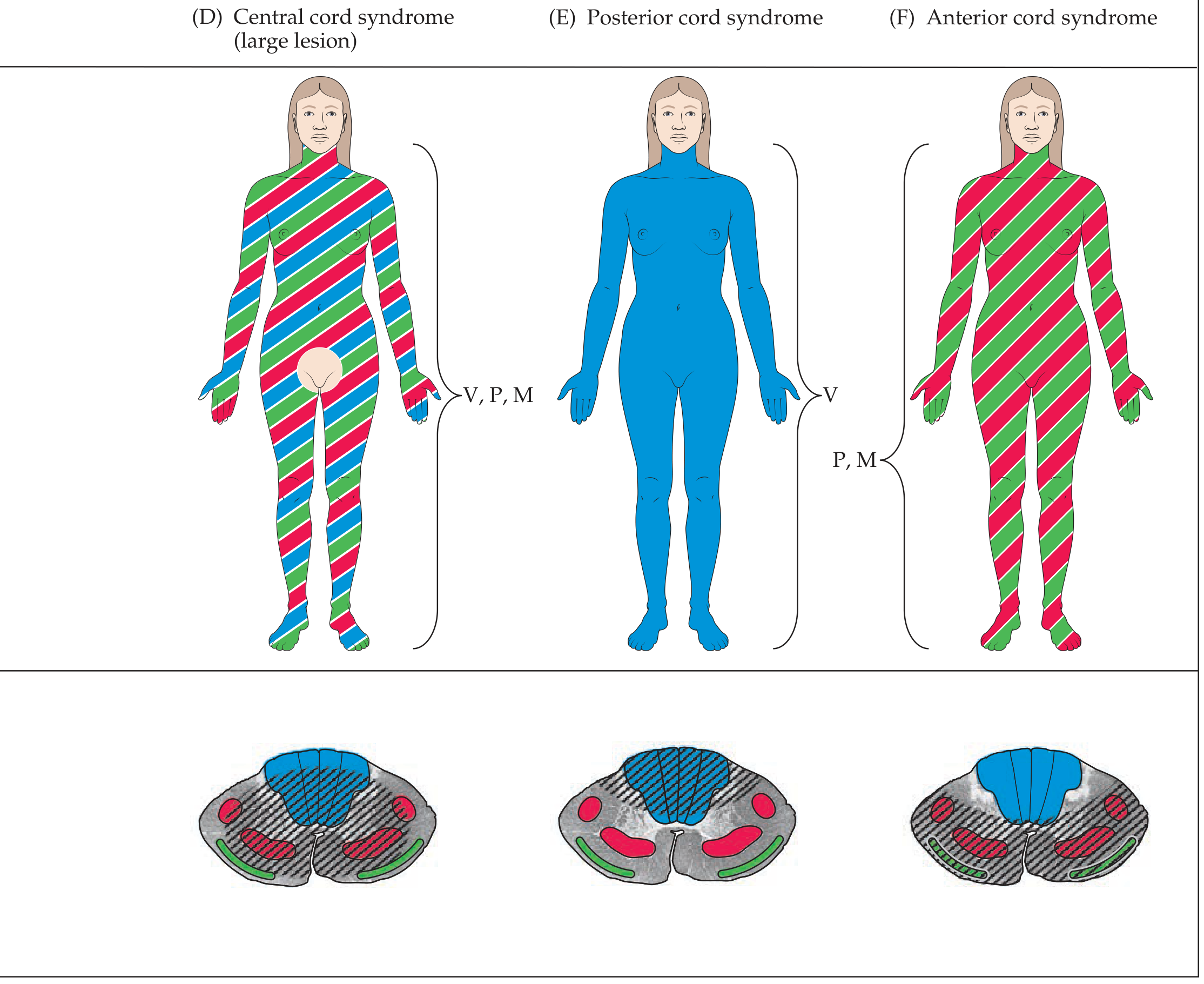
Comparison with Other Incomplete Cord Syndromes
| Syndrome | Mechanism | Deficits | Prognosis |
|---|---|---|---|
| Central cord | Hyperextension + stenosis | Quadriparesis UE > LE; pain/temp loss UE > LE; bladder dysfunction | Good |
| Anterior cord | Flexion, disc/bone fragment, anterior spinal artery thrombosis | Complete paralysis + loss of pain/temp below lesion; proprioception/vibration preserved | Poor |
| Brown-Séquard | Hemisection (penetrating trauma) | Ipsilateral motor + proprioception/vibration loss; contralateral pain/temp loss | Good |
Imaging
- Cervical stenosis from spondylosis
- Fracture-subluxation or sequestered disc
- Cord signal change (oedema or haemorrhage)
- No radiographic abnormality (SCIWORA) in some cases
Management
Acute Phase:
- Spinal immobilisation and stabilisation
- Blood pressure management (MAP target ≥85 mmHg to maintain cord perfusion)
- Urinary catheterisation for retention
- Avoid steroids (no longer routinely recommended)
Surgical vs. Conservative:
- Surgery within 24 hours of traumatically induced CCS is safe and more cost-effective than delayed procedures (Rockwood and Green's Fractures in Adults, citing Chen et al.)
- Surgical decompression is indicated when imaging shows compressive pathology
Rehabilitation:
- Physical and occupational therapy targeting hand/arm function (the most impaired and slowest to recover)
- Bladder retraining
- Spasticity management
Prognosis
- Generally good among incomplete cord syndromes
- Recovery pattern: lower extremity function tends to recover first and best; bladder function next; hand/fine motor function recovers last and least
- Elderly patients and those with more severe initial deficits have worse outcomes
- Note: Among incomplete cord syndromes, anterior cord syndrome carries the worst prognosis; central cord and Brown-Séquard have comparatively better outcomes
Brown sequard syndrome for 10 marks question
Brown-Sequard syndrome spinal cord hemisection diagram
Brown-Séquard Syndrome
Definition
Anatomy & Pathophysiology
| Tract | Location in Cord | Decussation | Effect of Hemisection |
|---|---|---|---|
| Corticospinal tract | Ipsilateral lateral funiculus | Medulla (already crossed) | Ipsilateral UMN weakness below lesion |
| Dorsal columns (fasciculus gracilis/cuneatus) | Ipsilateral posterior funiculus | Medulla (decussates above) | Ipsilateral loss of vibration, proprioception, discriminative touch |
| Spinothalamic tract | Contralateral lateral funiculus | Crosses within 1–2 spinal segments of entry | Contralateral loss of pain & temperature 1–2 segments below lesion |
Aetiology
- Penetrating injuries — stab wounds, gunshot wounds (most common cause)
- Blunt trauma — hyperextension, locked facets, compression fractures
- Herniated cervical disc
- Multiple sclerosis
- Spinal cord tumours (primary or metastatic)
- Spinal epidural or subdural haematoma
- Haematomyelia
- Spinal cord ischemia (e.g., vertebral artery dissection)
- Infections / inflammatory myelitis (VZV, EBV, CMV, TB, sarcoidosis)
- Posttraumatic arachnoiditis
- Spinal cord herniation
Classic Clinical Features
1. Ipsilateral findings (same side as the lesion):
- UMN spastic paresis below the level of the lesion (corticospinal tract damage)
- Loss of vibration sense and proprioception below the level (dorsal column damage)
- Loss of discriminative (fine) touch below the level
- LMN weakness, atrophy, areflexia at the level of the lesion (anterior horn / ventral root involvement)
- Ipsilateral loss of pain & temperature at the level of the lesion (a narrow band — segmental)
- Ipsilateral Horner syndrome — if the lesion is cervical (interruption of descending sympathetic fibres)
- Ipsilateral loss of sweating below the lesion (descending autonomic fibres)
- Ipsilateral hemidiaphragm paralysis — if high cervical (UMN pathways for breathing)
2. Contralateral findings (opposite side):
- Loss of pain and temperature sensation beginning 1–2 segments below the level of the lesion (spinothalamic fibres ascend 1–2 levels before crossing, so the sensory loss level lags behind the lesion)
- Touch is relatively preserved (bilateral representation in the cord)
Key rule: Motor loss and proprioception loss are ipsilateral; pain and temperature loss is contralateral — and begins slightly below the anatomical level.
Brown-Séquard Plus Syndrome
- Asymmetric hemiplegia (weaker on one side)
- Hypoalgesia more prominent on the less paretic side
Diagnosis
- Clinical — the asymmetric pattern of ipsilateral motor/proprioceptive loss + contralateral pain/temperature loss is pathognomonic
- MRI spine — investigation of choice; shows cord signal change (T2 hyperintensity = oedema/myelomalacia), compressive lesion, or haematoma
- CT spine — for bony trauma / instability
- Sensory level examination — pin-prick testing to delineate the contralateral sensory level
Management
Acute:
- Spinal immobilisation; maintain MAP ≥85 mmHg
- Surgical decompression if compressive aetiology (tumour, haematoma, disc, fracture)
- Treat underlying cause (antibiotics for infection, steroids for inflammatory causes, anticoagulation reversal for haematoma)
Rehabilitation:
- Physiotherapy for motor recovery
- Bladder/bowel management if autonomic involvement
- Occupational therapy
Prognosis
- Most patients regain ambulatory capacity
- Most achieve bowel and bladder continence
- Patients with predominantly upper extremity weakness have a favourable prognosis for ambulation
- Recovery can be delayed — symptoms may appear or resolve in a delayed fashion, and BSS may co-exist with other cord syndromes
Summary Table — Incomplete Cord Syndromes
| Feature | Brown-Séquard | Central Cord | Anterior Cord |
|---|---|---|---|
| Motor | Ipsilateral UMN weakness | UE >> LE | Complete paralysis below |
| Proprioception/Vibration | Ipsilateral loss | Preserved | Preserved |
| Pain/Temperature | Contralateral loss | UE >> LE, impaired | Lost below lesion |
| Cause | Penetrating trauma | Hyperextension + spondylosis | Flexion / ASA thrombosis |
| Prognosis | Best | Good | Worst |
Neurogenic bladder automatic bladder each for 10 marks and comparison between other bladder neural involvement
neurogenic bladder classification types diagram cystometrogram
Neurogenic Bladder — Comprehensive 10-Mark Answer
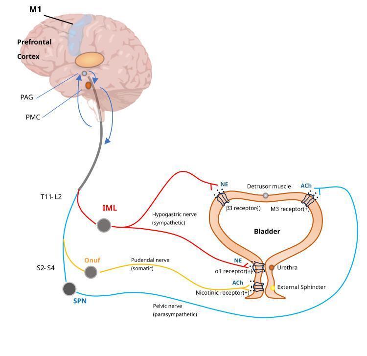
Normal Neural Control of Micturition (Essential Foundation)
| Level | Structure | Role |
|---|---|---|
| Cortex / Prefrontal | Voluntary control | Inhibits reflex voiding; allows socially appropriate timing |
| Pontine Micturition Centre (PMC) | Coordination centre | Coordinates detrusor contraction + sphincter relaxation |
| Sacral cord S2–S4 | Reflex arc | Parasympathetic (pelvic nerve) → detrusor contraction |
- Parasympathetic (S2–S4, pelvic nerve): ACh → M3 receptors → detrusor contraction (voiding)
- Sympathetic (T11–L2, hypogastric nerve): NE → β3 receptors → detrusor relaxation; α1 receptors → bladder neck contraction (storage)
- Somatic (S2–S4, Onuf's nucleus, pudendal nerve): ACh → nicotinic receptors → external urethral sphincter contraction (storage)
PART I: NEUROGENIC BLADDER (10 Marks)
Definition
Classification — Lapides System (1970)
1. Uninhibited Neurogenic Bladder
- Lesion: Cortex / corticoregulatory tract (suprapontine)
- Causes: CVA, brain tumour, Parkinson's disease, multiple sclerosis, dementia
- Mechanism: Loss of cortical inhibition → sacral micturition reflex overactive
- Features: Frequency, urgency, urge incontinence; voiding often incomplete; sensation intact or reduced; small-capacity bladder with normal/strong contractions
- Cystometry: Low-volume involuntary detrusor contractions; normal compliance
2. Reflex Neurogenic Bladder (Automatic Bladder)
- Lesion: Complete suprasacral spinal cord (above sacral segments, below pons)
- Causes: Traumatic spinal cord injury, transverse myelitis, advanced MS
- Mechanism: Spinal cord transection severs both sensory and motor pathways to/from brain; sacral reflex arc intact but disconnected from higher centres
- Features: No bladder sensation; no voluntary voiding; reflex (involuntary) voiding at low volumes; detrusor-sphincter dyssynergia (DSD); incontinence
- Cystometry: Detrusor overactivity (hyperreflexia); DSD on EMG
3. Autonomous Neurogenic Bladder
- Lesion: Complete destruction of sacral cord (S2–S4) or sacral nerve roots / pelvic nerves
- Causes: Spina bifida, conus medullaris tumour, pelvic surgery, trauma
- Mechanism: Complete motor AND sensory separation of the bladder from the sacral cord → loss of both reflex and voluntary control
- Features: No sensation; no voluntary or reflex voiding; bladder becomes flaccid/large; overflow incontinence; large post-void residual
- Cystometry: Detrusor areflexia; large capacity; low pressure; high compliance initially, may reduce with chronicity
4. Sensory Neurogenic Bladder
- Lesion: Afferent (sensory) fibres from bladder to spinal cord
- Causes: Diabetes mellitus (most common), tabes dorsalis, pernicious anaemia
- Mechanism: Loss of afferent stretch sensation → no urge to void → progressive overdistension
- Features: Insidious — gradual loss of urge sensation; bladder enlarges progressively; overflow incontinence in late stages; motor function intact initially
- Cystometry: Large capacity; flat, high-compliance filling curve; no sensation at normal fill volumes; large residual
5. Motor Paralytic Bladder (Motor Neurogenic Bladder)
- Lesion: Efferent (motor/parasympathetic) fibres from sacral cord to bladder
- Causes: Pelvic surgery, trauma, herpes zoster
- Mechanism: Detrusor motor denervation → inability to contract despite intact sensation
- Features: Urinary retention with painful distension; sensation preserved; inability to initiate voiding; may progress to overflow incontinence
- Cystometry: Normal filling; no voluntary detrusor contraction; large residual
Complications of Neurogenic Bladder
| Complication | Mechanism |
|---|---|
| Recurrent UTI | Residual urine as bacterial incubator; catheter use |
| Vesicoureteric reflux (VUR) | High intravesical storage pressure (>40 cmH₂O) |
| Hydronephrosis / Renal damage | Elevated storage pressure overcomes ureteric peristalsis |
| Bladder stones | Stasis + infection |
| Autonomic dysreflexia | Lesions above T6; bladder distension triggers uncontrolled hypertensive crisis |
Management
- Clean Intermittent Catheterisation (CIC) — gold standard for emptying in areflexic bladder
- Antimuscarinics (oxybutynin, tolterodine) — for detrusor overactivity/hyperreflexia
- Alpha-blockers — for smooth sphincter dyssynergia
- Botulinum toxin — intravesical for refractory detrusor overactivity
- Neuromodulation (sacral nerve stimulation, PTNS) — for overactive bladder
- Surgical — bladder augmentation (enterocystoplasty), Mitrofanoff procedure, urinary diversion, artificial urinary sphincter
- Urodynamic surveillance — essential; high-risk patients (SCI, spina bifida) need regular video-urodynamics to monitor pressures and prevent upper tract damage
PART II: AUTOMATIC BLADDER (Reflex Neurogenic Bladder) — 10 Marks
Definition
Anatomical Basis
- The pontine micturition centre (PMC) normally coordinates detrusor contraction with sphincter relaxation
- A suprasacral lesion disconnects this coordination centre from the sacral reflex arc
- The sacral cord (S2–S4) and the spinal micturition reflex arc remain intact
- Both afferent (stretch) signals from the bladder and efferent (motor) parasympathetic signals to the detrusor are preserved within the sacral cord
- However, both ascending afferent signals to the brain and descending inhibitory signals from the cortex/PMC are severed
Phases After Spinal Cord Injury
Phase 1 — Spinal Shock (days to weeks)
- Immediately after cord transection, all spinal reflexes below the lesion are suppressed (spinal shock)
- Bladder becomes atonic, flaccid, and overfills
- Overflow incontinence occurs with no reflex voiding
- Management: indwelling catheter or CIC to prevent bladder overdistension and damage
Phase 2 — Recovery / Automatic Bladder (weeks to months)
- As spinal shock resolves, the sacral micturition reflex gradually re-establishes
- Bladder becomes hyperreflexic — empties automatically at low volumes by spinal reflex
- Detrusor overactivity (hyperreflexia) develops
- Bladder capacity is reduced
- Voiding is unannounced, involuntary, incomplete — significant residual urine
Clinical Features
| Feature | Detail |
|---|---|
| No bladder sensation | Afferent signals cannot reach cortex |
| No voluntary voiding | Corticospinal pathway to PMC severed |
| Automatic/reflex voiding | Spinal reflex intact; void triggered by small volumes |
| Detrusor-sphincter dyssynergia (DSD) | Detrusor contracts but external sphincter also contracts simultaneously → impaired emptying, high pressure |
| Urge incontinence | Reflex contractions occur without warning |
| Large post-void residual | Due to DSD and incomplete emptying |
| Autonomic dysreflexia | If lesion above T6 — bladder distension triggers massive sympathetic discharge → severe hypertension, bradycardia, sweating, headache |
Urodynamic Findings (Cystometry)
- Reduced bladder capacity (voids at low volumes)
- Uninhibited/involuntary detrusor contractions (neurogenic detrusor overactivity)
- Detrusor-sphincter dyssynergia (simultaneous detrusor contraction + external sphincter contraction)
- High detrusor pressures (risk of upper tract damage if sustained >40 cmH₂O)
- No voluntary augmentation of voiding
Causes
| Category | Examples |
|---|---|
| Traumatic SCI | Most common; above sacral cord |
| Transverse myelitis | Inflammatory cord lesion |
| Multiple sclerosis | Demyelination of descending pathways |
| Spinal cord tumour | Compression above conus |
| Cervical spondylotic myelopathy | Chronic cord compression |
Management of Automatic Bladder
| Goal | Intervention |
|---|---|
| Safe bladder storage pressure | Anticholinergics (oxybutynin); Botulinum toxin intravesical |
| Complete emptying | CIC ± alpha-blockers (for sphincter dyssynergia) |
| Prevent autonomic dysreflexia | Avoid bladder overdistension; α-blockers |
| Trigger voiding (historical, not recommended) | Suprapubic tapping, Credé manoeuvre — NOT recommended (cause high pressures) |
| Surgical | Bladder neck incision for DSD; augmentation cystoplasty for compliance |
| Neuromodulation | Sacral nerve stimulation |
Important: Reflex bladder emptying and abdominal straining (Valsalva voiding) are NOT recommended because they generate high intradetrusor pressures that damage the upper urinary tract. — Smith & Tanagho's General Urology
PART III: COMPARISON OF ALL TYPES OF NEUROGENIC BLADDER
| Feature | Uninhibited | Reflex (Automatic) | Autonomous | Sensory | Motor Paralytic |
|---|---|---|---|---|---|
| Lesion site | Cortex / suprapontine | Suprasacral cord (below PMC) | Sacral cord / sacral roots / pelvic nerves | Afferent sensory pathway | Efferent motor (parasympathetic) pathway |
| UMN / LMN | UMN | UMN | LMN | Sensory only | Motor only |
| Causes | CVA, Parkinson's, MS, tumour | SCI, transverse myelitis | Conus/cauda equina injury, spina bifida, pelvic surgery | DM, tabes dorsalis, pernicious anaemia | Pelvic surgery, herpes zoster |
| Sensation | ↓ or present | Absent | Absent | Absent / grossly impaired | Normal / present |
| Voluntary voiding | Present (but poor control) | Absent | Absent | Present (uses timed voiding) | Absent (can't initiate) |
| Reflex voiding | Exaggerated (low volume) | Yes (spinal reflex) | Absent | Absent | Absent |
| Detrusor activity | Overactive (hyperreflexia) | Overactive (hyperreflexia) | Areflexic | Areflexic (late) | Areflexic |
| Sphincter | Synergic | Dyssynergic (DSD) | Variable — may be lax | Normal | Normal |
| Bladder capacity | Reduced | Reduced | Large / markedly increased | Very large | Large |
| Post-void residual | Mild–moderate | Large | Large | Large | Large |
| Compliance | Low (stiff) | Low (high pressure) | High initially → may decrease | High (very compliant) | Normal → decreases |
| Main risk | Urge incontinence, falls | Upper tract damage, DSD, autonomic dysreflexia | Overflow incontinence, UTI, silent renal damage | Overflow incontinence, silent renal damage | Acute urinary retention |
| Cystometry pattern | Early involuntary contractions at low volume | Hyperreflexia + DSD on EMG | Flat high-compliance curve, no contractions | Flat high-compliance curve, no sensation | Normal filling, no voluntary contraction |
| Prognosis | Good with treatment | Requires lifelong CIC and surveillance | Requires lifelong CIC | If treated early, good | Good if cause addressed early |
Key Principles to Remember
- Lesion above sacral cord (suprasacral) → Detrusor hyperreflexia + DSD (UMN pattern) — automatic / reflex bladder
- Lesion at sacral cord or below (infrapontine LMN) → Detrusor areflexia — autonomous/flaccid bladder
- Lesion above pons (suprapontine) → Detrusor hyperreflexia but synergic sphincter — uninhibited bladder
- Storage pressure >40 cmH₂O is the critical threshold above which renal damage occurs — urodynamic monitoring is mandatory
- Automatic (reflex) bladder is the most important exam type — represents the post-spinal shock stage of complete suprasacral SCI
Lumbar fusion surgeries and approaches for 10 marks each
Lumbar Fusion Surgeries and Approaches — 10 Marks Each
PART I: LUMBAR SPINAL FUSION — OVERVIEW (10 Marks)
Definition
Principles of Fusion
- Instrumentation — provides immediate mechanical stability (pedicle screws + rods, plates) while biological fusion occurs
- Bone grafting — provides the biological substrate for osseous union
Graft Types
| Type | Source | Use |
|---|---|---|
| Autograft | Iliac crest (most common), local bone from laminectomy | Gold standard; osteogenic, osteoconductive, osteoinductive |
| Allograft | Tissue bank (femoral rings, fibular struts, bone chips) | Structural support; no osteogenic potential |
| Synthetic | Tricalcium phosphate, hydroxyapatite, calcium sulphate | Bone substitutes |
| Biologics | rh-BMP-2 (recombinant bone morphogenetic protein) | Promotes osteogenesis |
| Interbody cages | PEEK, titanium, carbon composite | Load-bearing structural support; packed with graft material |
Metalwork provides temporary support only until uninterrupted osseous union is achieved. — Grainger & Allison's
Indications for Lumbar Fusion
| Condition | Rationale |
|---|---|
| Degenerative disc disease with instability | Eliminate painful motion segment |
| Spondylolisthesis | Reduce and stabilise slip |
| Lumbar stenosis with instability | Decompression + stabilisation |
| Recurrent disc herniation | After discectomy causes instability |
| Isthmic spondylolysis | Defect in pars interarticularis |
| Spinal fractures | Traumatic instability |
| Tumour resection | Reconstruction after corpectomy/vertebrectomy |
| Iatrogenic instability | After extensive laminectomy/facetectomy |
| Spinal deformity (scoliosis, kyphosis) | Corrective and stabilising |
| Pseudoarthrosis | Re-do fusion after failed first fusion |
Goals of Lumbar Fusion
- Decompression of neural structures (spinal cord, nerve roots)
- Stabilisation of the motion segment — reduce pain from abnormal movement
- Restoration of disc height and foraminal height
- Restoration of sagittal alignment (lumbar lordosis)
- Prevention of progression of deformity
Types of Lumbar Fusion by Location of Graft Placement
A. Posterolateral Fusion (PLF) — Intertransverse Fusion
- Bone graft placed between transverse processes and/or facet joints
- Combined with decompressive laminectomy and discectomy
- Does not enter the disc space
- Provides fusion of posterior column elements
- Facilitated by pedicle screws + rod construct
- Advantage: simpler; less neural retraction
- Disadvantage: no anterior column support; lower fusion rates than interbody techniques
B. Interbody Fusion
- Disc is removed and interbody cage + graft placed directly between vertebral bodies
- Restores disc height, foraminal height, and load-sharing at anterior column
- Higher fusion rates than PLF alone
- Multiple approaches (covered in detail in Part II)
C. 360° / Circumferential Fusion
- Combination of anterior interbody fusion + posterior instrumentation (pedicle screws + rods + posterolateral bone grafting)
- Provides maximum stability
- Indicated for severe instability, high-grade spondylolisthesis, revision surgery
- Higher fusion rates but more operative morbidity (two approaches)
Instrumentation
- Provide three-column fixation (anterior, middle, posterior columns)
- Rigid, strong, well-tolerated
- Risk: screw malposition → nerve root injury
- Other fixation options: translaminar screws, transfacet screws, hooks, wires
Complications of Lumbar Fusion
| Complication | Detail |
|---|---|
| Pseudoarthrosis | Failed bony union — most common reason for reoperation |
| Adjacent segment disease | Accelerated degeneration at unfused levels above/below |
| Hardware failure | Screw breakage, rod fracture (Fig. — fractured rods on imaging) |
| Cage migration | Especially posterior migration in TLIF/PLIF |
| Infection | Wound/deep infection, discitis |
| Dural tear / CSF leak | During decompression |
| Nerve root injury | Retraction or screw malposition |
| Retrograde ejaculation | Sympathetic plexus injury (ALIF approach) |
| Vascular injury | Aorta/IVC (anterior approaches) |
| Flat back syndrome | Loss of lumbar lordosis post-fusion |
| Postoperative visual loss (ION) | Prone positioning during long lumbar fusions |
PART II: APPROACHES FOR LUMBAR FUSION (10 Marks)
1. PLIF — Posterior Lumbar Interbody Fusion
- Patient prone; midline incision
- Bilateral laminectomy / laminotomy
- Bilateral facetectomy (partial or complete)
- Retraction of dural sac and nerve roots bilaterally
- Total discectomy; removal of cartilaginous end plates
- Bone graft / cage packed into disc space bilaterally
- Pedicle screw + rod fixation
- Direct visualisation of neural elements
- Single posterior incision
- Bilateral interbody support
- Good fusion rates — better than PLF alone for spondylolisthesis
- Extensive bilateral muscle stripping
- Significant dural retraction → risk of nerve root injury, dural tear
- High blood loss
- Epidural scar formation
2. TLIF — Transforaminal Lumbar Interbody Fusion
- Patient prone; midline or paramedian incision
- Unilateral facetectomy on symptomatic side
- Approach through the intervertebral foramen (Kambin's triangle) — avoids the dural sac
- Discectomy via unilateral corridor
- Curved/crescent-shaped cage inserted across the disc space
- Bone graft + bilateral pedicle screw-rod construct
- Less dural retraction than PLIF (unilateral approach)
- Single posterior incision — avoids anterior approach morbidity
- Lower risk to neural elements
- Can be done as MIS-TLIF (minimally invasive)
- Preserves contralateral musculature
- Unilateral disc clearance — less complete than bilateral PLIF
- Risk of cage migration
- Less restoration of lordosis than ALIF
MIS-TLIF uses tubular retractors and fluoroscopic guidance, minimising muscle damage and blood loss. — Miller's Anesthesia
3. ALIF — Anterior Lumbar Interbody Fusion
- Patient supine; left paramedian or midline abdominal incision (or laparoscopic)
- Retroperitoneal dissection → mobilisation of aorta, IVC, iliac vessels
- Complete discectomy via anterior disc space
- Large cage (lordotic) + graft placed with full endplate coverage
- Anterior plate/screws OR supplemented with posterior pedicle screws
- Largest cage footprint → best endplate coverage, highest fusion rate
- Maximal restoration of disc height and lumbar lordosis
- No posterior muscle dissection — posterior musculature preserved
- Excellent deformity correction
- Access to L4–L5 and L5–S1 (difficult to reach from other approaches)
- Risk of retrograde ejaculation (superior hypogastric plexus injury) — 1–5%
- Risk of vascular injury (aorta, IVC, iliac vessels)
- Requires vascular/access surgeon collaboration
- Cannot address posterior neural compression directly
- Bowel and urological complications
4. LLIF / XLIF — Lateral (Extreme) Lumbar Interbody Fusion (Direct Lateral Interbody Fusion — DLIF)
- Patient in lateral decubitus position
- Small flank incision; retroperitoneal dissection
- Blunt dilation through psoas muscle under intraoperative neuromonitoring (EMG) to avoid lumbar plexus
- Large wide cage placed at disc space under fluoroscopic guidance
- Can be supplemented with lateral plate or posterior pedicle screws
- Minimally invasive — minimal blood loss
- Large cage footprint → strong endplate contact, good fusion
- Avoids posterior muscle stripping and anterior vascular structures
- Can address T12–L4 levels efficiently (multiple levels in one position)
- Good for coronal deformity correction (adult degenerative scoliosis)
- Limited to L1–L4 (cannot reach L4–L5 easily; cannot reach L5–S1 due to iliac crest)
- Risk of lumbar plexus / genitofemoral nerve injury → thigh numbness, hip flexor weakness (most common complication)
- Requires neuromonitoring
- Peritoneal contents injury (occult)
5. OLIF — Oblique Lumbar Interbody Fusion (ATP approach)
- Patient lateral or supine with roll; oblique flank incision
- Retroperitoneal approach in the corridor between the great vessels anteriorly and the psoas posteriorly
- Avoids traversing the psoas (unlike XLIF)
- Cage inserted obliquely
- Supplemented with posterior fixation
- Avoids psoas → lower risk of lumbar plexus injury vs. XLIF
- Can access L5–S1 (unlike XLIF)
- Minimally invasive
- Applicable for L2–S1
- Risk of sympathetic plexus, ureter, vascular injury
- Technically demanding anatomy
- Less familiar approach
6. PLF — Posterolateral (Intertransverse) Fusion
- Bone graft placed between transverse processes and facets (outside the disc space)
- Combined with pedicle screw-rod instrumentation
- Simpler; no interbody work
- Lower fusion rates compared to interbody techniques
- Indicated where interbody access not needed or not possible
Summary Comparison of Approaches
| Approach | Direction | Levels | Cage Size | Lordosis | Muscle Damage | Key Risk | Best For |
|---|---|---|---|---|---|---|---|
| PLIF | Posterior bilateral | L1–S1 | Small/medium | Moderate | High (bilateral) | Nerve root retraction | Bilateral pathology, spondylolisthesis |
| TLIF | Posterior unilateral | L1–S1 | Medium (curved) | Moderate | Moderate | Cage migration | Most common; unilateral pathology |
| MIS-TLIF | Posterior unilateral | L1–S1 | Medium | Moderate | Minimal | Learning curve | Preferred MIS option |
| ALIF | Anterior | L4–S1 | Large (lordotic) | Best | None posteriorly | Vascular; retrograde ejaculation | L5–S1; max lordosis; deformity |
| XLIF/LLIF | True lateral (transpsoas) | L1–L4 | Wide | Moderate | Minimal | Lumbar plexus/thigh numbness | Multilevel; scoliosis; MIS |
| OLIF | Oblique anterior | L2–S1 | Medium-large | Good | Minimal | Sympathetic/vascular | MIS; L5–S1 access; avoids plexus |
| PLF | Posterior | L1–S1 | N/A | Minimal | High | Pseudoarthrosis | No interbody needed |
| 360° | Combined ant + post | L1–S1 | Large | Best | High | Both sets of complications | High-grade slip; revision; max instability |
Key Principles for Exam
- TLIF is the most commonly performed interbody fusion today — unilateral transforaminal approach, less neural retraction than PLIF
- ALIF gives the best lordosis correction and cage footprint — used especially at L5–S1
- XLIF/LLIF cannot reach L5–S1 due to the iliac crest — limited to L1–L4
- Pedicle screws + rods = gold standard instrumentation; three-column fixation
- Pseudoarthrosis = failed fusion — most common indication for revision surgery
- Adjacent segment disease = degeneration above/below fused levels — long-term complication of any fusion
Can u add pictures for alif tlif plif olif
ALIF anterior lumbar interbody fusion cage placement technique
TLIF PLIF transforaminal posterior lumbar interbody fusion technique surgical approach
Visual Guide to Lumbar Interbody Fusion Approaches
All Approaches — Trajectories at a Glance
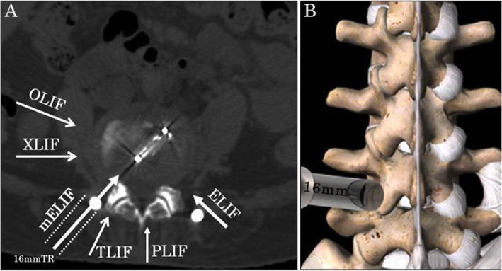
Panel A (axial CT): White arrows show entry corridors — OLIF and XLIF approach laterally/obliquely, TLIF through the foramen, PLIF from the direct posterior midline. Panel B: 3D view of a tubular retractor docked at the lateral facet for a minimally invasive approach.
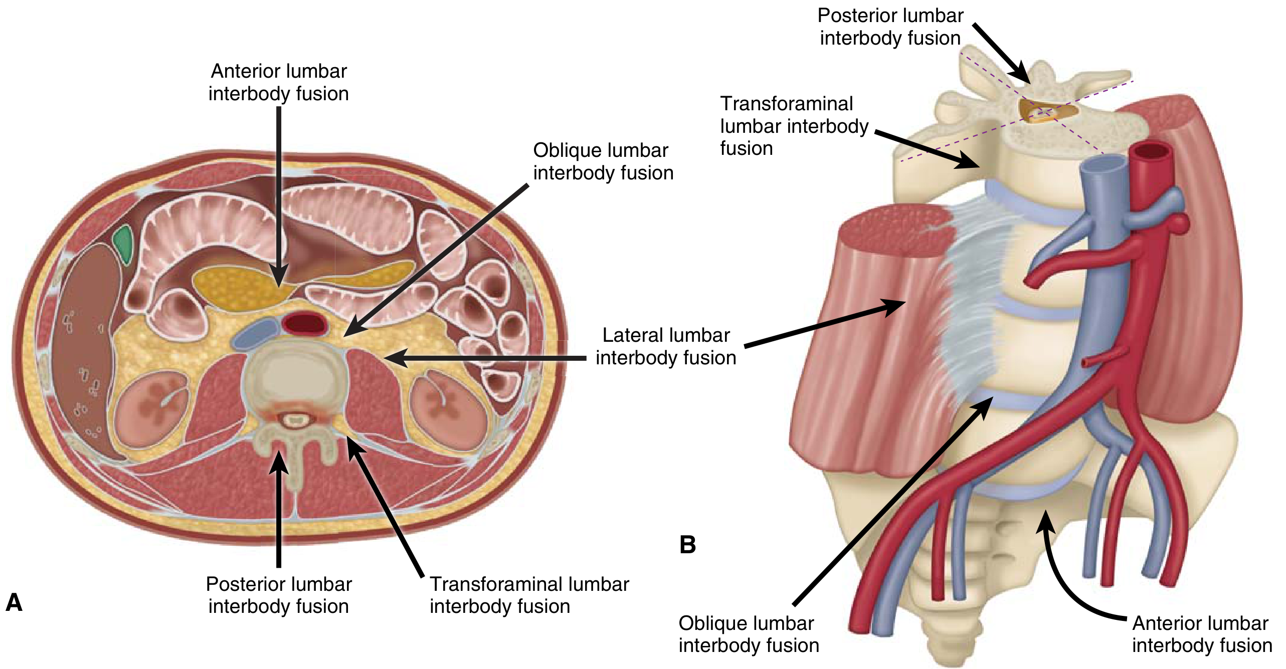
All Approaches — Schematic Diagram from Textbook
(Miller's Review of Orthopaedics, modified from Mobbs et al., 2015)
- ALIF = anterior (12 o'clock)
- OLIF = oblique anterolateral
- LLIF/XLIF = true lateral (3 or 9 o'clock)
- TLIF = oblique posterior through foramen
- PLIF = direct posterior bilateral
TLIF vs MIS-TLIF (Transforaminal LIF)
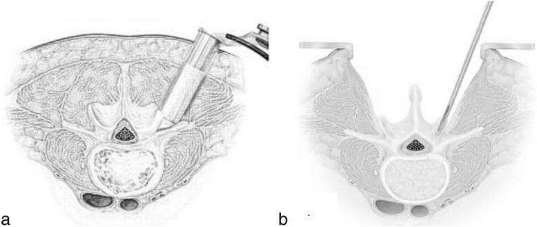
(a) MIS-TLIF: Tubular retractor angled obliquely through the foramen — minimal muscle disruption. (b) Open TLIF: Wide midline incision with bilateral paraspinal muscle retraction. Note how MIS-TLIF avoids the spinal canal, accessing the disc through Kambin's triangle.
TLIF vs PLIF vs MIS-TLIF — Postoperative Imaging Comparison
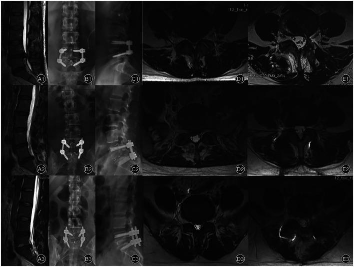
Rows 1–2 (TLIF/MIS-TLIF): Postoperative axial MRI (column E) shows preserved multifidus muscle bulk (dark, healthy signal). Row 3 (PLIF): Axial MRI shows significant multifidus atrophy and fatty infiltration (bright signal) due to bilateral muscle stripping — key disadvantage of PLIF over TLIF.
ALIF — Postoperative Radiograph (L5–S1)
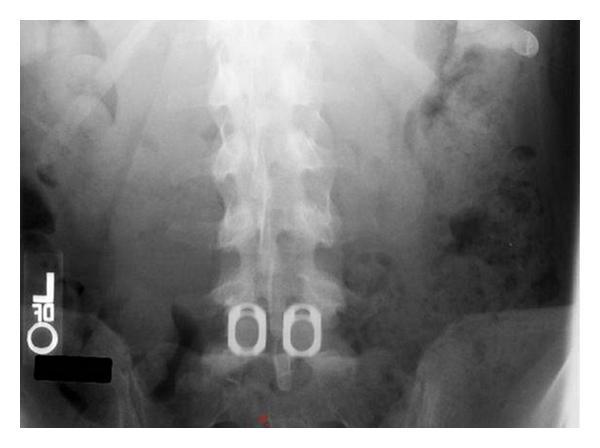
ALIF at L5–S1: Two large oval cages placed side-by-side in the disc space from the anterior approach. The wide cage footprint covering the ring apophysis (strongest endplate zone) is the hallmark of ALIF — maximising fusion surface area and lordosis correction.
Summary — Approach Corridors
| Approach | Direction | Disc Space Entry | Muscle Disruption | Key Limitation |
|---|---|---|---|---|
| ALIF | Anterior | Directly front | None (posterior) | Vascular/sympathetic risk |
| OLIF | Oblique anterolateral | Between vessels & psoas | Minimal | Sympathetic plexus |
| XLIF/LLIF | True lateral (transpsoas) | Through psoas | Minimal | L5–S1 inaccessible; lumbar plexus |
| TLIF | Posterior transforaminal | Unilateral foramen | Unilateral | Smaller cage than ALIF |
| PLIF | Posterior bilateral | Bilateral paramedian | Bilateral/extensive | Multifidus atrophy; nerve retraction |
Can u add pictures for alif tlif plif olif
-
All approaches together — the textbook schematic (Miller's Review of Orthopaedics) showing ALIF, OLIF, LLIF, TLIF, and PLIF trajectories in both axial and 3D views
-
All approaches on CT — axial CT with overlaid arrows labelling OLIF, XLIF, TLIF, and PLIF corridors
-
TLIF / MIS-TLIF — illustrated axial diagram comparing open vs minimally invasive transforaminal approach
-
TLIF vs PLIF comparison — postoperative X-rays + MRI showing muscle atrophy difference between PLIF and TLIF
-
ALIF — AP radiograph showing two large interbody cages at L5–S1 after anterior approach
- Search for different/clearer images for any specific approach
- Find intraoperative photos instead of X-rays
- Generate a labelled diagram illustrating each approach
Klippel-Feil syndrome for 10 marks question
Klippel-Feil syndrome short neck low hairline fused cervical vertebrae X-ray
Klippel-Feil Syndrome — 10 Marks
Definition
Embryology / Pathogenesis
- Normal segmentation of cervical vertebrae occurs between the 3rd and 8th weeks of fetal development (somitogenesis)
- KFS results from failure of normal segmentation of mesodermal somites during this critical window
- This leads to block vertebrae — fusion of vertebral bodies, posterior elements, or both
- The exact mechanism involves disruption of notch signalling and the segmentation clock
- Most cases are isolated and idiopathic; familial cases occur (autosomal dominant or recessive)
- Associated gene mutations: GDF6, GDF3, MEOX1, MYO18B
Classic Clinical Triad (Triad of Feil)
| Feature | Description |
|---|---|
| 1. Short neck | Reduced cervical height due to fused vertebrae |
| 2. Low posterior hairline | Hairline extends low onto the back of the neck/shoulders |
| 3. Restricted neck movement | Limited rotation and lateral flexion of the cervical spine |
The classic triad is present in only ~50% of cases — many patients have partial features or are diagnosed incidentally on imaging.
Clinical Photographs
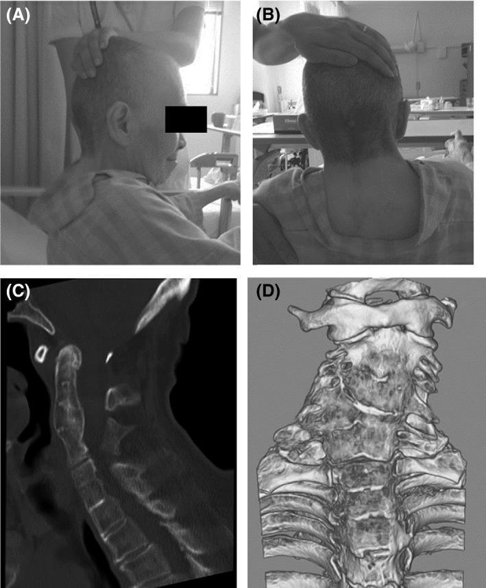
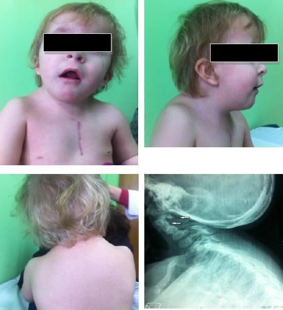
Radiological Findings
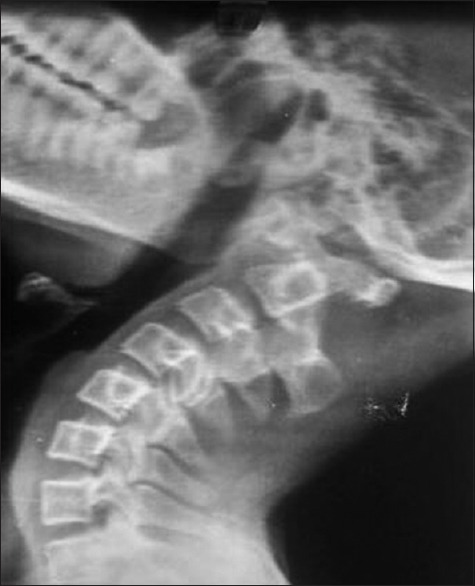
- Block vertebrae — absent disc spaces, fused vertebral bodies
- Shortened cervical spine
- "Wasp-waist" appearance of fused bodies (narrowing at the site of absent disc)
- Occipitalization of the atlas (in some)
- Congenital scoliosis / kyphosis
- Spinal cord compression
- Syringomyelia
- Arnold-Chiari malformation
- Cervical stenosis
Classification (Feil Classification)
| Type | Description |
|---|---|
| Type I | Massive fusion of all or most cervical and upper thoracic vertebrae into a single block |
| Type II | Fusion of one or two cervical interspaces, with hemivertebrae, occipitalization of atlas, or open laminae |
| Type III | Type I or II combined with lower thoracic or lumbar fusion |
Type II is the most common and clinically most significant due to associated instability at adjacent non-fused segments.
Associated Anomalies
Musculoskeletal:
| Anomaly | Frequency |
|---|---|
| Sprengel deformity (congenital elevation of scapula) | ~30–35% — most common musculoskeletal association |
| Omovertebral bone (osseous bar connecting scapula to cervical spine) | Associated with Sprengel |
| Congenital scoliosis / kyphosis | Common |
| Cervical ribs | Predispose to thoracic outlet syndrome |
| Hemivertebrae | Common |
Neurological:
- Mirror movements (synkinesia) — most characteristic neurological feature; involuntary mirroring of hand movements, especially of the hands; associated with abnormal clefts/division of spinal cord near cervicomedullary junction
- Syringomyelia / syringobulbia
- Cervical myelopathy — spinal stenosis from fused segments
- Atlantoaxial instability — risk of sudden cord compression
- Spinal cord compression — by stenosis or instability
Cardiac:
- Congenital heart defects (ventricular septal defect, ASD) — ~14% of patients
Renal/Urological:
- Renal anomalies — unilateral renal agenesis, horseshoe kidney (~35%)
Ear/Hearing:
- Sensorineural hearing loss — most common cranial nerve symptom
- External ear canal stenosis, microtia
Other:
- Cleft palate, bifid uvula, high arched palate
- Strabismus, nystagmus
- Wildervanck syndrome — KFS + Duane syndrome (retracted bulb, abducens palsy) + sensorineural deafness; predominantly in females
Neurological Complications
| Complication | Mechanism |
|---|---|
| Cervical myelopathy | Spinal stenosis at fused/adjacent levels |
| Radiculopathy | Nerve root compression |
| Atlantoaxial instability | Hypermobility at C1–C2 due to compensatory excessive motion |
| Syringomyelia | CSF flow obstruction |
| Thoracic outlet syndrome | Cervical ribs |
| Vertebrobasilar insufficiency | Vertebral artery compression |
The unfused adjacent segments bear abnormally increased motion and are prone to accelerated degeneration and instability — the most dangerous being instability at C1–C2 or the craniocervical junction.
Diagnosis
- Clinical: Classic triad (short neck, low hairline, limited movement)
- X-ray cervical spine: Block vertebrae, absence of disc spaces, scoliosis
- CT spine: Better bony detail, 3D reconstruction
- MRI: Neural structures, cord compression, syrinx, Chiari malformation
- Echocardiogram: Cardiac anomalies
- Renal ultrasound: Renal anomalies
- Audiometry: Hearing loss assessment
Management
Conservative:
- Activity restriction — contact sports and activities risking neck injury are contraindicated
- Cervical collar or orthosis — for instability
- Physiotherapy for range of motion
- Hearing aids
Surgical:
| Indication | Procedure |
|---|---|
| Cervical myelopathy / cord compression | Decompression (laminoplasty / laminectomy) ± fusion |
| Atlantoaxial instability | C1–C2 fusion (Magerl/Brooks/Gallie technique) |
| High-grade spondylolisthesis at adjacent segments | Stabilisation + fusion |
| Sprengel deformity | Woodward procedure — surgical repositioning of scapula |
| Congenital scoliosis | Corrective fusion |
Prognosis
- Many patients lead normal lives, especially those with limited fusion and no neurological compromise
- Risk of sudden neurological deterioration from even minor trauma due to atlantoaxial instability — activity counselling is critical
- Mirror movements and hearing loss do not worsen significantly
- Accelerated adjacent segment degeneration leads to progressive myelopathy in adulthood in some patients
- Regular follow-up with MRI surveillance recommended for high-risk types
Summary Points for Exam
| Feature | Key Fact |
|---|---|
| Cause | Failure of cervical somite segmentation, weeks 3–8 |
| Classic triad | Short neck + low hairline + restricted movement |
| Most common musculoskeletal association | Sprengel deformity (~30%) |
| Most common cranial nerve symptom | Hearing loss |
| Most characteristic neurological sign | Mirror movements (synkinesia) |
| Most dangerous complication | Atlantoaxial instability → cord compression |
| Diagnosis confirmed by | Radiographic fusion of ≥2 cervical vertebrae |
| Most common type | Feil Type II |
| Important warning | Avoid contact sports; minor trauma can be catastrophic |
Anatomy of lumbar vertebrae and special note on 5th lumbar vertebrae for 10ma
lumbar vertebra anatomy labeled diagram transverse process spinous process pedicle lamina
Anatomy of Lumbar Vertebrae — 10 Marks
Introduction
General Anatomy of a Lumbar Vertebra
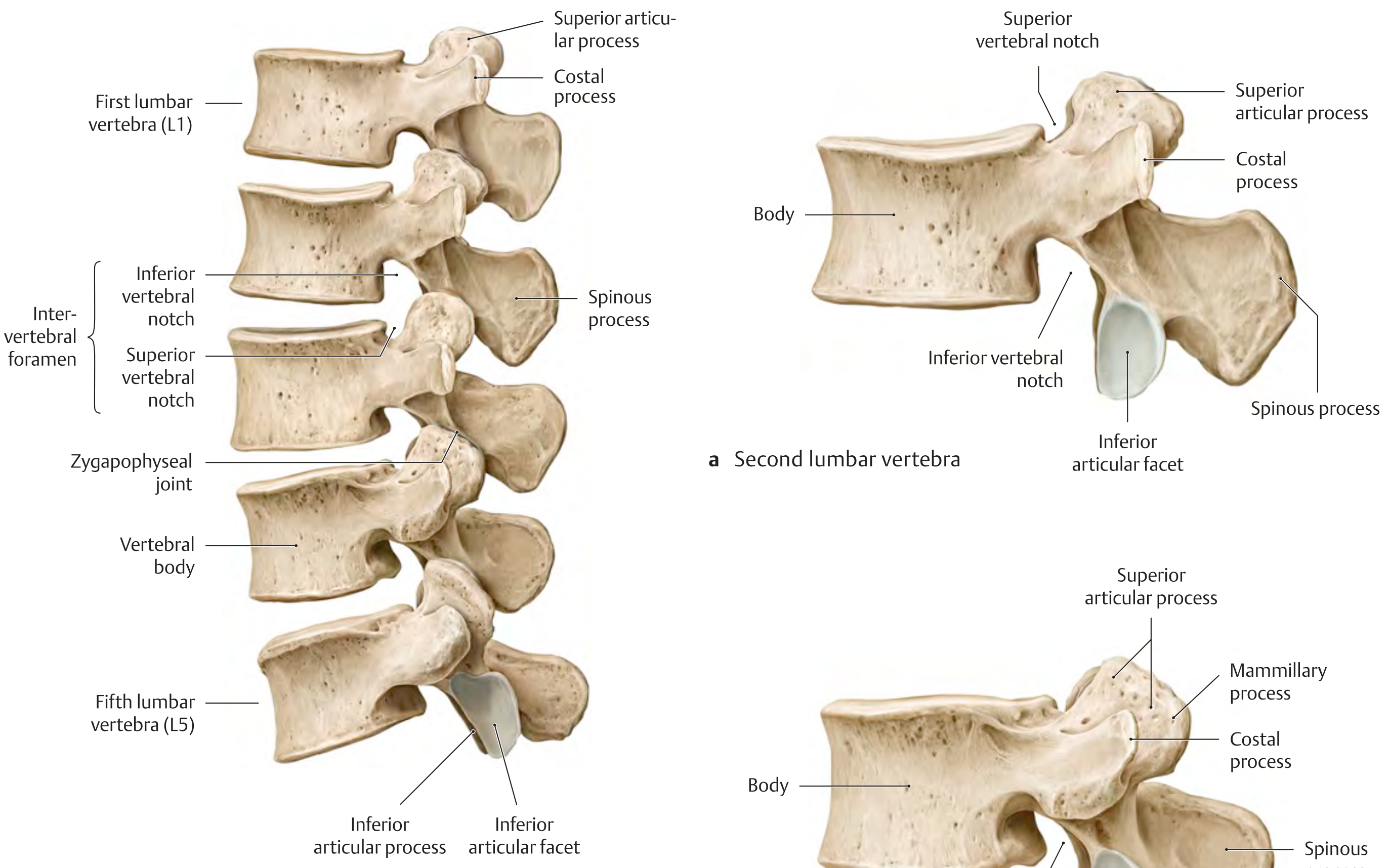
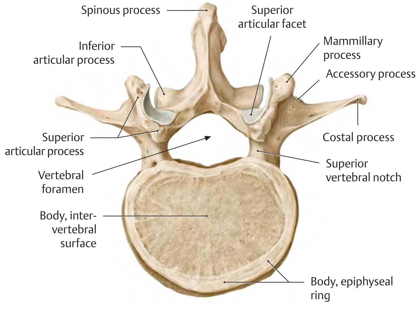
DIAGRAMS
1. Vertebral Body
- Largest of all vertebrae — reflects load-bearing function
- Transverse oval shape when viewed from above (wider side-to-side than front-to-back)
- Flat superior and inferior surfaces covered by hyaline cartilage end plates
- Epiphyseal ring (ring apophysis) = peripheral cortical rim of the end plate — fusion site for secondary ossification centres
- Cancellous (trabecular) bone internally; cortical shell externally
- Contains red bone marrow throughout life
- L5 body is wedge-shaped (taller anteriorly than posteriorly) — contributes to lumbosacral angle
2. Vertebral Arch (Neural Arch)
Pedicles
- Short, thick cylindrical bony pillars projecting posterolaterally from the posterosuperior surface of the vertebral body
- Have a superior vertebral notch (shallow) and inferior vertebral notch (deeper)
- Adjacent notches from consecutive vertebrae form the intervertebral foramen through which the spinal nerve exits
- Lumbar pedicles are the widest and strongest in the spine — the basis for pedicle screw fixation
Laminae
- Broad, flat plates that complete the neural arch posteriorly
- Unite in the midline to form the spinous process
- Site of ligamentum flavum attachment (between adjacent laminae)
- Laminectomy = removal of both laminae to decompress the canal
3. Vertebral (Spinal) Canal
- Almost triangular in shape (unlike cervical = triangular, thoracic = circular)
- Contains: spinal cord (only to L1–L2), cauda equina (below L1–L2), conus medullaris, filum terminale, meninges, CSF, spinal nerve roots
- Lumbar cistern = subarachnoid space containing CSF and cauda equina — site of lumbar puncture (L3–L4 or L4–L5 interspace)
4. Spinous Process
- Thick, broad, hatchet-shaped (quadrangular/rectangular when viewed laterally)
- Projects directly posteriorly (horizontally) — unlike thoracic spine where processes are angled inferiorly
- This horizontal orientation allows easy interspinous access for procedures
- Easily palpable along the midline
5. Costal Processes ("Transverse Processes")
- In lumbar vertebrae, the so-called "transverse processes" are actually costal (rib) processes — phylogenetically representing rudimentary ribs that have fused to the actual transverse processes
- Long and slender, projecting laterolaterally
- The true transverse process (accessory process) is a small pointed eminence at the base of each costal process — serves as attachment for muscles
- The costal process of L5 is the largest and widest of all
6. Articular Processes (Zygapophyses)
- Two superior articular processes project upward
- Two inferior articular processes project downward
- Adjacent superior and inferior articular processes form the zygapophyseal (facet) joints — synovial joints
- Orientation: Facets are vertical, nearly sagittal plane — this allows flexion/extension and lateral flexion but restricts rotation (unlike thoracic facets which permit rotation)
- Superior articular facets are concave, face medially and posteriorly
- Inferior articular facets are convex, face laterally and anteriorly
7. Mammillary Processes
- Small bony eminences on the posterior surface of the superior articular processes
- Serve as attachment points for intrinsic back muscles (multifidus, longissimus)
- Important surgical landmark
8. Accessory Processes
- Small projection at the base of each costal process posteriorly
- Represents the true transverse process
Ossification of Lumbar Vertebrae
| Centre | Timing |
|---|---|
| Primary centre — vertebral body | 9th–10th week intrauterine |
| Primary centres — vertebral arch (×2) | 8th–10th week intrauterine |
| Secondary — tip of spinous process | Puberty (16 years) |
| Secondary — tip of each transverse process | Puberty |
| Secondary — two annular epiphyses (superior and inferior) | Puberty; fuse ~25 years |
Intervertebral Disc
- Located between adjacent vertebral bodies
- Annulus fibrosus (outer fibrous ring) + nucleus pulposus (inner gelatinous core)
- The L4–L5 and L5–S1 discs bear the greatest mechanical stress → most common sites of disc herniation
- Disc height is greatest in the lumbar region (especially anteriorly) contributing to lumbar lordosis
Movements at Lumbar Spine
| Movement | Range | Notes |
|---|---|---|
| Flexion | ~60° | Greatest in lumbar spine |
| Extension | ~35° | |
| Lateral flexion | ~20° each side | |
| Rotation | ~5° each side | Significantly limited by sagittal facet orientation |
Special Note on the 5th Lumbar Vertebra (L5) — 10 Marks
Diagram
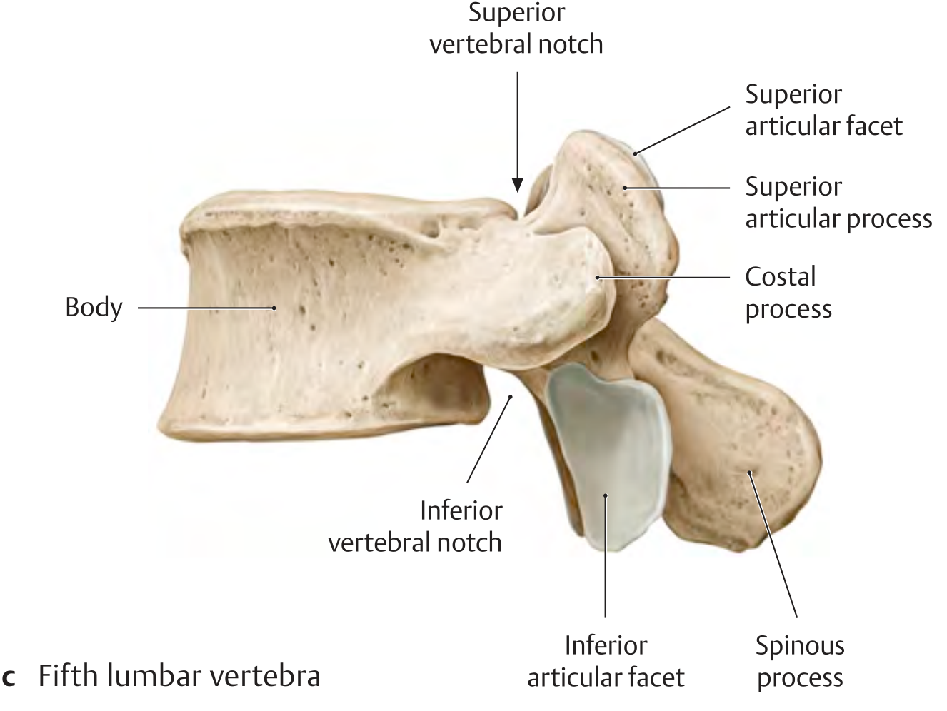
Why L5 is Unique
1. Wedge-Shaped Body
- L5 vertebral body is taller anteriorly than posteriorly (anteriorly wedged)
- This wedge shape is the primary contributor to the lumbosacral angle (~30° inclination at the L5–S1 junction)
- The sacrum continues this angle, contributing to lumbar lordosis
- This wedging also places L5 under a shear force — the body of L5 tends to slide anteriorly down the sacral slope → basis of spondylolisthesis at L5–S1
2. Costal (Transverse) Processes
- The costal processes of L5 are the largest, broadest, and most massive in the lumbar spine
- They are pyramidal in shape
- Their base blends directly into the pedicle and posterolateral body — not just the pedicle base as in L1–L4
- The broad base makes them difficult to separate from the pedicle during surgery
- They articulate/blend with the ala of the sacrum via the iliolumbar ligament (see below)
- Occasionally the transverse process of L5 may fuse with the sacrum — sacralization
3. Iliolumbar Ligament
- A powerful, thick ligament running from the tip and inferior surface of the L5 costal process to the iliac crest and ala of the sacrum
- Unique to L5 — no other lumbar vertebra has this ligament
- Functions:
- Restricts anterior sliding of L5 on the sacrum
- Limits flexion and extension at L5–S1
- Limits lateral flexion at L5–S1
- Key stabiliser of the lumbosacral junction
- Clinically: the iliolumbar ligament is commonly a source of low back and referred groin pain
4. Spinous Process
- The L5 spinous process is typically the smallest, shortest, and broadest in the lumbar spine
- Sometimes rudimentary or even absent
- This makes the L4–L5 and L4–L5–S1 interspinous spaces wider — facilitating epidural/lumbar puncture access
5. Intervertebral Foramen at L5–S1
- The L5–S1 intervertebral foramen is the smallest in the lumbar region
- Transmission: L5 nerve root exits through the L5–S1 foramen
- The L5 nerve root is also at risk from far-lateral disc herniations at L4–L5 (the L4 nerve root exits at L4–L5, so a far-lateral L4–L5 disc compresses L4; but an intracanal L4–L5 disc compresses L5)
- Due to the oblique exit angle of L5 nerve root and the narrowness of the foramen, L5 radiculopathy is the most common lumbar radiculopathy
6. Zygapophyseal (Facet) Joints at L5–S1
- The L5–S1 facet joints are the most coronally oriented of all lumbar facet joints
- This coronal orientation (unlike the more sagittal orientation of L1–L4 facets) permits more rotation at L5–S1 compared to other lumbar levels
- More coronal orientation → greater susceptibility to degenerative facet arthritis and facetogenic pain at this level
7. Lumbosacral Angle
- The angle between the long axis of L5 and the sacrum = lumbosacral angle (~130–145° in most individuals; approximately 30° inclination from horizontal at the sacral promontory)
- Increased lumbosacral angle → increased shear force on L5–S1 → predisposes to:
- Spondylolysis (stress fracture of the pars interarticularis)
- Spondylolisthesis (anterior slip of L5 on S1)
8. Pars Interarticularis at L5
- The pars interarticularis is the narrow bony bridge between the superior and inferior articular processes (isthmus of the lamina)
- L5 pars interarticularis is the most common site of spondylolysis — a fatigue stress fracture
- Bilateral pars fractures → isthmic spondylolisthesis at L5–S1 (most common type and level)
- The pars of L5 withstands the highest stress in the lumbar spine due to the shear forces at the lumbosacral junction
9. L5 Nerve Root
- Exits the dural sac at the L4–L5 level and travels in the lateral recess before exiting through the L5–S1 foramen
- Supplies:
- Motor: Extensor hallucis longus (great toe dorsiflexion — key muscle), tibialis anterior, toe extensors, hip abductors (gluteus medius)
- Sensory: Lateral calf, dorsum of foot, first web space
- Reflex: No reliable deep tendon reflex (the medial hamstring reflex may be affected)
- L5 radiculopathy presents as: foot drop, weak great toe extension, numbness over dorsum of foot/first web space
10. Variations of L5
| Variation | Description | Clinical Significance |
|---|---|---|
| Sacralization of L5 | Partial or complete fusion of L5 transverse process with sacrum / ilium | Alters biomechanics; causes asymmetrical stress; back pain; alters level counting |
| Lumbarization of S1 | S1 segment behaves as a 6th lumbar vertebra | Effectively creates 6 lumbar vertebrae; alters pelvic anatomy |
| Transitional vertebra | Incomplete sacralization or lumbarization (Bertolotti's syndrome) | Unilateral fusion → asymmetrical motion → accelerated degeneration on mobile side |
| Spina bifida occulta at L5 | Failure of laminar fusion posteriorly | Usually incidental; rarely symptomatic |
Summary Comparison: L5 vs. Typical Lumbar Vertebra
| Feature | Typical Lumbar (L1–L4) | L5 |
|---|---|---|
| Body shape | Roughly cylindrical | Wedge-shaped (taller anteriorly) |
| Costal processes | Slender, horizontal | Largest, broadest, pyramidal |
| Special ligament | None | Iliolumbar ligament to iliac crest |
| Spinous process | Thick, broad | Smallest, often rudimentary |
| Facet orientation | Sagittal | More coronal at L5–S1 |
| Pars fracture | Uncommon | Most common site of spondylolysis |
| Nerve root | Various | L5 root — most commonly involved in radiculopathy |
| Disc herniation | Any level | L5–S1 most common with L5 nerve root compression |
| Developmental anomaly | Rare | Sacralization / transitional vertebra |
Anatomy of lumbar vertebrae and special note on 5th lumbar vertebrae for 10 marks
What Was Already Provided:
- Vertebral body (transverse oval, large, cancellous core, epiphyseal ring)
- Pedicles (short, thick — basis for pedicle screw fixation)
- Laminae → vertebral canal (triangular, contains cauda equina below L1–L2)
- Spinous process (horizontal, hatchet-shaped — unlike thoracic)
- Costal processes (homologous to rudimentary ribs, not true transverse processes)
- Articular processes / facet joints (sagittal orientation — allows flexion, restricts rotation)
- Mammillary and accessory processes
- Ossification centres and timing
- Movements (flexion 60°, rotation only 5°)
- Wedge-shaped body → lumbosacral angle → shear forces
- Largest costal processes (pyramidal, fused to body + pedicle)
- Iliolumbar ligament (unique to L5)
- Smallest/most rudimentary spinous process
- Smallest intervertebral foramen at L5–S1
- More coronal facet orientation at L5–S1
- Pars interarticularis — most common site of spondylolysis
- L5 nerve root deficits (foot drop, first web space numbness)
- Variations: sacralization, lumbarization, Bertolotti's syndrome
Kindly give it again due to error its not showing
Anatomy of Lumbar Vertebrae — 10 Marks
Introduction
- No costal facets (no rib articulations)
- No transverse foramina (unlike cervical vertebrae)
- Largest vertebral bodies in the spine
Diagrams
Parts of a Typical Lumbar Vertebra
1. Vertebral Body
- Largest of all vertebral regions — designed for load bearing
- Transverse oval shape when viewed from above (wider side-to-side than front-to-back)
- Superior and inferior surfaces = flat end plates covered by hyaline cartilage
- Epiphyseal (ring) apophysis = peripheral cortical rim on each end plate — the strongest part of the end plate; site for cage placement in interbody fusion
- Interior = cancellous (trabecular) bone housing red bone marrow (throughout life)
- Outer cortical shell bears compressive loads
2. Pedicles
- Two short, thick, cylindrical bony pillars projecting posterolaterally from the posterosuperior aspect of the body
- Have a superior vertebral notch (shallow) and inferior vertebral notch (deep)
- Adjacent notches from consecutive vertebrae together form the intervertebral foramen
- Lumbar pedicles are the widest and strongest in the entire spine → basis of pedicle screw fixation in spinal surgery
- The pedicle is the critical corridor for surgical instrumentation
3. Laminae
- Broad, flat plates projecting posteromedially from the pedicles
- Unite in the midline to form the spinous process
- Inner surface lines the vertebral canal
- Ligamentum flavum attaches between adjacent laminae
- Laminectomy = bilateral removal of laminae → decompresses the neural canal
4. Vertebral (Spinal) Canal
- Almost triangular in shape (unlike the circular thoracic canal)
- Wider in lumbar region than thoracic — allows more surgical access
- Contains (below L1–L2): cauda equina, conus medullaris, filum terminale, meninges, CSF
- Lumbar cistern (L2–S2) = subarachnoid space containing CSF + cauda equina → site of lumbar puncture at L3–L4 or L4–L5
5. Spinous Process
- Thick, broad, quadrangular/hatchet-shaped when viewed laterally
- Projects directly posteriorly (horizontally) — unlike thoracic processes which angle inferiorly
- This horizontal orientation creates wide interspinous spaces allowing easier access for epidural, lumbar puncture, and interspinous device insertion
- Palpable along the midline as prominent bony landmarks
6. Costal Processes (= "Transverse Processes")
- The lumbar "transverse processes" are actually costal (rib) processes — phylogenetically they represent rudimentary ribs that have fused to the true transverse processes
- Long, slender, project laterally
- The true transverse process (accessory process) = a small pointed bony eminence at the base of each costal process — site of muscle attachment
- Costal processes serve as attachment for:
- Quadratus lumborum
- Intertransverse muscles
- Iliolumbar ligament (at L5 especially)
- Psoas major (anterior surface)
7. Articular Processes (Zygapophyses)
- Two superior articular processes project upward; two inferior articular processes project downward
- Adjacent superior + inferior articular processes form zygapophyseal (facet) joints — true synovial joints
- Facet orientation in lumbar spine: nearly sagittal (vertical)
- Superior articular facets = slightly concave, face medially and posteriorly
- Inferior articular facets = slightly convex, face laterally and anteriorly
- This sagittal orientation allows flexion/extension and lateral flexion but restricts rotation (in contrast to thoracic vertebrae)
8. Mammillary Processes
- Small bony eminences on the posterior surface of each superior articular process
- Serve as origins/insertions for intrinsic back muscles (multifidus, longissimus)
- Important surgical landmark
9. Accessory Processes
- Small projection at the posteroinferior base of each costal process
- Represents the true homologue of the transverse process of other vertebrae
Intervertebral Disc
- Annulus fibrosus (outer fibrous ring) + nucleus pulposus (inner gelatinous core)
- Lumbar discs are the thickest in the spine
- L4–L5 and L5–S1 are most common sites of disc herniation due to maximum mechanical stress
- Disc height contributes to lumbar lordosis
Joints of the Lumbar Spine
| Joint | Type | Between |
|---|---|---|
| Intervertebral disc joint | Secondary cartilaginous (symphysis) | Adjacent vertebral bodies |
| Zygapophyseal (facet) joint | Synovial plane joint | Articular processes of adjacent vertebrae |
| Uncovertebral joints | Not present in lumbar (only cervical) | — |
Movements of the Lumbar Spine
| Movement | Range | Notes |
|---|---|---|
| Flexion | ~60° | Greatest range in lumbar spine |
| Extension | ~35° | |
| Lateral flexion | ~20° each side | |
| Rotation | ~5° each side | Severely limited by sagittal facet orientation |
Ossification
| Centre | Timing |
|---|---|
| Primary — vertebral body | 9th–10th week intrauterine |
| Primary — each half of vertebral arch (×2) | 8th–10th week intrauterine |
| Secondary — tip of spinous process | Puberty (~16 years) |
| Secondary — tip of each transverse process | Puberty |
| Secondary — 2 annular epiphyses (superior + inferior end plates) | Puberty; fuse ~25 years |
Special Note on the 5th Lumbar Vertebra (L5)
Diagram
1. Wedge-Shaped Vertebral Body
- The body of L5 is taller anteriorly than posteriorly — anteriorly wedged
- This wedging is the primary structural contributor to the lumbosacral angle (~30° inclination)
- The sacrum continues this angulation → together they create lumbar lordosis
- The wedged body places L5 under significant anterior shear force — the body tends to slide forwards and downwards along the sacral slope
- This is the mechanical basis for spondylolisthesis at L5–S1
2. Costal (Transverse) Processes — Largest in the Spine
- The costal processes of L5 are the largest, broadest, and most massive of all lumbar vertebrae
- They are pyramidal/triangular in shape
- Their base blends directly with both the pedicle and the posterolateral body (unlike L1–L4 where they arise mainly from the pedicle)
- Provide broad attachment for the iliolumbar ligament (see below)
- May fuse with the sacrum/ilium → sacralization
3. Iliolumbar Ligament — Unique to L5
- A powerful thick ligament running from the costal process of L5 (and to a lesser extent L4) to the iliac crest and ala of the sacrum
- No other lumbar vertebra has this ligament
- Functions:
- Resists anterior sliding of L5 on the sacrum (counters shear force)
- Limits flexion, extension, and lateral flexion at L5–S1
- Primary stabiliser of the lumbosacral junction
- Clinically: source of chronic low back pain and referred groin/thigh pain
4. Spinous Process — Smallest
- The spinous process of L5 is the smallest, shortest, and often most rudimentary in the lumbar spine
- Sometimes bifid or even absent
- Creates the widest interspinous space at L4–L5 and L5–S1 → easiest access for lumbar puncture and epidural anaesthesia
5. Pars Interarticularis — Most Vulnerable Site
- The pars interarticularis = narrow bony isthmus between the superior and inferior articular processes (within the lamina)
- L5 pars interarticularis withstands the highest mechanical stress in the spine due to:
- Shear forces from the lumbosacral angle
- Repetitive hyperextension (gymnastics, fast bowling, weightlifting)
- Spondylolysis = fatigue stress fracture through the pars interarticularis → most common at L5 (85–95% of cases)
- Bilateral spondylolysis → the vertebral body separates from its posterior arch → isthmic spondylolisthesis at L5–S1 (most common type and level)
6. Facet Joints at L5–S1 — Most Coronal
- The L5–S1 facet joints are the most coronally oriented in the lumbar spine
- Coronal orientation (compared to more sagittal L1–L4):
- Permits more rotation than upper lumbar levels
- More prone to degenerative osteoarthritis and facetogenic pain
- Provides resistance to anterior spondylolisthesis
7. Intervertebral Foramen at L5–S1
- The L5–S1 intervertebral foramen is the smallest in the lumbar region
- The L5 nerve root exits through this foramen
- Due to the narrow foramen + large disc + osteophytes: L5 radiculopathy is extremely common
8. L5 Nerve Root — Clinical Importance
| Feature | L5 Root |
|---|---|
| Exit level | L5–S1 intervertebral foramen |
| Motor supply | Extensor hallucis longus (great toe extension — key), tibialis anterior, toe extensors, gluteus medius (hip abduction) |
| Sensory supply | Lateral calf, dorsum of foot, first web space between 1st and 2nd toes |
| Reflex | No reliable reflex (medial hamstring, inconsistent) |
| Compression sign | Disc herniation at L4–L5 (compresses traversing L5 root) |
| Clinical presentation | Foot drop, weak great toe extension, numbness first web space |
9. Developmental Variations of L5
| Variation | Description | Significance |
|---|---|---|
| Sacralization | Partial/complete fusion of L5 transverse process with sacrum/ilium | Alters biomechanics; produces asymmetric stress; causes low back pain; changes level counting (important pre-surgically) |
| Lumbarization of S1 | S1 behaves as a 6th lumbar vertebra | Creates "6 lumbar vertebrae"; alters pelvic anatomy |
| Transitional vertebra (Bertolotti's syndrome) | Unilateral partial sacralization | Asymmetric motion → accelerated degeneration on the mobile side; low back ± groin pain |
| Spina bifida occulta | Failure of posterior arch fusion | Common, usually incidental finding |
Summary Comparison: L5 vs. Typical Lumbar Vertebra (L1–L4)
| Feature | L1–L4 | L5 |
|---|---|---|
| Body shape | Roughly cylindrical | Wedge-shaped (taller anteriorly) |
| Costal processes | Slender, horizontal | Largest, pyramidal, massive |
| Special ligament | None | Iliolumbar ligament |
| Spinous process | Thick and broad | Smallest, often rudimentary |
| Facet orientation | Sagittal | More coronal at L5–S1 |
| Pars fracture | Uncommon | Most common site (spondylolysis) |
| Nerve root | L1–L4 respectively | L5 root — most commonly symptomatic |
| Most common disc level | — | L5–S1 (with L4–L5 a close second) |
| Developmental anomaly | Rare | Sacralization/transitional vertebra |
Ligamentotaxis explain in detail for 10 marks question