
Position and movement of the human body
anatomical position planes of the body
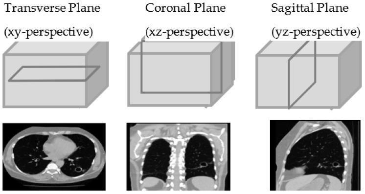
This diagnostic imaging illustration demonstrates the three primary anatomical planes of the human body using Computed Tomography (CT) of the chest. The top row features 3D diagrams of a rectangular volume representing the chest, with an intersecting plane highlighting the orientation for each perspective: Transverse (XY), Coronal (XZ), and Sagittal (YZ). Below these diagrams are corresponding 2D CT slices. The Transverse plane shows a horizontal cross-section of the thorax, displaying the bilateral lungs (dark areas), the central mediastinum including the heart, and the vertebral body. A focal cavitary lesion or nodule is visible in the left lung. The Coronal plane provides a frontal view, illustrating the vertical extent of the lungs, the diaphragm, and the spinal column. The Sagittal plane presents a lateral profile, showing the anterior-posterior depth of the lung, the rib cage, and the curvature of the diaphragm. These views are utilized for volumetric analysis and 3D reconstruction in clinical radiology, particularly for characterizing pulmonary pathology.
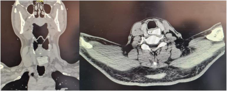
This diagnostic image displays a non-contrast CT scan of the neck in two planes: coronal (left) and axial (right). The primary pathology is a radiopaque, rectangular foreign body approximately 20 x 25 mm lodged within the cervical esophagus. In the coronal view, the high-density object is positioned inferior to the laryngeal structures and hyoid bone, within the upper third of the esophagus. In the axial view, the foreign body is clearly visualized posteriorly to the trachea and anteriorly to the vertebral body, demonstrating its intraluminal position in the esophageal space. Key anatomical landmarks visible include the mandible, cervical vertebrae, trachea with its air-filled lumen, and surrounding soft tissues. This imaging is clinically significant for diagnosing esophageal foreign body obstruction and assessing for complications such as perforation or deviation of adjacent structures. It serves as an educational example of radiological identification of non-biologic esophageal foreign bodies in an emergency or surgical context.
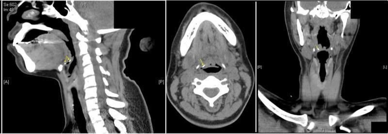
A three-panel diagnostic Computed Tomography (CT) scan of the neck and upper aerodigestive tract, presented in sagittal (left), axial (center), and coronal (right) planes. The images demonstrate a radiopaque, curvilinear foreign body, consistent with a fish bone, measuring approximately 2 cm in length. Yellow arrows indicate the object's precise location within the right vallecula, the anatomical space between the base of the tongue and the epiglottis. The sagittal view reveals the object's curved morphology anterior to the epiglottis; the axial view shows its position lateral to the midline near the tongue base; and the coronal view confirms its right-sided orientation within the pharyngeal space. Visible anatomical landmarks include the mandible, hyoid bone, cervical vertebrae, and airway. This imaging panel is used in otolaryngology and emergency medicine to teach the radiographic identification of ingested foreign bodies and their potential for airway obstruction or local tissue injury.
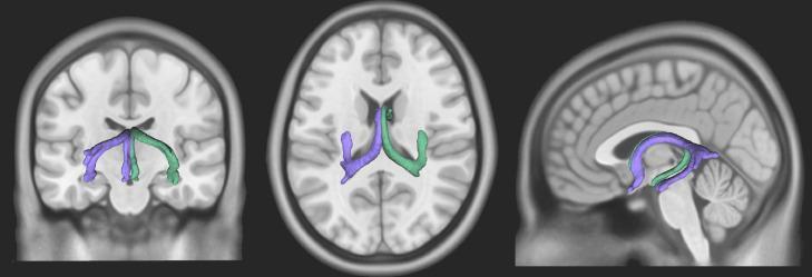
This diagnostic visualization presents a three-dimensional reconstruction of the human fornix superimposed on T1-weighted magnetic resonance imaging (MRI) slices. The graphic displays the fornix in three standard anatomical planes: coronal (left), axial (center), and sagittal (right). The fornix, a key white matter bundle of the limbic system, is color-coded to differentiate bilateral symmetric bands (purple and green). In the sagittal view, the characteristic C-shaped arch is highly visible, demonstrating its position inferior to the corpus callosum and superior to the thalamus. The axial and coronal views highlight its spatial relationship to the ventricular system and its course from the hippocampus toward the diencephalon and basal forebrain. This neuroimaging representation is used for educational purposes to demonstrate the 3D trajectory of limbic pathways, including the columns, body, and crura of the fornix, which are essential for memory formation and cognitive function. The visualization was generated using DSI Studio software based on healthy adult anatomy.
body movements flexion extension abduction adduction rotation anatomy
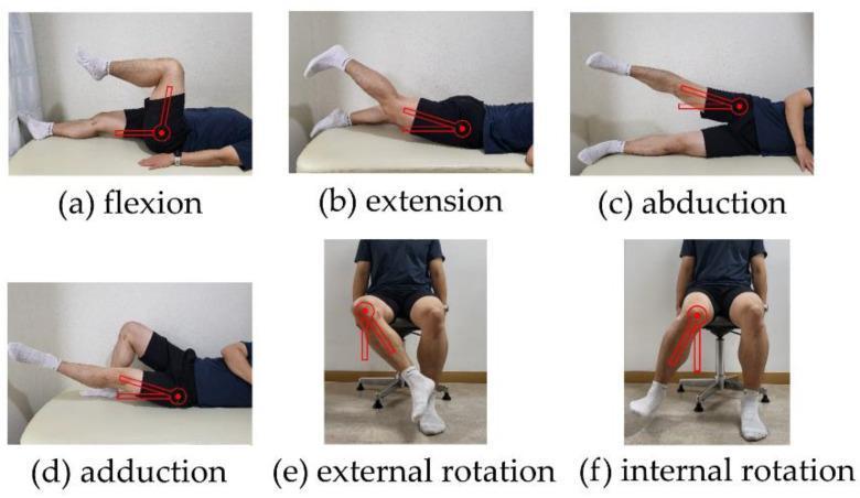
A multi-panel series of clinical photographs illustrating the standard assessment of hip joint Range of Motion (ROM). The panels are labeled (a) through (f) and demonstrate specific movements with goniometric overlays indicated by red circular axes and linear vectors. (a) Flexion: Subject in supine position with the knee flexed toward the chest. (b) Extension: Subject in prone position with the lower limb extended posteriorly. (c) Abduction: Subject in a side-lying (lateral decubitus) position with the limb elevated away from the midline. (d) Adduction: Subject in side-lying position with the limb crossing the midline. (e) External rotation and (f) Internal rotation: Subject in a seated position with the hip and knee at 90-degree flexion, showing transverse plane movement of the femur relative to the knee joint axis. The red overlays represent the placement of a goniometer, with the axis centered on the greater trochanter or the knee (for rotation), used to measure angular displacement. This visual guide is intended for clinical physical examination, rehabilitation, and the assessment of conditions like adhesive hip capsulitis or femoroacetabular impingement.
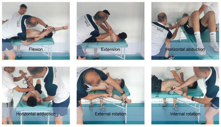
A series of clinical photographs illustrating the systematic assessment of passive shoulder range of motion (ROM) in a young athlete. The figure contains six individual panels, each demonstrating a specific movement: flexion, extension, horizontal abduction, horizontal adduction, external rotation, and internal rotation. The patient is positioned on a padded examination table in supine (for flexion, rotation, and horizontal movements) or prone (for extension) positions. For each measurement, a clinical inclinometer with a circular dial is strapped to the patient's distal forearm or humerus to objectively quantify the degrees of motion. An examiner is shown performing manual stabilization of the scapula or torso while moving the limb to its maximum passive expression. This setup is characteristic of the ROM-SPORT II battery used in sports medicine and physical therapy to screen for musculoskeletal risk factors such as glenohumeral internal rotation deficit (GIRD). The clinical significance lies in identifying athletes at increased risk for shoulder pain or injury by comparing values against established cut-off points.
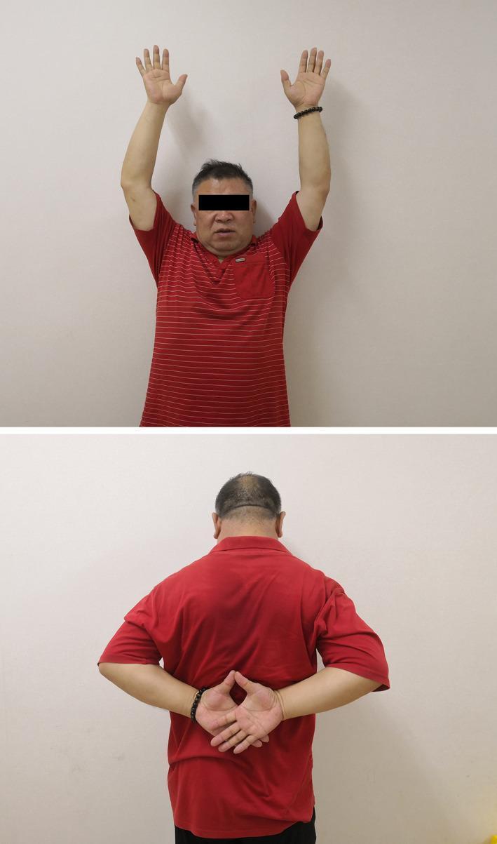
This clinical photograph consists of two panels illustrating the postoperative functional outcome and range of motion (ROM) in a patient following surgical repair of an acromioclavicular joint (ACJ) dislocation. The upper panel shows an anterior view of the patient demonstrating full bilateral shoulder abduction and flexion with both arms raised symmetrically overhead. The elbows are in full extension, and the hands are open with fingers extended, indicating unimpaired upward mobility. The lower panel shows a posterior view of the patient demonstrating internal rotation and adduction of the shoulders. The patient has successfully placed both hands behind the back with the fingers interlaced, a position often used in the Apley Scratch Test to assess functional internal rotation. The images highlight the successful restoration of joint stability and mobility after double‐loaded suture anchor reconstruction of the coracoclavicular (CC) ligaments and ACJ augmentation, showing no evidence of residual pain or mechanical restriction during these movements.
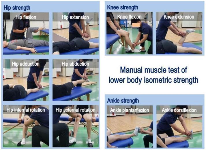
A composite of clinical photographs demonstrating manual muscle testing (MMT) for lower extremity isometric strength. The image is organized into three sections: hip, knee, and ankle strength. The hip section illustrates six movements: flexion (supine), extension (prone), adduction (side-lying), abduction (side-lying), and internal/external rotation (seated). The knee section shows flexion (prone) and extension (seated). The ankle section demonstrates plantarflexion and dorsiflexion (supine). In each frame, an examiner is shown applying manual resistance or using a hand-held dynamometer against the patient's limb to assess maximal isometric force. The photos emphasize proper patient positioning, limb stabilization, and examiner hand placement at specific anatomical landmarks (e.g., distal femur for hip flexion, proximal to the malleoli for hip abduction/adduction, and metatarsal heads for ankle movements). This visual guide is intended for clinical education in physical therapy, sports medicine, and orthopedic rehabilitation to standardize muscle strength assessment protocols.
standard anatomical position directional terms superior inferior medial lateral
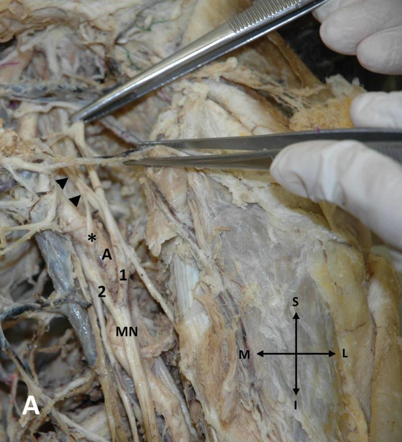
This clinical photograph captures a detailed anatomical dissection of the left axillary region in a cadaver, specifically highlighting an anatomical variation of the brachial plexus. The image displays the axillary artery (A) and the formation of the median nerve (MN). A key anatomical variant is demonstrated: an additional lateral root of the median nerve (marked with an asterisk) originating from the anterior division of the middle trunk (indicated by arrowheads). This additional root is seen crossing anterior to the axillary artery to fuse with the medial root (2), forming a distinct neural loop. The standard lateral root (1) is also visible, contributing to the main trunk of the median nerve distal to the variant fusion. Directional indicators (S: Superior, I: Inferior, M: Medial, L: Lateral) provide orientation for the neurovascular structures. Surgical forceps are used to retract and highlight the specific nerves and their junctions. This image is an important educational resource for understanding neurovascular variations in the axilla, which have significant clinical implications for surgical approaches and regional anesthesia of the upper limb.
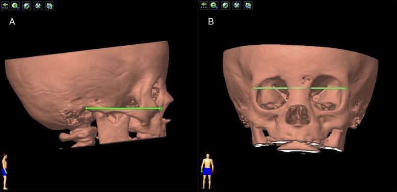
This diagnostic image displays a three-dimensional CT volume rendering of a human skull, specifically used to define standardized anatomical positioning for orbital analysis. Panel A illustrates the 'Standard Lateral Position.' A horizontal green line represents Reid’s baseline, connecting the inferior orbital margin (Orbitale point) to the superior margin of the external acoustic meatus (Auriculare point). This orientation ensures the mandibles are aligned and the cranial base is level. Panel B illustrates the 'Standard Frontal Position' after a 90-degree rotation from the lateral view. A second horizontal green line is drawn between the bilateral frontozygomatic sutures to ensure a symmetrical, standardized anterior-posterior orientation. These reference planes are critical in ophthalmology and radiology for consistent volumetric measurement of the bony orbit and localization of intraorbital pathologies, such as cysts or globe displacements. The rendering provides a clear view of the orbital rims, nasal cavity, and calvarium in a pediatric-appearing skull.
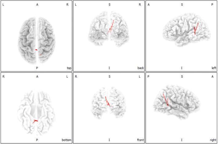
This diagnostic visualization consists of six 3D neuroimaging renderings of the human brain, illustrating functional connectivity data. The images are presented in six standard anatomical orientations: top (superior), bottom (inferior), back (posterior), front (anterior), left lateral, and right lateral views. Each view is labeled with directional markers: L (left), R (right), A (anterior), P (posterior), S (superior), and I (inferior) to maintain spatial context. The cortical surface is depicted in light gray, showing clearly defined gyri and sulci. Superimposed on these renderings are red curvilinear lines representing statistically significant (p < .05) increased functional connections in chronic tinnitus patients. These connections, identified via lagged phase synchronization analysis, map specifically to pathways between the parahippocampus gyrus (Brodmann areas 21 and 22) and the posterior cingulate cortex (BA 18) as well as the precuneus (BA 28). The visualization demonstrates localized enhancements in functional synchronization within the medial temporal and posteromedial parietal regions associated with auditory and cognitive processing.
types of synovial joints hinge pivot ball socket plane saddle
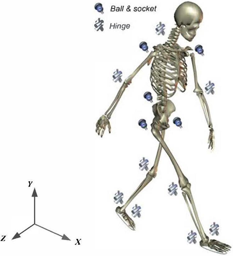
Anatomical diagram presenting a three-dimensional whole-body skeletal model used for biomechanical analysis and gait prediction. The model is divided into 13 rigid segments: head, torso, pelvis, bilateral upper arms, forearms, thighs, shanks, and feet. These segments are interconnected by 12 joints, categorized by their mechanical degrees of freedom (DoF). Ball-and-socket joints (3 DoFs) are indicated at the shoulders, hips, and waist, while hinge joints (1 DoF) are located at the neck, elbows, and knees. The ankle is modeled as a universal joint (2 DoFs). A global Cartesian coordinate system is provided in the lower-left corner: the X-axis represents the progression direction (sagittal plane), the Y-axis points vertically upwards (longitudinal axis), and the Z-axis represents the lateral direction (frontal plane). This schematic illustrates the multi-segment articulated system and the kinematic constraints necessary for simulating human movement and calculating ground reaction forces and joint torques in physical therapy or orthopedic research.
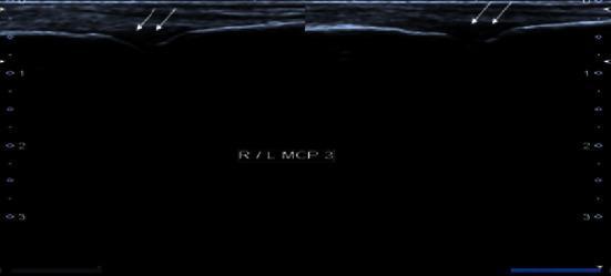
This grayscale ultrasound image displays a bilateral comparative view of the third metacarpophalangeal (MCP) joints in a transverse or longitudinal-oblique plane. The scan focuses on the dorsal aspect of the joints to evaluate the synovial space. White arrows in both the right (R) and left (L) panels highlight localized areas of hypoechoic tissue expansion within the joint recesses, signifying moderate synovial thickening. The echogenicity of this thickened synovium is relatively low (hypoechoic) compared to the overlying subcutaneous tissues and the hyperechoic surface of the underlying metacarpal bone. The presentation is classically consistent with Grade 2 synovitis, a key finding in inflammatory arthropathies such as rheumatoid arthritis or post-viral inflammatory syndromes. The bone cortex appears smooth without visible erosions, and the lack of color flow suggests a low-grade or non-hyperemic state if Power Doppler was applied. This image is used to teach MSK ultrasound findings for diagnosing active joint inflammation in clinical rheumatology.
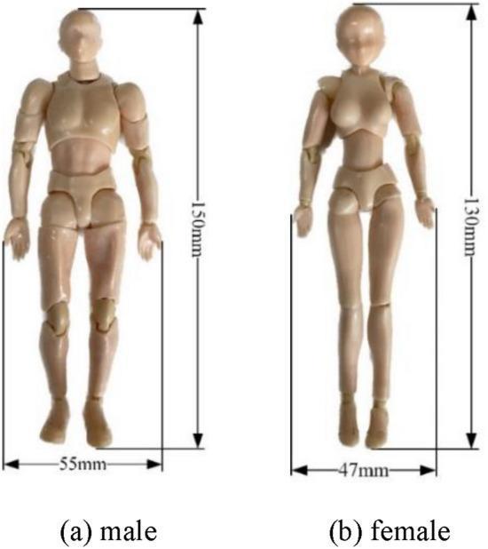
This educational image depicts two articulated anatomical human models used for simulated medical research, specifically for 3D point cloud acquisition and pose recognition. The image features a side-by-side comparison of a 'male' model (Figure a) and a 'female' model (Figure b). Both models exhibit visible ball-and-socket and hinge joints at the neck, shoulders, elbows, wrists, hips, knees, and ankles, allowing for posable clinical scenarios. The male model is characterized by a broader torso and a height of 150 mm with a base width of 55 mm. The female model displays narrower shoulders and a more tapered waist, with a height of 130 mm and a base width of 47 mm. These 1:12 scale plastic-like beige models serve as surrogates in experimental setups to analyze body mechanics, such as swimming postures or drowning detection algorithms, providing standardized anatomical references for diagnostic technology training.
Position and Movement of the Human Body
1. Standard Anatomical Position
- Forensic Anthropology: A Comprehensive Introduction, p. 108
- Gray's Anatomy for Students, p. 20
2. Anatomical Planes
| Plane | Orientation | Divides Body Into |
|---|---|---|
| Sagittal | Vertical, front to back | Left and right halves |
| Coronal (Frontal) | Vertical, side to side | Anterior (front) and posterior (back) |
| Transverse (Horizontal) | Horizontal | Superior (upper) and inferior (lower) |
3. Directional Terminology
| Term | Meaning |
|---|---|
| Anterior / Ventral | Front / belly side |
| Posterior / Dorsal | Back |
| Superior / Cranial | Toward the head |
| Inferior / Caudal | Away from the head |
| Medial | Toward the midline |
| Lateral | Away from the midline |
| Proximal | Nearest the trunk (used for limbs) |
| Distal | Farthest from the trunk |
- Forensic Anthropology: A Comprehensive Introduction, p. 108
4. Body Positions (Clinical)
| Position | Description |
|---|---|
| Supine | Lying on the back, face upward |
| Prone | Lying face downward |
| Lateral recumbent | Lying on one side |
| Erect/Upright | Standing, as in standard anatomical position |
5. Joints and Their Types
Synovial Joints (freely movable)
| Joint Type | Axes | Movements | Example |
|---|---|---|---|
| Plane (Gliding) | Non-axial | Sliding/gliding | Acromioclavicular joint |
| Hinge | Uniaxial | Flexion and extension | Elbow (humero-ulnar) |
| Pivot | Uniaxial (longitudinal) | Rotation | Atlanto-axial joint |
| Bicondylar | Mainly uniaxial | Flexion/extension + limited rotation | Knee joint |
| Condylar (Ellipsoid) | Biaxial | Flexion, extension, abduction, adduction, circumduction | Wrist joint |
| Saddle | Biaxial | Flexion, extension, abduction, adduction, circumduction | Carpometacarpal joint of thumb |
| Ball and Socket | Multiaxial | All of the above + full rotation | Hip and shoulder joints |
- Gray's Anatomy for Students, p. 35
Solid Joints (limited movement)
- Fibrous joints: Sutures (skull), gomphoses (teeth), syndesmoses
- Cartilaginous joints: Primary (growth plates) and secondary (symphyses, e.g., pubic symphysis, intervertebral discs)
6. Movements of the Body
| Movement | Description |
|---|---|
| Flexion | Forward/anterior movement of a trunk or limb; decreases the angle between parts |
| Extension | Backward/posterior movement; increases the angle between parts |
| Lateral flexion | Bending the head or trunk to either side |
| Abduction | Movement away from the midline of the body |
| Adduction | Movement toward the midline of the body |
| Internal rotation | Rotation of a limb toward the midline |
| External rotation | Rotation of a limb away from the midline |
| Circumduction | Combination of flexion, abduction, extension, and adduction (cone-shaped movement) - without rotation |
| Supination | Forearm movement so the palm faces anteriorly (upward) |
| Pronation | Forearm movement so the palm faces posteriorly (downward) |
| Inversion | Foot movement directing the sole medially |
| Eversion | Foot movement directing the sole laterally |
| Retraction | Backward movement of the head, jaw, or shoulders |
| Protraction | Forward movement of the head, jaw, or shoulders |
- Bailey and Love's Short Practice of Surgery, Table 35.3
7. Normal Ranges of Motion (Examples)
- Flexion: 100-135°
- Extension: 0-15° to 30°
- Abduction: 40°
- Adduction: 30°
- Internal rotation: 30-40°
- External rotation: 40-60°
- Abduction: Deltoid + supraspinatus
- Adduction: Latissimus dorsi, pectoralis major, teres major
- Forward flexion: Pectoralis major, anterior deltoid, biceps
- Extension: Latissimus dorsi
- Internal rotation: Subscapularis, teres major
- External rotation: Infraspinatus, teres minor
8. Muscle Power Grading (MRC Scale)
| Grade | Description |
|---|---|
| 0 | No movement |
| 1 | Flicker of movement |
| 2 | Movement with gravity eliminated |
| 3 | Movement against gravity only |
| 4 | Movement against resistance (reduced) |
| 5 | Normal power |
- Bailey and Love's Short Practice of Surgery, Table 35.4
Summary
- Positional reference - standard anatomical position and directional terms anchor all descriptions
- Structural basis - the type of joint determines what movements are possible (a hinge joint cannot rotate; a ball-and-socket joint can do everything)
- Movement terminology - a precise shared vocabulary (flexion, abduction, supination, etc.) allows clinicians and anatomists to communicate without ambiguity