
write origin insertion nerve supply action function and diagram of each muscle Transverse abdominis Multifidus Longus coli nd other cervical region ( deep muscles )
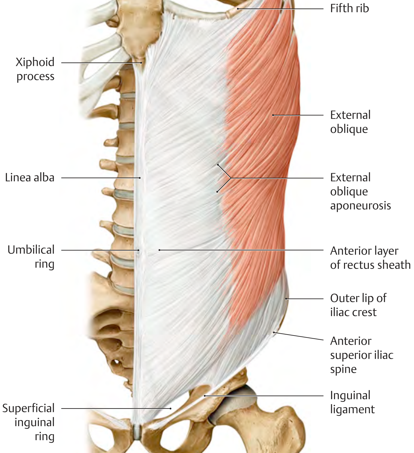
transverse abdominis muscle anatomy origin insertion
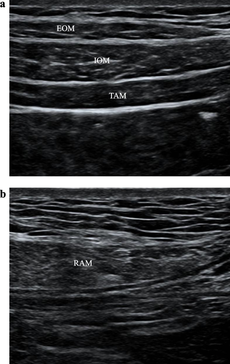
This diagnostic image consists of two high-frequency ultrasound panels (a and b) illustrating the anatomy of the anterior and lateral abdominal wall for regional anesthesia planning. Panel A demonstrates a transverse view of the lateral abdominal wall, showing three distinct muscle layers separated by hyperechoic fascial planes: the superficial external oblique muscle (EOM), the middle internal oblique muscle (IOM), and the deep transversus abdominis muscle (TAM). Below the TAM, a prominent hyperechoic line marks the transversus abdominis plane (TAP), a key landmark for TAP blocks. Panel B displays a transverse view of the rectus abdominis muscle (RAM), characterized by a striated, heterogeneous echotexture with visible internal fascial echoes. The image shows the interface between the RAM and the posterior rectus sheath, which is the target area for a rectus sheath block (RSB). Both images serve as educational references for identifying ultrasound-guided needle insertion sites for postoperative analgesia in abdominal surgery.
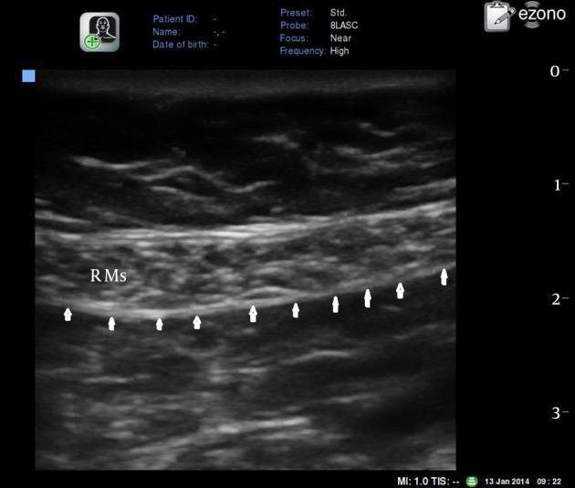
A transverse grayscale diagnostic ultrasound image of the anterior abdominal wall, specifically focusing on the rectus abdominis muscle (RMs) for clinical anatomy or procedural guidance. The imaging modality utilizes a high-frequency linear array probe with a 'near' focus, set to a depth of approximately 3-4 cm. The rectus abdominis muscle appears as a relatively hypoechoic, spindle-shaped structure with internal striated echotexture characteristic of skeletal muscle. Directly deep to the RMs, a distinct, continuous hyperechoic (bright white) horizontal line is identified by several small white arrows, representing the posterior rectus sheath. This anatomical landmark is crucial for identifying the plane for a Rectus Sheath Block (RSB). The image provides clear visualization of the relationship between the muscle belly and the underlying fascial plane, which is essential for regional anesthesia and pain management in surgical procedures involving the midline or umbilical region.
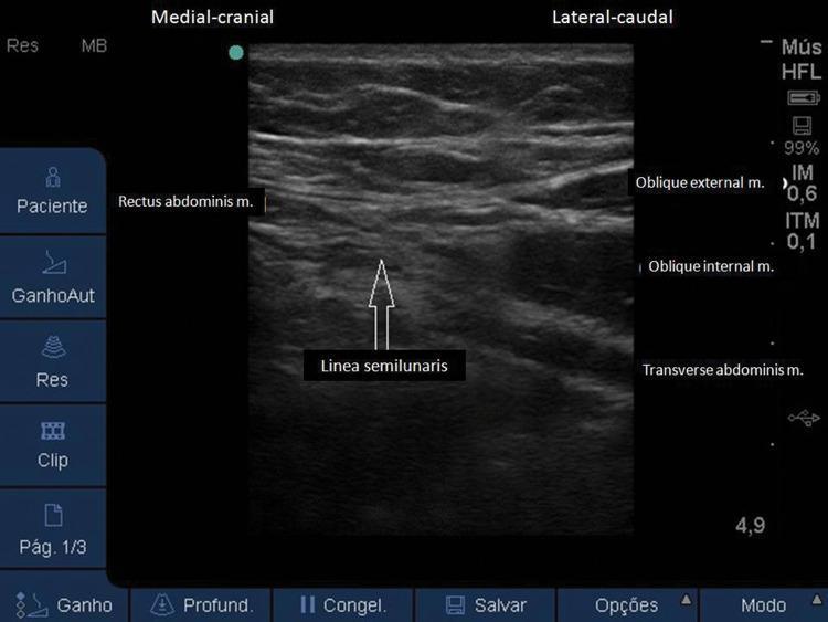
A diagnostic ultrasound image of the anterolateral abdominal wall, demonstrating the musculofascial anatomy in a transverse view. The image illustrates the transition between the medial and lateral abdominal muscle groups. On the left (medial-cranial aspect), the rectus abdominis muscle is identified by its characteristic fusiform shape. Centrally, an arrow points to the linea semilunaris, which represents the aponeurotic transition zone where the lateral abdominal muscles meet the rectus sheath. To the right (lateral-caudal aspect), three distinct muscular layers are visualized from superficial to deep: the external oblique muscle, the internal oblique muscle (often the most prominent layer), and the transverse abdominis muscle. These hypoechoic muscle layers are separated by hyperechoic fascial planes. This imaging is clinically significant for performing ultrasound-guided regional anesthesia, such as the Transversus Abdominis Plane (TAP) block or rectus sheath block, by identifying the specific intermuscular planes for anesthetic injection.
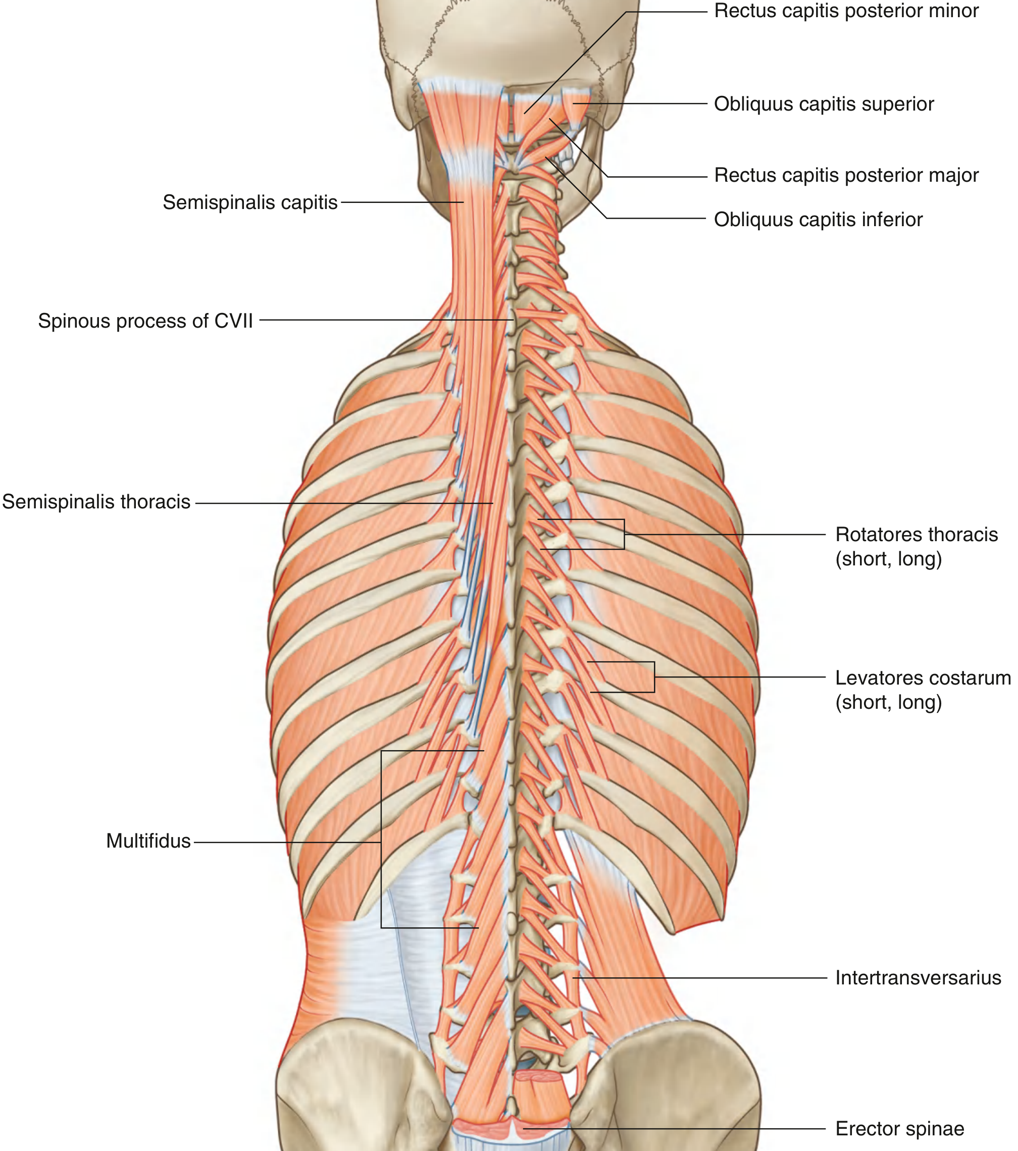
multifidus muscle anatomy spine
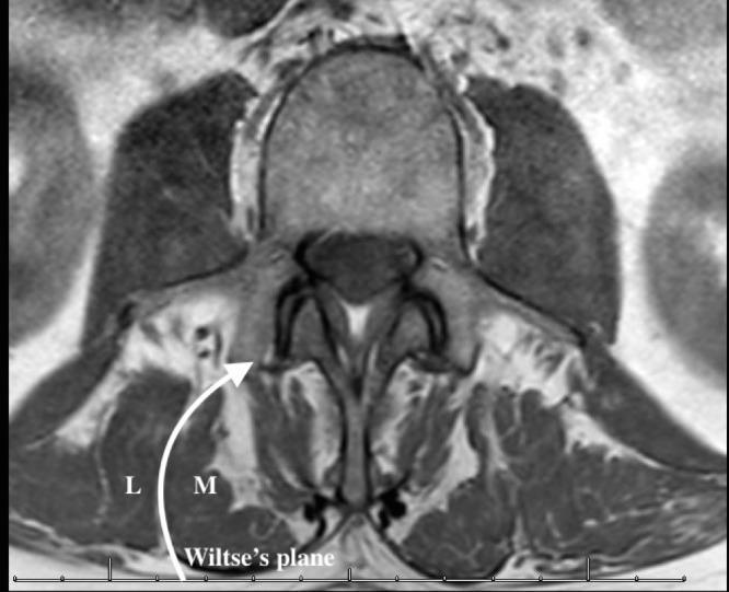
This diagnostic image is an axial slice from a Magnetic Resonance Imaging (MRI) scan of the lumbar spine, focusing on the posterior paraspinal musculature. The image demonstrates the anatomy relevant to the Wiltse (paraspinal) surgical approach. Key anatomical structures labeled include the multifidus muscle (M), which is positioned medially against the spinous process and lamina, and the longissimus muscle (L), part of the erector spinae group, situated more laterally. A prominent curved white arrow and line indicate Wiltse's plane, the natural avascular fascial cleavage interval between the multifidus and longissimus muscles. The MRI shows intermediate signal intensity for the muscle bellies and high signal intensity (bright) representing intermuscular fat and fascial layers, which clearly delineate the cleavage plane. Centrally, the vertebral body, spinal canal, and posterior elements are visible. This visual serves as an educational guide for spinal surgeons to identify the surgical trajectory for minimally invasive transforaminal lumbar interbody fusion (TLIF) or pedicle screw placement.
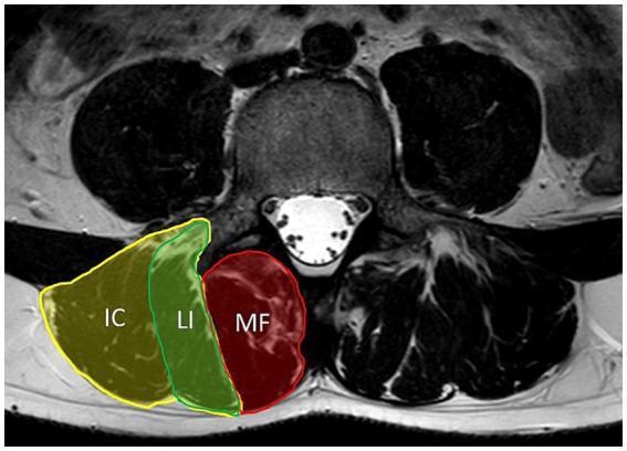
This diagnostic image is an axial T2-weighted MRI of the lumbar spine at the L4 level, illustrating the cross-sectional anatomy of the paraspinal musculature. The central vertebral body exhibits intermediate signal intensity, with the posterior spinal canal appearing hyperintense due to cerebrospinal fluid. On the left side of the image, the paraspinal muscles are highlighted and labeled to demonstrate their spatial relationships: the multifidus (MF) is positioned most medially, immediately adjacent to the spinous process and lamina. Lateral to the multifidus is the erector spinae group, subdivided into the longissimus (LI) muscle medially and the iliocostalis (IC) muscle most laterally. These muscles are characterized by intermediate to low signal intensity on the T2 sequence. This visual resource is essential for understanding core stabilization anatomy and evaluating clinical conditions such as axial myopathy, muscular atrophy, or fatty infiltration in patients with chronic low back pain or neuromuscular disorders like myotonic dystrophy.
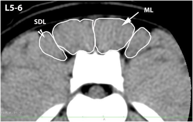
This diagnostic image is a transverse computerized tomography (CT) scan at the level of the L5-L6 vertebrae, focusing on the paraspinal musculature. The image demonstrates the cross-sectional anatomy of the lumbar spine and its associated soft tissue structures. Key anatomical regions are highlighted with white outlines to define the margins for clinical or research analysis. The Multifidus Lumborum (ML) is identified as the prominent muscle group located immediately lateral to the dorsal spinous processes. Positioned further lateral to the ML is the Sacrocaudalis Dorsalis Lateralis (SDL) muscle. Both muscle groups exhibit a relatively uniform soft-tissue density. The image illustrates the spatial relationship and precise borders of these muscles relative to the central vertebral body and dorsal bony landmarks. This type of imaging is typically used in musculoskeletal assessments to evaluate muscle cross-sectional area, symmetry, and potential atrophy or pathology in the lumbosacral region.
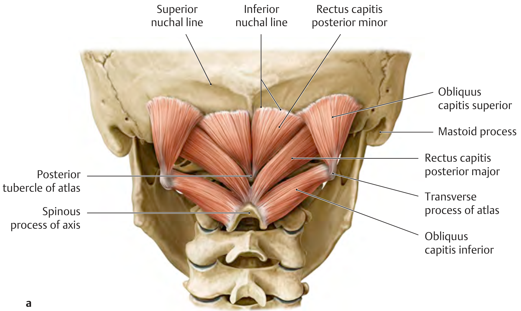
longus colli cervical prevertebral muscles anatomy
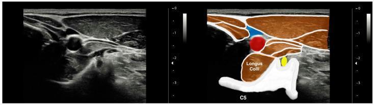
This diagnostic ultrasound image presents a cross-sectional view of the anterior neck anatomy at the level of the fifth cervical vertebra (C5), consisting of an original grayscale sonogram alongside a color-coded annotated duplicate. The image highlights the musculoskeletal and vascular relationships crucial for ultrasound-guided procedures. Centrally, the longus colli muscle is depicted as a hypoechoic, spindle-shaped structure positioned anterior to the hyperechoic vertebral body of C5. Superolateral to the longus colli, the common carotid artery (highlighted in red) appears as a non-compressible, circular, anechoic structure. The internal jugular vein (highlighted in blue) is visible superficial and lateral to the carotid artery, characterized by an oval, compressible anechoic lumen. The yellow annotation identifies the C5 nerve root residing within the transverse process groove. The image illustrates clear fascial planes separating the prevertebral muscles from the carotid sheath and superficial sternocleidomastoid muscle, serving as an educational reference for cervical regional anesthesia and soft tissue assessment.
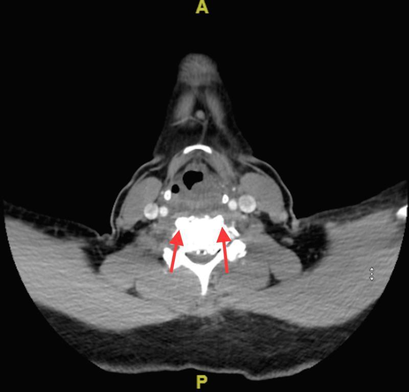
This axial computerized tomography (CT) scan of the cervical spine demonstrates a characteristic radiological finding of calcific tendonitis of the longus colli muscle. Centrally, a cervical vertebral body is visible with normal cortical density. Two red arrows point to amorphous, high-attenuation (hyperdense) calcifications located in the prevertebral soft tissue, specifically within the superior fibers of the longus colli muscle at the C1-C2 level. There is associated thickening of the prevertebral soft tissues, which can indicate edema or fluid accumulation. The surrounding anatomy includes the pharyngeal space and soft tissues of the neck. This diagnostic image is essential for differentiating this benign, self-limiting inflammatory condition from more serious pathologies like retropharyngeal abscess or spondylodiscitis. The content is suitable for medical education in radiology, emergency medicine, and orthopedics.
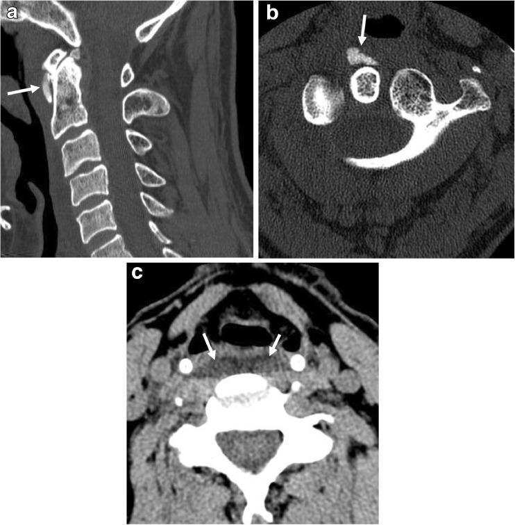
This composite diagnostic image features three non-contrast CT scans of the cervical spine in sagittal (a) and axial (b, c) planes, illustrating Acute Calcific Longus Colli Tendinitis (also known as prevertebral calcific tendinitis). Panel (a) and (b) highlight dense, amorphous calcifications (white arrows) located at the superior myotendinous junction of the longus colli muscle, specifically at the C1-C2 level anterior to the atlas and axis. Panel (c) is an axial soft-tissue window demonstrating significant prevertebral soft-tissue swelling and symmetric edema (white arrows) outlining the anterior margin of the bilateral longus colli muscles. This combination of pathognomonic amorphous calcification and prevertebral fluid/edema is typical of this inflammatory condition. The images are essential for distinguishing this self-limiting clinical entity from more serious conditions like retropharyngeal abscess. The content is suitable for radiology education, focusing on emergency medicine and musculoskeletal diagnostic imaging.
deep cervical muscles prevertebral neck anatomy diagram
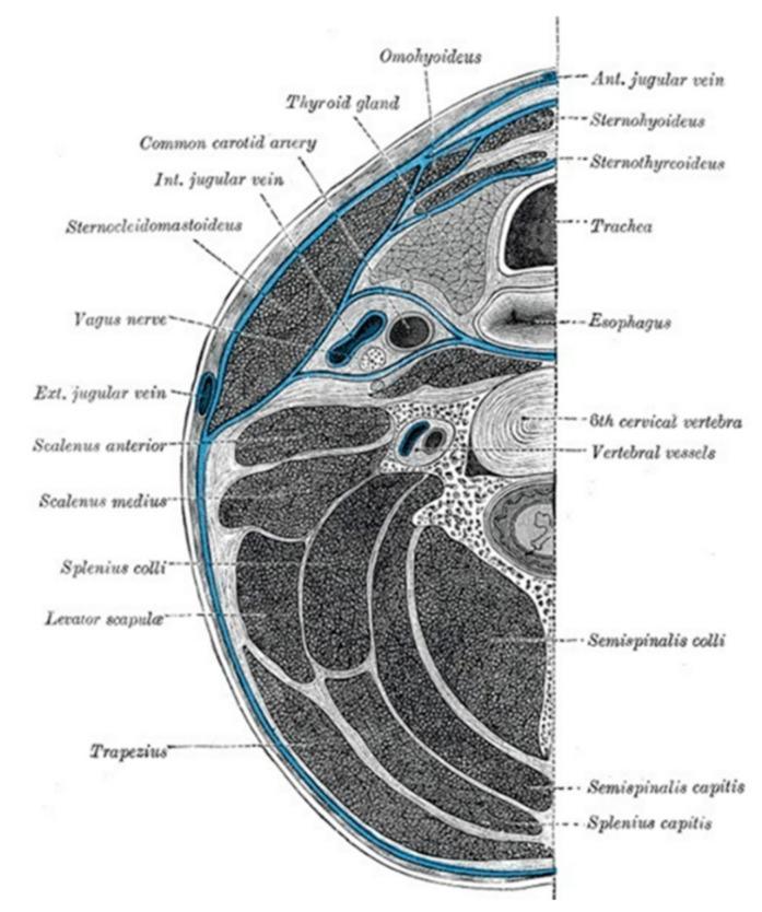
This medical illustration presents a transverse anatomical diagram of the neck at the level of the sixth cervical vertebra (C6), focusing on the compartmentalization provided by the deep cervical fascia (highlighted in blue). The diagram labels several critical structures within these fascial planes. The visceral compartment contains the trachea, esophagus, and thyroid gland. Lateral to the viscera, the carotid sheath is shown enveloping the common carotid artery, internal jugular vein, and vagus nerve. Muscular structures are identified including the sternocleidomastoid and trapezius (investing layer), the strap muscles (omohyoid, sternohyoid, sternothyroid), and the prevertebral/paravertebral muscles (scalenus anterior and medius, longus colli, semispinalis, and splenius groups). Vascular landmarks like the external and anterior jugular veins and vertebral vessels are also depicted. This diagram is designed for educational purposes to demonstrate the spatial relationships of cervical anatomy and the potential pathways for the spread of deep neck space infections.
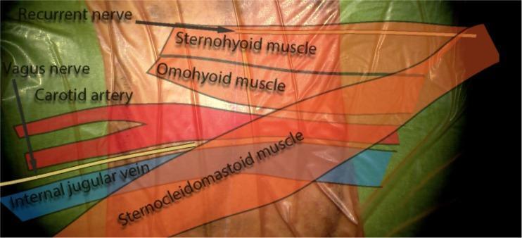
This surgical anatomy diagram illustrates the anatomical layers and key structures of the anterior neck. The image features a translucent overlay on what appears to be a clinical specimen or high-fidelity model to highlight vascular, neural, and muscular relationships relevant to anterior cervical spine surgery. Labeled muscular structures include the superficial sternocleidomastoid muscle (SCM) and the deeper strap muscles: the sternohyoid and omohyoid muscles. Medial to the SCM, the carotid sheath contents are depicted, including the carotid artery (red), internal jugular vein (blue), and the vagus nerve. Furthermore, the recurrent laryngeal nerve is shown in its characteristic course. This educational visual emphasizes the spatial orientation of superficial, middle, and deep cervical fascia layers, specifically demonstrating how the strap muscles and major vessels are positioned relative to the midline and the surgical corridor used for procedures such as anterior cervical discectomy and fusion (ACDF).
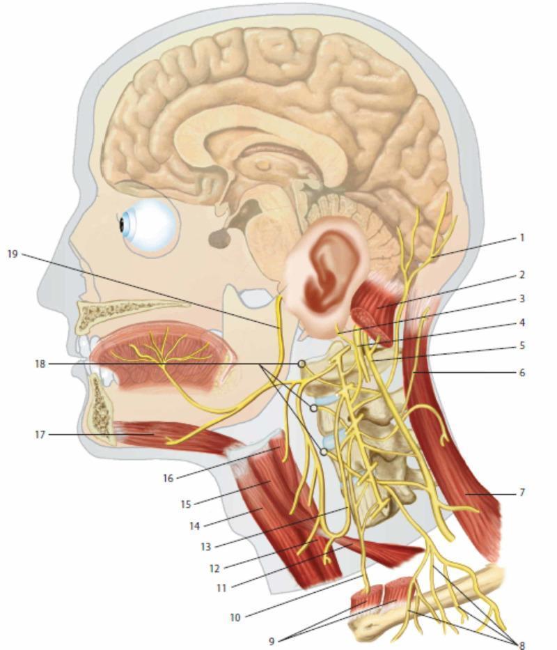
This medical anatomical diagram provides a lateral view of the human head and neck, focusing on the cervical plexus and its integration with cranial nerves. Key neural structures include the lesser occipital nerve (1), greater auricular nerve (3), and transverse cutaneous nerve of the neck (6), demonstrating the sensory distribution of the cervical plexus. The phrenic nerve (10) is shown descending inferiorly anterior to the prevertebral muscles (18). Cranial nerves X (vagus, 4), XI (accessory, 5), and XII (hypoglossal, 19) are illustrated to show their spatial relationships with cervical spinal branches. Muscular landmarks include the sternocleidomastoid (2, 9), trapezius (7), and infrahyoid muscles such as the omohyoid (11, 15) and thyrohyoid (16). The ansa cervicalis (13) is depicted innervating the sub-hyoid musculature. The diagram also illustrates the sagittal section of the brain and oral cavity, highlighting the innervation of the tongue and the relationship between the cervical spine vertebrae and emerging nerve roots. This resource is intended for medical education regarding the peripheral nervous system and regional anatomy of the neck.
Muscle Anatomy: Transversus Abdominis, Multifidus, and Deep Cervical Muscles
1. TRANSVERSUS ABDOMINIS
Origin
| Region | Structure |
|---|---|
| Superior | Inner surfaces of the 7th-12th costal cartilages |
| Posterior | Deep layer of the thoracolumbar fascia |
| Inferior | Inner lip of the iliac crest and anterior superior iliac spine (ASIS) |
| Inferolateral | Lateral part of the inguinal ligament |
Insertion
- Posterior layer of the rectus sheath and linea alba (via its aponeurosis)
- Pubic crest
Nerve Supply
- Intercostal nerves T5-T11
- Subcostal nerve (T12)
- Iliohypogastric nerve (L1)
- Ilioinguinal nerve (L1)
- Genitofemoral nerve (genital branch, for cremaster component)
Action / Function
| Contraction | Action |
|---|---|
| Bilateral | Active in forced expiration - compresses the abdomen; increases intra-abdominal pressure (Valsalva, defecation, parturition, vomiting) |
| Bilateral | Core stability - acts as a "corset" around the lumbar spine (key in core stabilization) |
| Unilateral | Rotates the trunk to the same side |
Functional significance: Along with the pelvic floor and diaphragm, transversus abdominis is a primary component of the deep "core" stabilization system. It is the first muscle to activate during limb movement, providing anticipatory postural control.
Diagram
2. MULTIFIDUS
Origin
| Level | Origin |
|---|---|
| Sacral | Sacrum (dorsal surface) and posterior superior iliac spine |
| Lumbar | Mammillary processes of L1-L5 |
| Thoracic | Transverse processes of T1-T12 |
| Cervical | Articular processes of C4-C7 |
Insertion
- Passes superomedially, spanning 2-4 vertebral levels
- Inserts into the base of spinous processes of vertebrae from L5 up to C2 (axis)
Nerve Supply
- Posterior (dorsal) rami of spinal nerves - at each segmental level (from C3 down to S4)
- Each fascicle is innervated by the medial branch of the dorsal ramus at its level of origin
Action / Function
| Contraction | Action |
|---|---|
| Bilateral | Extends the vertebral column (spine extension) |
| Unilateral | Lateral flexion to the same side AND rotation to the opposite side |
| Postural | Provides intersegmental stabilization - controls fine segmental movement; protects facet joints and intervertebral discs |
Functional significance: Multifidus is the largest contributor to lumbar spinal stiffness and segmental stability. It undergoes rapid atrophy after acute low back injury and is a primary rehabilitation target in lumbar pain syndromes.
Diagram
3. DEEP CERVICAL (PREVERTEBRAL) MUSCLES
3a. LONGUS COLLI (Longus Cervicis)
Origin
| Part | Origin |
|---|---|
| Vertical (medial) part | Anterior surfaces of C5-C7 and T1-T3 vertebral bodies |
| Superior oblique part | Anterior tubercles of transverse processes of C3-C5 |
| Inferior oblique part | Anterior surfaces of T1-T3 vertebral bodies |
Insertion
| Part | Insertion |
|---|---|
| Vertical part | Anterior surfaces of C2-C4 vertebral bodies |
| Superior oblique part | Anterior tubercle of the atlas (C1) |
| Inferior oblique part | Anterior tubercles of transverse processes of C5-C6 |
Nerve Supply
- Anterior rami of C2-C6 (direct muscular branches)
Action / Function
| Contraction | Action |
|---|---|
| Bilateral | Flexion of the cervical spine |
| Unilateral | Lateral flexion AND rotation of the cervical spine to the same side |
Clinical note: Longus colli is the surgical landmark in anterior cervical spine approaches (ACDF). It is elevated subperiosteally to expose the vertebral bodies. Injury to it can damage the nearby sympathetic chain (Horner syndrome). Calcific tendonitis of longus colli is a recognized cause of acute neck pain with prevertebral swelling.
3b. LONGUS CAPITIS
Origin
- Anterior tubercles of transverse processes of C3-C6
Insertion
- Basilar part of the occipital bone
Nerve Supply
- Direct branches from the cervical plexus (C1-C3)
Action / Function
| Contraction | Action |
|---|---|
| Bilateral | Flexes the head (atlanto-occipital joint) |
| Unilateral | Tilts and slightly rotates the head to the same side |
3c. RECTUS CAPITIS ANTERIOR
Origin
- Lateral mass of the atlas (C1)
Insertion
- Basilar part of the occipital bone
Nerve Supply
- Anterior ramus of C1
Action / Function
| Contraction | Action |
|---|---|
| Bilateral | Flexion at the atlanto-occipital joint |
| Unilateral | Lateral flexion at the atlanto-occipital joint |
3d. RECTUS CAPITIS LATERALIS
Origin
- Transverse process of the atlas (C1)
Insertion
- Basilar part of the occipital bone (lateral to the occipital condyles)
Nerve Supply
- Anterior ramus of C1
Action / Function
| Contraction | Action |
|---|---|
| Bilateral | Flexion at the atlanto-occipital joint |
| Unilateral | Lateral flexion at the atlanto-occipital joint |
Summary Table - Deep Cervical Prevertebral Muscles
| Muscle | Origin | Insertion | Nerve | Bilateral Action | Unilateral Action |
|---|---|---|---|---|---|
| Longus colli | C5-T3 bodies + TP of C3-C5 (3 parts) | C2-C4 bodies + atlas + C5-C6 TP | Ant. rami C2-C6 | Cervical flexion | Ipsilateral lateral flexion + rotation |
| Longus capitis | TP of C3-C6 | Basilar occipital bone | Cervical plexus C1-C3 | Head flexion | Ipsilateral tilt + rotation |
| Rectus capitis anterior | Lateral mass of atlas | Basilar occipital bone | Ant. ramus C1 | AO joint flexion | AO joint lateral flexion |
| Rectus capitis lateralis | TP of atlas | Basilar occipital bone (lateral) | Ant. ramus C1 | AO joint flexion | AO joint lateral flexion |
Diagram - Prevertebral Cervical Muscles
Quick Clinical Summary
| Muscle | Key Function | Nerve | Clinical Relevance |
|---|---|---|---|
| Transversus abdominis | Abdominal compression, core stability, expiration | T5-T12, L1 (iliohypogastric, ilioinguinal) | Core rehab, hernia, TAP block target |
| Multifidus | Intersegmental spinal stability + extension | Posterior (dorsal) rami - segmental | Low back pain, rapid atrophy after injury, lumbar rehab |
| Longus colli | Cervical flexion + ipsilateral rotation | Ant. rami C2-C6 | ACDF landmark, Horner risk, calcific tendonitis |
| Longus capitis | Head flexion | Cervical plexus C1-C3 | Anterior cervical stability |
| Rectus capitis ant. | AO flexion | C1 | Craniovertebral joint control |
| Rectus capitis lat. | AO lateral flexion | C1 | Craniovertebral joint control |
Write how to activate transverse abdominas and multifidus
"transversus abdominis" AND "multifidus" AND activation
transversus abdominis activation exercise drawing in abdominal hollowing
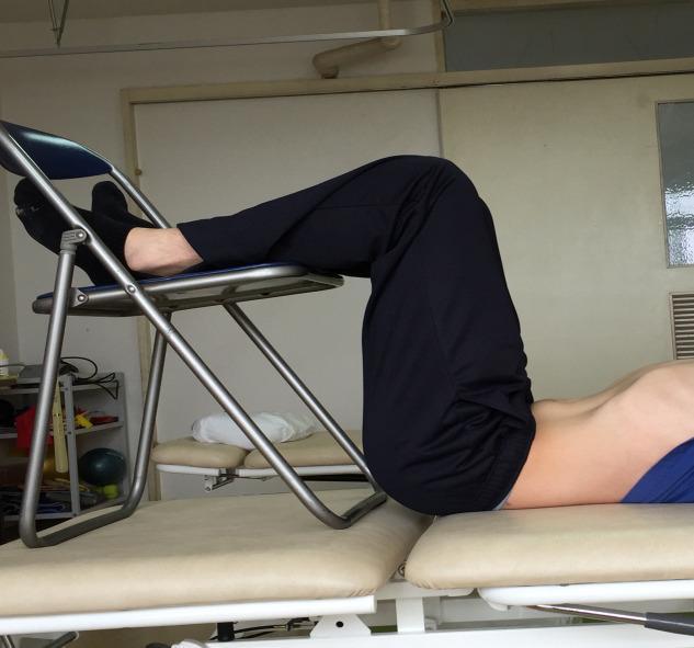
This clinical photograph demonstrates a participant performing an abdominal hollowing exercise, a therapeutic technique used in physical therapy and sports medicine to activate deep core stabilizers like the transversus abdominis. The subject is positioned supine on a padded examination table in a '90-90' posture. This involves 90 degrees of hip flexion and 90 degrees of knee flexion, with the lower legs and feet supported on the seat of a folding chair to neutralize the lumbar spine. The image captures the visible depression or 'hollowing' of the lower abdominal wall toward the spine, contrasting with the relatively stable position of the upper torso and limbs. This visual demonstrates the clinical application of core muscle recruitment protocols often used in rehabilitative research for low back pain management. The setting appears to be a clinical or research laboratory environment, emphasizing controlled positioning for consistent muscle activation measurements.
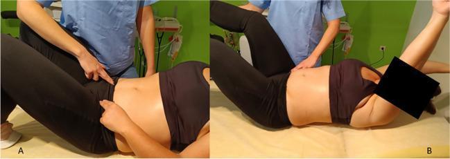
Two-panel clinical photograph demonstrating the activation and progression of the transversus abdominis (TrA) muscle during physical therapy. Panel A shows a patient in the supine hook-lying position (knees flexed, feet flat). A physiotherapist in blue scrubs is performing manual palpation of the lower abdominal wall, specifically just medial to the anterior superior iliac spine (ASIS), to assess the abdominal drawing-in maneuver (ADIM). The patient is also shown self-palpating on the contralateral side to monitor muscle tension. Panel B illustrates a progression of this stabilization exercise, where the patient maintains TrA contraction while introducing distal extremity movements. The patient is shown with the left leg extended and elevated and the right arm flexed overhead (crossed pattern). The physiotherapist maintains manual contact near the pelvic girdle to provide proprioceptive feedback and monitor trunk stability. This procedure is commonly used in postpartum rehabilitation for diastasis recti abdominis (DRA) and core stability training to ensure deep muscle engagement without excessive intra-abdominal pressure.

This composite educational clinical photograph illustrates a three-stage progression (A, B, and C) of motor control exercises (MCE) for lumbar stabilization, commonly used in the rehabilitation of chronic low back pain. Section A demonstrates 'Isolated Training,' featuring the abdominal drawing-in maneuver for transversus abdominis activation in supine and seated positions, and lumbar multifidus activation in sitting. Section B illustrates 'Light Dynamic Functional Tasks,' including heel slides in a crook-lying posture and spinal control exercises on an unstable seated base of support. Section C details 'Heavy Dynamic Functional Tasks' involving increased gravitational load and instability; exercises include supine bridging, bridging with an exercise ball (unstable base), quadruped (four-point kneeling) single-leg extensions, 'bird-dog' alternate arm/leg extensions, and advanced single-leg bridging on an exercise ball. Arrows indicate the intended direction of muscle contraction and spinal alignment. The progression emphasizes moving from static, local muscle activation to dynamic, global muscle integration with varying bases of support and limb involvement.
How to Activate Transversus Abdominis (TrA) and Multifidus
PHASE 1 — ISOLATED ACTIVATION
🔹 Transversus Abdominis: Abdominal Drawing-In Maneuver (ADIM)
-
Starting position: Lie on your back (supine), knees bent to 90°, feet flat on the floor (hook-lying position). Keep the spine in a neutral position - do not flatten or arch the lower back.
-
Find the target area: Place two fingers just medial and inferior to the ASIS (anterior superior iliac spine) on both sides. This is where TrA tension can be palpated.
-
The maneuver: Gently draw the lower abdomen inward and upward toward the spine - like "pulling your belly button away from your waistband." The movement should be:
- Slow and gentle (not a forceful suck)
- Lower abdomen only (not the upper abs)
- No rib cage movement
- No breath-holding - breathe normally throughout
- No posterior pelvic tilt - the spine must not move
-
What you should feel: A gentle, firm tension under your fingertips bilaterally. Not a bulge outward, but a tensioning inward.
-
Hold: 10 seconds per contraction, breathing normally throughout.
-
Reps: 10 repetitions × 3 sets.
Common error: People brace their entire abdomen (global bracing) or hold their breath - this recruits the obliques instead of TrA. The contraction should be subtle (~30% of maximum effort).
| Position | Use |
|---|---|
| Supine hook-lying | Best for beginners - gravity-assisted |
| Sitting upright | Next progression - functional position |
| 4-point kneeling (quadruped) | Good for feeling the lower abdomen drop and then draw up |
| Standing | Advanced - most functional |
🔹 Multifidus: Isolated Segmental Contraction
-
Starting position: Sit upright on a stool or firm chair, spine in neutral. Feet flat on the floor.
-
Find the target: Place your fingertips on the paraspinal muscles bilaterally, approximately 2-3 cm lateral to the spinous processes in the lumbar region.
-
The maneuver: Imagine "gently swelling" or "pushing out" the back muscles against your fingers without:
- Moving the spine
- Extending or rotating the trunk
- Tightening the buttocks
- Holding your breath
-
What you should feel: A gentle, diffuse swelling/hardening of the muscle under your fingers - symmetrically on both sides. It is a subtle "pushing out" sensation at the lumbar level.
-
Hold: 10 seconds, breathe normally.
-
Reps: 10 repetitions × 3 sets.
Key point: This is a tonic, low-level contraction (~30% MVC), not a powerful contraction. Multifidus functions primarily as a postural tonic muscle - it must be trained for endurance, not strength.
- Lie prone with a pillow under the abdomen
- Gently swell the lumbar multifidus against your (or a therapist's) fingers
- This eliminates gravity and is easier for very painful patients
PHASE 2 — CO-CONTRACTION + LIGHT DYNAMIC TASKS
TrA + Multifidus Co-Contraction Technique:
- Activate TrA first (ADIM)
- While maintaining TrA tension, gently swell multifidus
- Hold both contractions simultaneously while breathing normally
- Maintain this "inner brace" during movement
Exercises in Phase 2:
- Supine hook-lying position
- Co-contract TrA + multifidus first
- Slowly slide one heel along the floor to straighten the leg, then return
- Keep the spine completely still
- Alternate sides × 10 reps each
- Supine hook-lying
- Activate inner unit first
- Let one knee slowly fall outward toward the floor (hip external rotation) then return
- Spine must not rotate or tilt
- 10 reps each side
- Sit on a wobble board or foam pad
- Maintain TrA + multifidus co-contraction
- Balance without leaning - 30-60 second holds
PHASE 3 — HEAVY DYNAMIC / FUNCTIONAL TASKS
Exercises (in order of progression):
| Exercise | Position | Key Points |
|---|---|---|
| Supine Bridging | Supine, knees bent | Activate inner unit → lift pelvis → hold 10 sec |
| Quadruped / 4-point kneeling | Hands & knees | Activate TrA first, then extend alternate arm/leg ("Bird-Dog") |
| Bird-Dog | Quadruped | Opposite arm + leg extension while maintaining neutral spine - best combined TrA+multifidus exercise |
| Bridging on unstable surface | Supine on exercise ball | Adds challenge to spinal stability |
| Single-leg bridging | Supine | Advanced - increases asymmetric load on multifidus |
| Plank | Prone on elbows | Full inner unit engagement - 20-30 sec holds |
| Side plank | Lateral on elbow | Targets multifidus asymmetrically |
Key Principles Summary
| Principle | Transversus Abdominis | Multifidus |
|---|---|---|
| Contraction type | Gentle inward draw ("hollow") | Gentle outward swell ("push out") |
| Effort level | ~30% of max - tonic, not powerful | ~30% of max - tonic, postural |
| Spine position | Neutral - must NOT move during activation | Neutral - must NOT move |
| Breathing | Breathe normally throughout | Breathe normally throughout |
| Hold time | 10 seconds to start | 10 seconds to start |
| Starting position | Supine → sitting → standing | Sitting/prone → quadruped → standing |
| Key error | Breath-holding, global bracing, posterior pelvic tilt | Spinal extension, buttock tightening |
| Goal | Sustained tonic "corset" tension | Sustained segmental lumbar stiffness |
Important: Both muscles undergo rapid selective atrophy after even a single episode of acute low back pain. They do not self-rehabilitate even after pain resolves - a specific activation and retraining program is required. Current evidence (PMID 35879124) supports motor control training for restoring trunk muscle morphometry, reducing pain, and improving disability in chronic low back pain.