Essay on ncs
Asking for Preferences
Asking for Preferences
Reading File
Searching PubMed
nerve conduction studies electrodiagnosis
Finding Sources
Finding Sources
Reading File
Reading File
Reading File
Reading File
Reading File
Reading File
Reading File
I now have rich content from multiple authoritative textbooks. Let me write the comprehensive postgraduate-level essay.
Nerve Conduction Studies: Principles, Methodology, Interpretation, and Clinical Applications
Introduction
Nerve conduction studies (NCS) represent one of the most powerful diagnostic tools in clinical neurology and electrodiagnosis. First described systematically by Hodes and colleagues in 1948 using essentially the same transcutaneous stimulation techniques still employed today, NCS provides objective, quantitative, and reproducible assessment of the peripheral nervous system (PNS). Together with needle electromyography (EMG), NCS forms the backbone of the electrodiagnostic (EDX) examination - a discipline variously termed clinical EMG, electromyoneurography (ENMG), or simply electrodiagnosis - that localises and characterises disorders of nerve roots, peripheral nerves, neuromuscular junctions, and muscles.
The clinical EMG examination, of which NCS is the cornerstone, helps localise a neuromuscular problem at the motor or sensory neuron cell body, nerve root, peripheral nerve, neuromuscular junction, muscle membrane, or the muscle itself. It establishes the underlying pathophysiological process in these disorders and guides their management and prognosis (Bradley and Daroff's Neurology in Clinical Practice).
Physiological Basis
The fundamental principle underlying NCS is the application of an electrical stimulus to a peripheral nerve, which initiates propagating action potentials along motor, sensory, or mixed nerve fibers. These potentials are then recorded at a defined point along the nerve or at the target muscle.
NCS can assess only medium- to large-diameter myelinated nerve fibers - motor axons and sensory fibers conveying vibration and joint position sense. Small unmyelinated C fibers and lightly myelinated Aδ fibers responsible for pain and temperature sensation are not accessible by conventional NCS (Goldman-Cecil Medicine, 2 Volume Set). This is a key limitation that clinicians must bear in mind when evaluating patients with pain syndromes, small-fiber neuropathy, or autonomic dysfunction.
Three main NCS types are performed:
- Motor NCS: The nerve is stimulated while recording from a target muscle; the resulting potential is the compound muscle action potential (CMAP), also called the M wave.
- Sensory NCS: A sensory or mixed nerve is stimulated and the resulting sensory nerve action potential (SNAP) is recorded from another point along the same nerve, either orthodromically (in the physiological direction) or antidromically (opposite direction). Antidromic sensory studies offer technical advantages and are more widely used in routine practice.
- Mixed NCS: Both sensory and motor fibers are stimulated and recorded from a mixed nerve, yielding the mixed nerve action potential (MNAP).
Equipment and Technical Procedure
Stimulators
Two types of surface stimulators are used in NCS. Constant voltage stimulators regulate voltage output with current varying inversely with tissue impedance; constant current stimulators adjust voltage to maintain a set current regardless of skin resistance. In either case, the cathode (negative pole) depolarises the nerve while the anode hyperpolarises it - accidental reversal can produce anodal conduction block.
Supramaximal stimulation is a non-negotiable prerequisite for accurate NCS. The stimulating current is gradually increased until no further increase in the recorded potential is observed, then an additional 20-30% current is applied to ensure all available axons are recruited. Submaximal stimulation results in falsely low amplitudes and inaccurate velocities (Bradley and Daroff's Neurology in Clinical Practice).
Recording Electrodes
Surface (disk) electrodes are standard in clinical practice. For motor studies, the active electrode is placed over the endplate region (muscle belly) and the reference electrode over the muscle tendon. Ring electrodes are convenient for antidromic digital nerve recordings. Needle electrodes may be used to record from small, atrophic, or proximal muscles where surface recordings are unreliable.
For motor NCS, the nerve is stimulated at two or more points along its course; the difference in latencies divided by the inter-stimulus distance yields conduction velocity. For sensory NCS, digital averaging - which improves the signal-to-noise ratio proportionally to the square root of trial number - is often necessary to resolve the low-amplitude SNAP from background noise.
Parameters Measured and Their Significance
1. Conduction Velocity
Conduction velocity is calculated from the distance between proximal and distal stimulation sites divided by the difference in latencies. It reflects the propagation speed of the fastest-conducting, largest-diameter myelinated fibers.
- Normal motor conduction velocities: 50-70 m/s in the upper limbs, 40-60 m/s in the lower limbs.
- Velocities in normal subjects range from approximately 40-45 m/s (minimum) to 65-75 m/s (maximum) depending on the nerve studied (Adams and Victor's Principles of Neurology, 12th Edition).
- Slowing of conduction velocity is the hallmark of demyelinating pathology.
2. Distal Latency
Distal latency is the time from the stimulus artifact to the onset of the CMAP or SNAP at the most distal stimulation site. It incorporates conduction over the distal nerve segment plus neuromuscular junction transmission time (for motor studies). Prolonged distal latency suggests focal demyelination at the distal nerve segment - classically at the wrist in carpal tunnel syndrome (median nerve distal motor latency >4.5 ms in healthy adults).
3. Amplitude
- CMAP amplitude is measured in millivolts (mV) and reflects the summated electrical potential of all activated muscle fibers within the recording electrode's pickup region. It is a semiquantitative index of the number of functioning motor axons and the innervated muscle volume.
- SNAP amplitude is measured in microvolts (μV) and reflects the number of functioning large sensory axons.
- Reduction in amplitude is the primary electrodiagnostic signature of axonal loss (axonopathy), regardless of the etiology.
4. Waveform Duration and Morphology
Prolonged duration with polyphasic morphology occurs in demyelinating conditions due to temporal dispersion - the desynchronised arrival of action potentials from axons conducting at different velocities.
Late Responses: F Waves and H Reflexes
Beyond standard NCS, late responses extend the assessment to proximal nerve segments and nerve roots.
- F wave: A small, late motor response produced by antidromic activation of anterior horn cells, followed by orthodromic transmission back to the muscle. It assesses the entire motor axon from ventral horn to muscle, making it useful for detecting radiculopathies and proximal demyelination.
- H reflex: The electrical equivalent of the ankle jerk, predominantly assessing the S1 arc via the tibial nerve and soleus. Absent or asymmetric H reflex strongly suggests S1 radiculopathy or proximal neuropathy.
Physiological Variables and Sources of Error
Temperature
This is the most clinically important technical variable. Nerve impulse propagation slows by approximately 2.4 m/s (roughly 5%) per degree centigrade below 38°C. Cooling also increases CMAP and SNAP amplitude and prolongs response duration, mimicking axonal neuropathy at low temperature and potentially masking demyelination at high temperature. Limb skin temperature must be maintained at or above 33°C; if it falls below this threshold, warming with hot packs or water immersion is mandatory before recording. A correction factor of 5% of the calculated velocity per degree below 33°C may be applied, though this has been validated only in healthy subjects (Bradley and Daroff's Neurology in Clinical Practice).
Age
Myelination is incomplete at birth; newborn nerve conduction velocities are approximately half adult values and reach adult levels only by age 3-5 years. Conversely, velocities decline gradually after age 50, with approximately a 10% reduction by age 60. SNAP amplitudes also decline with ageing, and lower limb SNAPs may be absent in healthy individuals over 60 years - a finding that must not be misinterpreted as pathological in isolation.
Height and Nerve Length
An inverse relationship exists between height and conduction velocity, with lower limb nerves conducting 7-10 m/s slower than upper limb nerves. Contributing factors include abrupt distal axonal tapering, reduced axonal diameter distally, and shorter internodal distances. Adjustments to normal reference values are required for patients of extreme height.
Anatomical Anomalies
The Martin-Gruber anastomosis (median-to-ulnar crossover in the forearm) is present in approximately 15-30% of individuals and can profoundly distort NCS interpretation, producing unexpectedly high or low amplitudes and pseudo-conduction block. Awareness of such anatomical variants is essential to avoid misdiagnosis.
Electrodiagnostic Interpretation: Axonopathy vs. Demyelination
The distinction between axonal and demyelinating pathology is the central interpretive task in NCS.
| Feature | Axonopathy | Demyelinating Neuropathy |
|---|---|---|
| Amplitude (CMAP/SNAP) | Reduced | Near normal (unless severe) |
| Conduction velocity | Normal or mildly reduced | Markedly reduced (often <70% of lower limit of normal) |
| Distal latency | Normal or mildly prolonged | Markedly prolonged |
| F wave latency | Normal or mildly prolonged | Markedly prolonged |
| Temporal dispersion | Absent | Present |
| Conduction block | Absent | Present (in acquired demyelination) |
Conduction block - a reduction in CMAP amplitude (>50% is the standard threshold) when comparing proximal to distal stimulation - is pathognomonic of focal acquired demyelination and distinguishes conditions such as multifocal motor neuropathy and chronic inflammatory demyelinating polyneuropathy (CIDP) from hereditary demyelinating neuropathies such as Charcot-Marie-Tooth disease type 1, where conduction block is typically absent.
Sensory NCS findings are particularly informative for localisation. Because the sensory neuron cell body lies in the dorsal root ganglion (DRG), which is distal to the spinal cord, a lesion proximal to the DRG (e.g., nerve root avulsion, intraspinal lesion) leaves the SNAP intact despite clinical sensory loss. By contrast, a lesion distal to the DRG (e.g., plexopathy, peripheral neuropathy) produces SNAP abnormalities. This anatomical logic is the cornerstone of differentiating radiculopathy (normal SNAP) from plexopathy (abnormal SNAP).
Clinical Applications
1. Polyneuropathy
NCS documents the presence, modality (motor-predominant, sensory-predominant, or mixed), distribution (length-dependent vs. non-length-dependent), and pathophysiology (axonal vs. demyelinating) of polyneuropathy. This characterisation drives the differential diagnosis: a symmetric distal axonal sensorimotor polyneuropathy suggests diabetes mellitus, alcohol toxicity, or nutritional deficiency; a diffuse demyelinating polyneuropathy with slow velocities (<38 m/s) raises CIDP or hereditary neuropathy.
2. Entrapment Neuropathies
Focal prolongation of distal latency, slowed conduction velocity, and reduced amplitude across a specific anatomical site are the electrodiagnostic hallmarks of compression. Carpal tunnel syndrome (median nerve at wrist) is the most common; cubital tunnel syndrome (ulnar nerve at elbow), radial nerve entrapment, and fibular (peroneal) nerve entrapment at the fibular head are other frequent diagnoses. NCS can grade severity and guide surgical decisions.
3. Radiculopathy and Plexopathy
As discussed, the preserved SNAP in radiculopathy and the abnormal SNAP in plexopathy are the critical distinguishing features. NCS combined with needle EMG mapping of myotomal and dermatomal distribution allows precise root-level or plexus-level localisation.
4. Neuromuscular Junction Disorders
Repetitive nerve stimulation (RNS) at low frequency (3 Hz) produces a characteristic decrementing CMAP response in myasthenia gravis (MG) - a postsynaptic disorder, while a facilitating (incrementing) response at high-frequency stimulation (20-50 Hz) or after brief voluntary exercise is the signature of Lambert-Eaton myasthenic syndrome (LEMS), a presynaptic voltage-gated calcium channel disorder.
5. Motor Neuron Disease
In amyotrophic lateral sclerosis (ALS) and other motor neuron diseases, NCS reveals low CMAP amplitudes with preserved or near-normal conduction velocities and absent or unevokable SNAPs - consistent with pure motor axonopathy. The absence of conduction block helps exclude multifocal motor neuropathy, a treatable mimic.
6. Nerve Injury Assessment
Following traumatic nerve injury, NCS and EMG provide prognostic information about axonal continuity and regeneration potential, complementing imaging and guiding surgical timing. Serial studies can track recovery.
Limitations and Complementary Modalities
NCS has inherent limitations. It cannot assess small-fiber (C fiber and Aδ fiber) function; skin punch biopsy for intraepidermal nerve fiber density and quantitative sensory testing serve this role. NCS also provides no direct anatomical information about nerve morphology; high-resolution peripheral nerve ultrasound and MRI neurography are increasingly used to complement the electrophysiological assessment, particularly in focal neuropathies and inflammatory nerve disorders.
Reference values vary across laboratories and depend critically on age, sex, height, and limb temperature, demanding meticulous standardisation. Electrodiagnostic testing also requires considerable technical skill and clinical judgment; the study should be tailored to the clinical question and interpreted in the context of a detailed neurological examination (Bradley and Daroff's Neurology in Clinical Practice).
Conclusion
Nerve conduction studies remain indispensable in the diagnosis and management of peripheral nerve and neuromuscular diseases. By providing objective, quantitative, and reproducible data on conduction velocity, amplitude, distal latency, and late responses, NCS allows the clinician to localise lesions, characterise pathophysiology as axonal or demyelinating, assess severity, and monitor progression or treatment response. Mastery of the technical requirements - supramaximal stimulation, temperature control, age-appropriate reference values, and awareness of anatomical variants - is as important as interpretive expertise. Used in conjunction with needle EMG and, where appropriate, complementary imaging, NCS forms the foundation of modern peripheral nerve diagnosis.
Sources:
- Bradley and Daroff's Neurology in Clinical Practice (Chapter on Nerve Conduction Studies and EMG)
- Adams and Victor's Principles of Neurology, 12th Edition (Chapter 2: Electromyography and Nerve Conduction Studies)
- Goldman-Cecil Medicine, International Edition (Chapter 366: Neurologic Diagnostic Tests)
- Pfenninger and Fowler's Procedures for Primary Care, 3rd Edition (Chapter 224: NCS Interpretation)
- Recent literature: Tankisi H et al., Clin Neurophysiol 2024 [PMID: 38805900] (muscle excitability testing as a complementary modality)
Essay on tendon suturing techniques for postgraduate orthopaedics exam
Reading File
Finding Sources
Finding Sources
Searching PubMed
flexor tendon repair suture technique
Reading File
Finding Sources
Reading Article
Reading File
Finding Sources
Reading File
Reading File
Reading File
Finding Sources
Reading File
Reading File
Reading File
Reading File
Reading File
I now have comprehensive material from Campbell's (2026) and Miller's Review. Let me compose the full postgraduate essay.
Tendon Suturing Techniques
Introduction
The surgical repair of severed tendons is one of the most technically demanding challenges in orthopaedic and hand surgery. The goal of tendon suture is to approximate the divided ends accurately, hold that position during the biological healing phase, and withstand the mechanical stresses of early postoperative mobilisation - which is now universally accepted as essential for optimal functional recovery. The 2026 consensus of the International Federation of Societies for Surgery of the Hand (IFSSH) has crystallised current best practice: strong multi-strand core repairs, running peripheral (epitendinous) sutures, early true active flexion, and abandonment of traditional weaker two-strand configurations (Tang et al., J Hand Surg Eur Vol, 2026 [PMID: 41637469]).
Understanding tendon suturing techniques requires knowledge of tendon biology, biomechanical principles, suture material properties, and the anatomical zones that govern repair strategy - particularly for flexor tendons of the hand, where the consequences of failed or adhesion-complicated repairs are most functionally significant.
Tendon Biology and Healing
Tendons heal through two mechanisms:
- Intrinsic healing: Directed by tendon fibroblasts (tenocytes) within the tendon substance. This is the dominant mode and produces healing with minimal adhesion.
- Extrinsic healing: Mediated by fibroblasts invading from the surrounding tendon sheath and peritendinous tissue. It is a secondary contributor but is a major source of adhesion formation, which restricts gliding and impairs function.
Biomechanical stimuli profoundly influence tendon healing. Cyclic tension applied during controlled early mobilisation promotes intrinsic healing, reduces adhesion formation, and increases the strength of repair tissue. This biological rationale underpins the shift toward early active motion protocols, which in turn place stringent biomechanical demands on the repair itself (Miller's Review of Orthopaedics, 9th Edition).
The risk of tendon rupture is greatest at approximately three weeks after repair, and failure characteristically occurs at the suture knots rather than through the tendon substance. This temporal vulnerability corresponds to the phase of maximal collagen remodelling and before repair tissue achieves mature tensile strength.
Characteristics of an Ideal Tendon Repair
Strickland's criteria, endorsed in Campbell's Operative Orthopaedics (15th Edition, 2026), define the ideal repair as one that:
- Allows easy placement of sutures in the tendon
- Achieves secure suture knots
- Creates a smooth juncture of tendon ends
- Produces minimal gapping at the repair site
- Minimally interferes with tendon vascularity
- Provides sufficient strength throughout healing to permit early motion stress
These criteria highlight the tension between technical ease and biomechanical robustness - a tension that has driven the evolution from simple two-strand repairs toward multi-strand configurations.
Suture Material
The choice of suture material is fundamental to repair strength.
Monofilament stainless steel has the highest tensile strength but is difficult to handle, tends to pull through tendon tissue, and forms a bulky knot; it is largely reserved for the distal forearm where access allows.
Absorbable sutures - catgut, polyglycolic acid (Dexon, Vicryl) - lose tensile strength too early (within 2-3 weeks) to be relied upon for the core repair.
Synthetic non-absorbable sutures in clinical use include:
- Monofilament nylon (Ethilon): easier to handle than steel, but permits earlier gap formation at the repair site compared with braided materials.
- Polypropylene (Prolene): similar to nylon; loses strength faster than caprolactam-based sutures.
- Polydioxanone (PDS): a slowly absorbable monofilament comparable in strength to polypropylene over 28 days; useful when permanent suture is undesirable.
- Braided polyester (Ticron, Mersilene, FiberWire): the most widely used core suture in current practice. Braided polyester provides superior resistance to disrupting forces and gap formation, handles well, and has reliable knot characteristics.
- Braided polyethylene: biomechanically the strongest non-metallic suture, though less widely used due to cost.
Suture calibre has a major effect on repair strength: a 4-0 suture is estimated to be 66% stronger than a 5-0 suture, and a 3-0 suture 52% stronger than a 4-0 suture. A 3-0 suture in a two-strand or four-strand core configuration is recommended where an early active motion programme is planned. In clinical practice, 3-0 sutures are favoured for tendons in the forearm, palm, and larger digits; 4-0 handles better in smaller digits. The epitendinous (peripheral) suture is typically placed with 5-0 or 6-0 monofilament nylon (Campbell's Operative Orthopaedics, 15th Ed, 2026).
The Core Suture: Principles and Strand Count
The core suture is the structural backbone of the repair. Its most important biomechanical property is the number of suture strands crossing the repair site.
Repair strength is directly proportional to strand count. Six- to eight-strand configurations have superior strength and stiffness compared with two- or four-strand repairs. This has led to a clear evolution in clinical practice:
- Two-strand repairs (e.g., simple modified Kessler alone) are no longer considered adequate for early active mobilisation.
- Four-strand repairs represent the minimum for early active motion protocols.
- Six- and eight-strand repairs are now preferred in zone II and in all zones where early active flexion is planned (IFSSH 2026 consensus; Miller's Review of Orthopaedics, 9th Edition).
Additional determinants of core suture strength:
- Purchase (the longitudinal distance from the cut tendon end to the transverse component of the core suture): should be 0.7-1.2 cm. Longer purchase increases holding strength.
- Locking vs. grasping configuration: Locking-loop sutures trap bundles of tendon fibers and resist gap formation more effectively than simple grasping configurations.
- Knot position: Knots placed between the tendon stumps are foreign bodies that impede gliding and should be avoided; the 2026 IFSSH guidelines explicitly recommend against inter-stump knot placement.
- Dorsal vs. volar placement: Dorsally placed core sutures provide approximately 58% greater strength. However, traditional teaching placed sutures in the volar third to avoid compromising intratendinous blood supply. Current practice recognises that with multi-strand repairs, some dorsal placement is acceptable.
Core Suture Configurations
1. Bunnell Stitch
The classic Bunnell stitch is a crisscross intratendinous suture. While historically important, it significantly compromises intratendinous vascularity by its zigzag passage through the tendon substance. The Kleinert modification of the Bunnell (using the suture more at the surface) was an improvement. The original Bunnell configuration is now largely abandoned for primary repair due to its vascularity compromise and difficulty of placement in confined spaces.
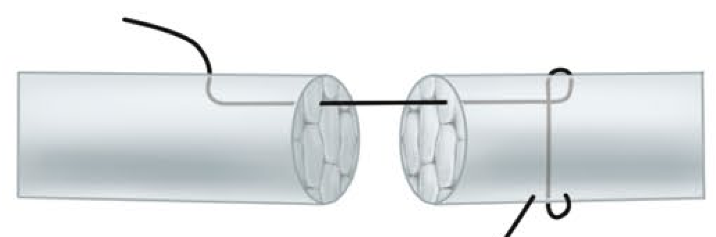
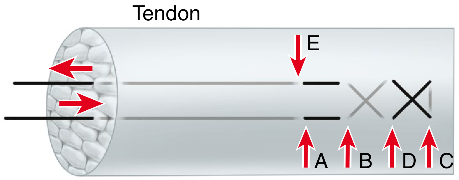
2. Kessler Stitch
The Kessler grasping stitch uses a suture that passes transversely across the cut end and then longitudinally through the substance of each tendon stump, creating a "locking" purchase at each side. It was a major advance over the Bunnell stitch in terms of vascularity preservation. The modified Kessler (Tajima modification, placing the knot within the repair site) became the standard two-strand repair for decades.
A four-strand adaptation of the Kessler repair has been shown to be significantly stronger than the two-strand modified Kessler and is a straightforward modification for confined spaces within the flexor sheath.
3. Modified Kessler (Tajima) Stitch
Two modified Kessler sutures placed at right angles to each other yield a four-strand repair. This remains a widely used technique because it is versatile, technically accessible, and provides adequate strength when combined with a robust epitendinous suture.
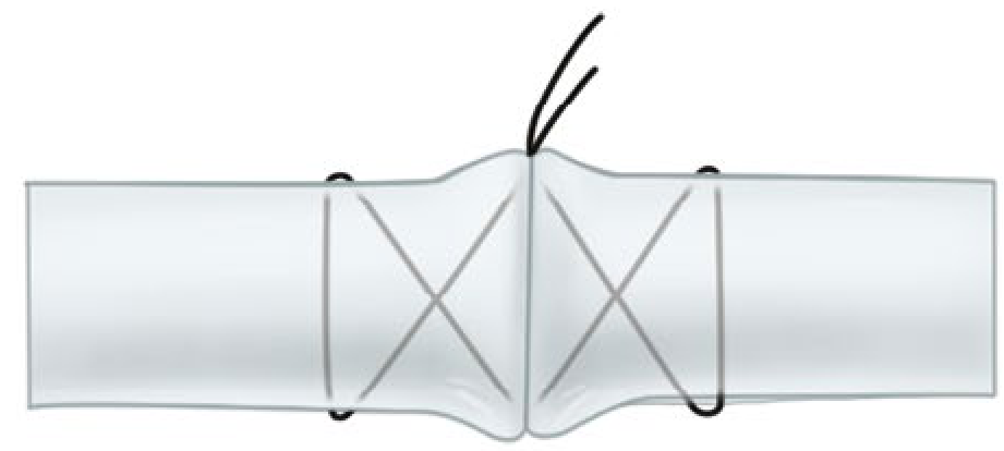
4. Tsuge (Loop) Stitch
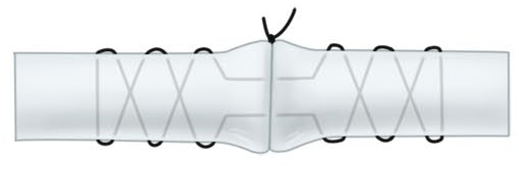
The Tsuge stitch uses a pre-formed suture loop placed through the tendon. The double-looped Tsuge modification creates a six-strand repair from a single suture, offering mechanical advantages with reduced bulk at the repair site.
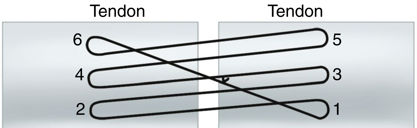
5. Savage Six-Strand Repair
The Savage repair employs six strands across the repair site using a specific crossing pattern through the tendon. The original description was technically demanding but biomechanically strong; cadaver studies confirmed its superior strength over two-strand repairs.
6. Lee Four-Strand Technique
The Lee technique uses two sutures to create four strands, with knots buried within the repair site. It offers a practical four-strand repair with acceptable bulk.
7. Indiana Four-Strand Repair with Running Lock Suture
Combines a four-strand core with an integrated running-lock peripheral suture in a single technique, simplifying the repair process and reducing operative time.
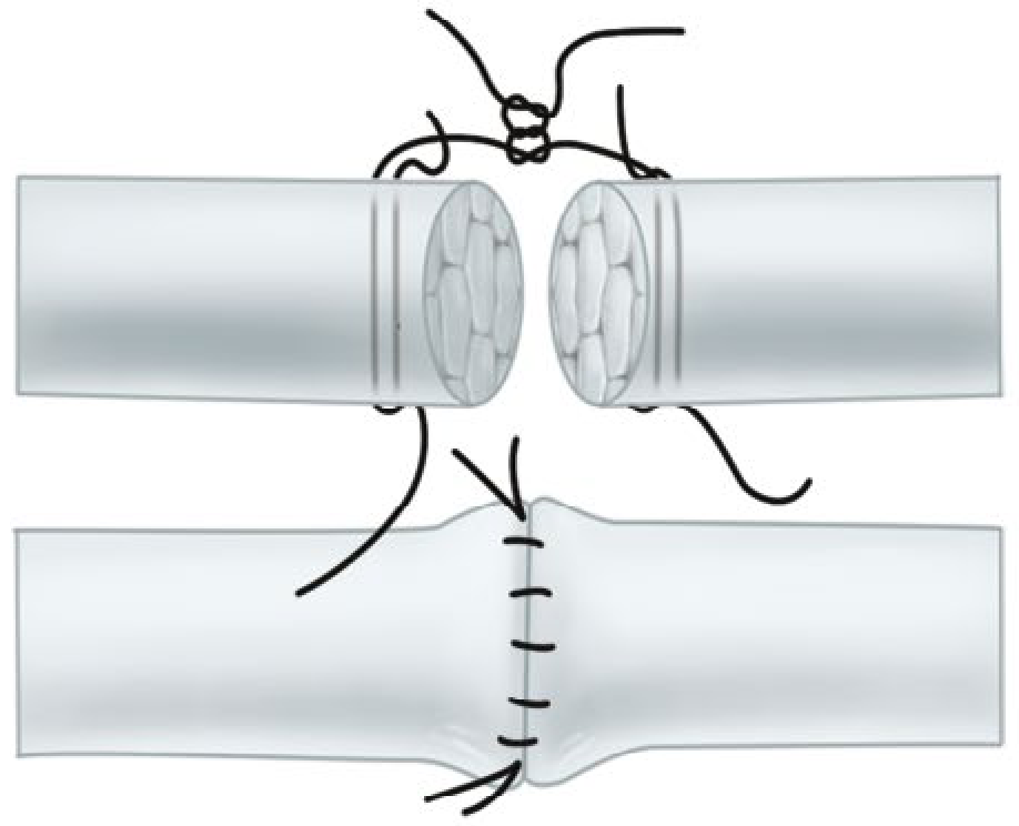
8. M-Tang Repair (Multiple-Looped Suture)
Described by Tang et al. and validated in large clinical series, the M-Tang repair uses multiple looped sutures arranged in a triangular cross-sectional configuration - one thread in the palmar half and one each in the two sides of the dorsal half of the tendon. It achieves a six-strand repair with knots arranged away from the inter-stump gap, consistent with current guidelines against inter-stump knot placement. It is specifically recommended in the 2023 Hand Clinics review as a modern standard (Tang et al., Hand Clin, 2023 [PMID: 37080646]).
9. Six-Strand Double-Loop Repair (Lim-Tsai)
Core sutures are placed to minimise tendon constriction, with the core held slightly overlapped before stitch placement. A cadaveric comparative study (Gill et al.) confirmed the biomechanical superiority of this repair over the modified Kessler and several other techniques.
10. Cruciate and Four-Strand Cruciate Repairs
The cruciate configuration distributes load across four strands and distributes stress more evenly across the repair site, reducing peak stress concentration at any single suture-tendon interface.
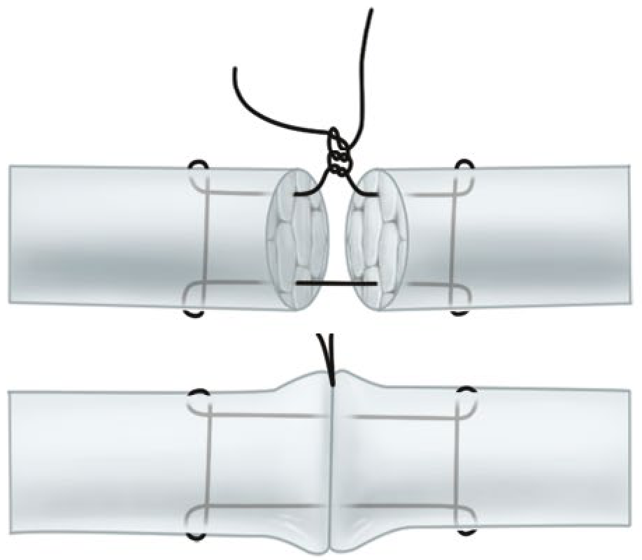
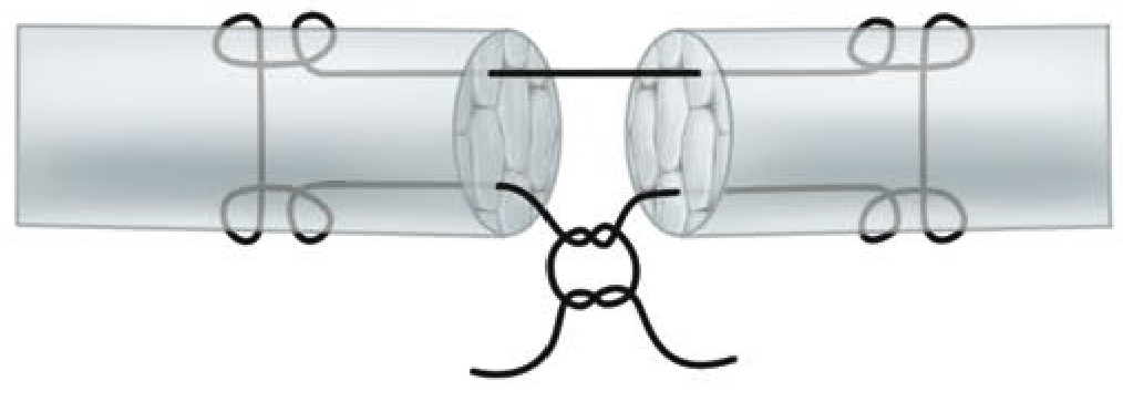
The Peripheral (Epitendinous) Suture
The peripheral or epitendinous suture is placed circumferentially around the repair site, typically as a continuous running stitch with 5-0 or 6-0 monofilament. Its contributions are:
- Reduces bulk at the repair site, minimising the risk of triggering at pulley level
- Smooths tendon contour, reducing resistance to gliding
- Enhances overall repair strength by 10-50% - a widely cited figure from biomechanical studies
- Supports approximately 50% of the load to failure in some configurations, making it not merely a cosmetic addition but a structural component
The epitenon-first technique - placing the peripheral suture before the core sutures - has been shown to be 22% stronger than the modified Kessler with a conventional epitendinous repair (Campbell's Operative Orthopaedics, 15th Ed, 2026). The interlocking horizontal mattress epitendinous stitch had the highest load to failure and greatest resistance to gap formation among tested circumferential techniques.
The 2026 IFSSH consensus specifies that traditional running peripheral sutures should be omitted when a six-strand repair is used, as the additional bulk may outweigh the benefit. This is an important recent departure from older teachings.
Flexor Tendon Zones and Repair Strategy
The Verdan zone classification divides the flexor tendon anatomy of the hand into five zones (and a separate thumb zone) that directly govern surgical strategy:
| Zone | Location | Significance |
|---|---|---|
| I | Distal to FDS insertion (FDP only) | FDP repair alone; pull-out suture to bone if needed |
| II | "No man's land" - within digital flexor sheath (A1 to FDS insertion) | Most demanding; both FDP and FDS repair; critical pulley preservation |
| III | Palm (A1 pulley to distal edge of carpal tunnel) | Both tendons; simpler environment |
| IV | Within carpal tunnel | Uncommon laceration; both tendons |
| V | Proximal to carpal tunnel | Muscular attachments; generally good prognosis |
Zone II ("no man's land," so called by Bunnell) is the most technically challenging and clinically significant zone. The flexor tendons traverse the narrow fibro-osseous sheath between the pulleys, and adhesion formation between the repair site and the sheath wall is the principal cause of failed outcomes. In zone II:
- Four-strand core sutures with locking components and buried knots are preferred as a minimum.
- The A2 and A4 pulleys must be preserved to prevent bowstringing (A2 is the most important).
- A portion of A2 may be incised (but not entirely excised) to facilitate tendon passage and reduce triggering at the repair site.
Extensor Tendon Repair
Extensor tendon injuries are classified by Verdan into eight zones over the dorsum of the hand and wrist, with different technical requirements by zone.
- Zone I-II (over DIP and PIP joints): These injuries (mallet finger, central slip avulsion) are frequently treated conservatively with splinting. When operative repair is needed, a modified Bunnell or Kleinert modification of the Bunnell suture is stronger than figure-of-eight or mattress sutures for core repair. A Silfverskiöld continuous suture reinforcement may be added.
- Zone III-IV (over PIP joint and proximal phalanx): Both the central slip and lateral bands require attention; boutonnière deformity results from untreated central slip injuries.
- Zone V-VIII (over MCP joint to forearm)**: The extensor environment is more forgiving given wider cross-sectional area and less confined anatomy. Modified Bunnell, modified Kessler, or augmented Becker configurations with a cross-stitch reinforcement provide strong repairs in zones IV-V. For zones VI-VIII, modified Kessler, modified Bunnell, modified Becker (MGH), and Krackow-Thomas techniques are all appropriate.
Suture Material for Core vs. Epitendinous Layers: Summary
| Layer | Preferred Material | Calibre |
|---|---|---|
| Core suture (large digit/forearm) | Braided polyester (FiberWire, Ticron) | 3-0 |
| Core suture (small digit) | Braided polyester | 4-0 |
| Core suture (looped, e.g. M-Tang) | Looped nylon (Supramid) | 4-0 or 5-0 |
| Epitendinous suture | Monofilament nylon | 5-0 or 6-0 |
Postoperative Rehabilitation
The biomechanical adequacy of the repair directly enables the rehabilitation protocol:
- A minimum four-strand repair with epitendinous suture is required for early active flexion protocols. Immobilisation-based protocols are no longer recommended for compliant adult patients (Miller's Review of Orthopaedics, 9th Ed; IFSSH 2026).
- The WALANT technique (Wide Awake Local Anaesthesia No Tourniquet, using lidocaine with epinephrine) allows intraoperative assessment of repair integrity with active patient participation, and is increasingly adopted as best practice.
- Place-and-hold exercises (passive flexion followed by active holding) are now recommended to be abandoned in favour of true early active flexion (IFSSH 2026).
- Young children who cannot comply with protected motion protocols require cast immobilisation for four weeks.
Complications
- Rupture: Risk is greatest at three weeks; failure occurs at the knots. Inadequate strand count, excessive tension during early mobilisation, and knot placed between stumps are the main technical causes.
- Adhesion formation: The principal obstacle to functional recovery, especially in zone II. Minimised by atraumatic handling, meticulous technique, smooth repair site, and early active mobilisation.
- Triggering: Caused by a bulky repair impinging on the flexor sheath at pulley level. Prevented by well-placed epitendinous suture and, if necessary, partial A2 excision.
- Bowstringing: Results from sacrifice of the A2 pulley; must be avoided.
Conclusion
The evolution of tendon suturing techniques has been driven by biomechanical research, clinical outcome data, and the rehabilitation imperative of early active mobilisation. The modified Kessler suture that dominated practice for decades has been superseded by multi-strand techniques - four strands as a minimum, six or eight strands preferred. The epitendinous suture is an integral structural component, not an afterthought. Suture material selection, strand count, purchase length, locking configuration, and knot position are all modifiable variables that determine repair quality. The 2026 IFSSH consensus formalises these advances and should guide current practice. Technical mastery of the core techniques - modified Kessler, M-Tang, Savage, Lee, and the double-looped Tsuge - combined with a thorough understanding of zonal anatomy and rehabilitation biology, represents the standard expected of a postgraduate orthopaedic surgeon.
Sources:
- Campbell's Operative Orthopaedics, 15th Edition, 2026 (Chapter 71: Basic Tendon Repair Techniques and Flexor Tendon Injuries)
- Miller's Review of Orthopaedics, 9th Edition (Chapter on Tendon Injuries and Overuse Syndromes)
- Tang JB, Lalonde D, Fernandes CH et al. "The IFSSH consensus and current guidelines on flexor tendon repairs and reconstruction." J Hand Surg Eur Vol, 2026 [PMID: 41637469]
- Tang JB, Pan ZJ, Munz G. "Flexor Tendon Repair Techniques: M-Tang Repair." Hand Clin 2023 [PMID: 37080646]
Provide images for all the suture configurations
Loading Image
Loading Image
Loading Image
Loading Image
Loading Image
Loading Image
Loading Image
Loading Image
Loading Image
Loading Image
Here are the textbook illustrations for all the major suture configurations, sourced directly from Campbell's Operative Orthopaedics (15th Ed, 2026):
Core Suture Configurations
1. Bunnell Stitch
2. Kessler Grasping Stitch (2-strand)
3. Modified Kessler (Tajima) Stitch - Single Knot
4. Tsuge (Loop) Stitch

5. Double Grasping (One Suture)
6. Crisscross Stitch
7. Mason-Allen (Chicago) Stitch
8. Savage Six-Strand Repair
9. Lee Four-Strand Technique
10. Core + Epitendinous Repair (combined view)
The image below shows the Mason-Allen core + epitendinous running circumferential suture combination - illustrating how the peripheral stitch smooths the repair site and adds 10-50% to total repair strength:
Summary Table
| Configuration | Strands | Knot position | Key advantage |
|---|---|---|---|
| Bunnell | 2 | Dorsal surface | Historical only |
| Kessler | 2 | Inter-stump | Simple grasping |
| Modified Kessler | 2 | Within tendon | Widely used; can be doubled to 4-strand |
| Tsuge loop | 2-4 | Away from gap | Low-bulk knot |
| Double grasping | 4 | Lateral surface | Better gap resistance |
| Crisscross | 4 | Dorsal surface | Strong; more vascularity compromise |
| Mason-Allen | 4 | External | Excellent for large tendons (rotator cuff) |
| Lee | 4 | Buried within | Two knots; technically reproducible |
| Savage | 6 | Crossed within | Highest strength; technically demanding |
| M-Tang (looped) | 6 | Triangular, away from gap | Current standard; IFSSH 2026 endorsed |
All images are from Campbell's Operative Orthopaedics, 15th Edition, 2026, Figure 71.9 (tendon suture techniques panel) and Figure 71.5/71.6/71.7.
Essay on trendelenburg gait for orthopaedic postgraduate exam
Finding Sources
Finding Sources
Searching PubMed
Trendelenburg gait hip abductor weakness
Reading File
Reading File
Reading File
Reading File
Finding Sources
Finding Sources
Reading File
Reading File
Reading File
Reading File
Finding Sources
Finding Sources
Reading File
Reading File
Finding Sources
Loading Image
Reading Article
I now have comprehensive material from Campbell's (2026), Adams & Victor's Neurology, Bailey & Love's Surgery, Gray's Anatomy, Firestein & Kelley's Rheumatology, Miller's Review, Harrison's Principles, and recent literature. Let me write the full essay.
Trendelenburg Gait
Introduction
The Trendelenburg gait is one of the most clinically informative and frequently encountered abnormal gait patterns in orthopaedic practice. Named after the German surgeon Friedrich Trendelenburg (1844-1924), who described the eponymous sign in 1895, it results from weakness or dysfunction of the hip abductor mechanism - principally the gluteus medius and gluteus minimus muscles - and manifests as a characteristic lateral lurching or waddling pattern during walking. Its recognition, correct interpretation, and accurate attribution to an underlying cause are fundamental competencies for the orthopaedic surgeon.
Normal Hip Biomechanics During Gait
To understand the Trendelenburg gait, a firm grasp of normal hip mechanics in the stance phase of walking is essential.
During normal gait, as weight is transferred to one lower limb (the stance limb), the hip abductor muscles of that side - primarily the gluteus medius, assisted by gluteus minimus and tensor fascia lata - contract forcefully to hold the pelvis level or to elevate the non-weight-bearing side slightly. This abductor contraction prevents the contralateral pelvis from dropping during single-limb support, which is the moment when the body's full weight is borne through one hip.
The abductors act as a force couple with the body weight through the hip joint centre. Because the abductors insert on the greater trochanter and their moment arm (lever arm) is considerably shorter than that of body weight acting through the femoral head, the abductors must generate a force approximately 1.5-3 times body weight to balance the pelvis. Kinetic analysis reveals that forces across the hip joint reach three times body weight during normal walking and up to ten times body weight during running and jumping (Bailey and Love's Short Practice of Surgery, 28th Ed).
This normal mechanism - abductor contraction holding the pelvis level during the stance phase - is tested clinically by the Trendelenburg test and, when impaired, produces the characteristic gait abnormality during walking.
Anatomy of the Hip Abductor Mechanism
The hip abductor complex consists of:
- Gluteus medius: The principal abductor. It arises from the outer surface of the ilium between the anterior and posterior gluteal lines and inserts on the superolateral surface of the greater trochanter. Its anterior fibres assist internal rotation; its posterior fibres assist external rotation.
- Gluteus minimus: Lies deep to gluteus medius, arising from the outer ilium between the anterior and inferior gluteal lines, inserting on the anterior aspect of the greater trochanter. It also assists internal rotation.
- Tensor fascia lata (TFL): Acts as a minor abductor through its insertion into the iliotibial band.
All three muscles are innervated by the superior gluteal nerve (L4, L5, S1), which exits through the greater sciatic foramen above the piriformis and travels anteriorly between gluteus medius and minimus. This nerve's anatomical course makes it uniquely vulnerable during surgical approaches to the hip - a fact of major clinical importance.
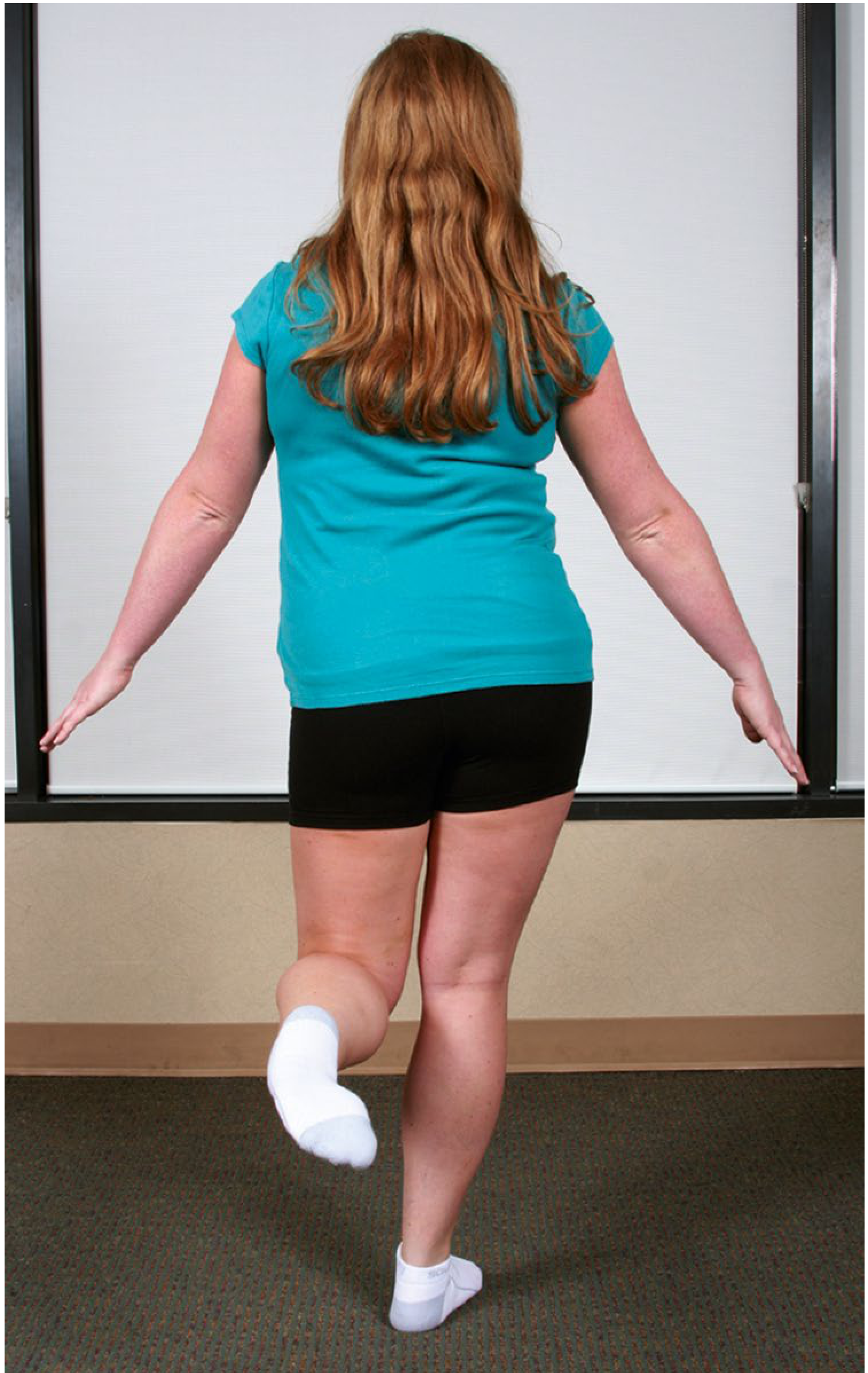
The Trendelenburg Sign: Clinical Testing
The Trendelenburg test assesses the ability of the hip abductor muscles to stabilise the pelvis on the femur during single-limb stance. It is performed as follows:
- The examiner stands behind the patient.
- The patient is asked to stand on one leg (the affected limb).
- Normally, the contralateral (unsupported) hemipelvis rises or remains level.
- A positive test is recorded when the unsupported hemipelvis drops, indicating failure of the stance-limb abductors to maintain pelvic level.
The test is positive for abductor weakness when the pelvis sags more than 2 cm during single-leg stance on the limb tested (Campbell's Operative Orthopaedics, 15th Ed, 2026).
The examiner may also apply gentle upward pressure on the anterior superior iliac spine of the stance limb side, and increased resistance indicates weakness (Bailey and Love's Short Practice of Surgery, 28th Ed).
Importantly, the Trendelenburg sign is nonspecific in that it may be positive in both primary neurological/muscular disorders and in structural hip diseases that secondarily weaken the abductors.
The Trendelenburg Gait: Mechanism and Appearance
During walking, the Trendelenburg gait manifests during the stance phase of the affected limb:
- As weight is borne on the affected side, the weakened abductors fail to prevent the contralateral hemipelvis from dropping.
- To compensate and maintain the centre of gravity over the weight-bearing limb (and prevent an uncontrolled fall to the contralateral side), the patient lurches the trunk laterally toward the affected side - the "abductor lurch" or Trendelenburg lurch.
- This lateral trunk shift brings the body's centre of gravity directly over the stance hip, reducing the moment arm of body weight about the hip joint and thereby reducing the demand on the abductors.
- When both hips are affected, the lurch alternates from side to side with each step, producing the characteristic waddling gait (Adams and Victor's Principles of Neurology, 12th Ed).
The result when observing the patient from behind or in front is a rhythmic side-to-side sway of the shoulders during walking - the hallmark of bilateral Trendelenburg gait. This is distinctly different from the antalgic gait (in which the patient leans over a painful hip to reduce joint reaction forces but does not exhibit pelvic drop).
Trendelenburg Gait vs. Antalgic Gait: Key Distinction
| Feature | Trendelenburg Gait | Antalgic Gait |
|---|---|---|
| Primary cause | Abductor weakness | Pain |
| Pelvic movement | Contralateral hemipelvis drops | Pelvis and trunk lean ipsilaterally (toward painful side) |
| Stance phase | Normal or prolonged on affected side | Shortened on painful side |
| Trunk shift | Toward affected side | Toward painful side |
| Trendelenburg test | Positive | Usually negative (unless coexisting) |
As noted by Firestein & Kelley's Textbook of Rheumatology: "although the antalgic gait is frequently seen with painful hips, and the Trendelenburg gait is seen in patients with weak hip abductors, these gaits are not specific, and either may occur as a result of hip pain from one of several causes."
Causes of Trendelenburg Gait
The aetiology of Trendelenburg gait can be classified anatomically by the level of the lesion:
1. Neurological Causes
Superior Gluteal Nerve Injury
The most direct cause of isolated abductor paralysis. The superior gluteal nerve is vulnerable to injury in:
- Hip arthroplasty via lateral/anterolateral (Hardinge/Watson-Jones) approaches: Splitting the gluteus medius more than 5 cm proximal to the greater trochanter violates the "safe zone" and risks superior gluteal nerve damage. Vigorous acetabular retraction and extreme leg positioning during femoral preparation are further risk factors (Campbell's Operative Orthopaedics, 15th Ed, 2026).
- Pelvic fractures: Particularly those that extend into the greater sciatic foramen.
- Space-occupying pelvic lesions: Tumours or haematomas compressing the nerve within the pelvis.
- Intramedullary femoral nailing: A significant decrease in hip abductor strength has been noted following this procedure.
Nerve Root Lesions
- L4-L5 radiculopathy: The superior gluteal nerve is derived from L4, L5, and S1. A lateral disc herniation at L4-5 or L5-S1 can produce abductor weakness and Trendelenburg gait. The classic board question involves a left-sided Trendelenburg gait and L4-5 pathology.
- Lumbosacral plexopathy.
Neuromuscular Diseases
- Progressive muscular dystrophies (especially Duchenne and Becker): Proximal muscle weakness prominently affects the hip girdle, producing the classic waddling gait.
- Spinal muscular atrophy (SMA): Chronic forms produce proximal lower limb weakness.
- Inflammatory myopathies (polymyositis, dermatomyositis).
- Poliomyelitis: Historically a common cause; still relevant in endemic regions and in post-polio syndrome.
- Myelomeningocele and other spinal cord lesions.
2. Structural Hip Causes
Developmental Dysplasia of the Hip (DDH)
In undetected or inadequately treated DDH, the abductors are functionally inefficient due to: (a) shortened lever arm because the femoral head is displaced proximally, (b) relative laxity of the abductor mechanism, and (c) failure of normal ossification of the acetabulum. In a child of walking age with an undetected dislocated hip, families often describe a "waddling" gait indicating dislocation of the femoral head and a Trendelenburg gait pattern (Campbell's Operative Orthopaedics, 15th Ed, 2026). Bilateral DDH produces bilateral Trendelenburg (waddling) gait.
Coxa Vara
Coxa vara reduces the neck-shaft angle below 120°, shortening the moment arm of the hip abductors by bringing the greater trochanter closer to the ilium. This reduces the mechanical advantage of the abductors, effectively making them functionally insufficient even when muscle bulk and innervation are normal.
Perthes Disease (Legg-Calvé-Perthes Disease)
The avascular necrosis and subsequent deformation of the femoral head in Perthes disease produces hip pain, restricted motion, limb length discrepancy, and abductor weakness - all contributing to gait abnormality including Trendelenburg pattern. Systematic review confirms compensatory gait changes even during non-operative management (Mashabi et al., Healthcare, 2024 [PMID: 38727452]).
Slipped Capital Femoral Epiphysis (SCFE)
Can cause Trendelenburg gait through altered proximal femoral geometry and secondary abductor dysfunction.
Osteoarthritis of the Hip
Advanced hip OA can produce Trendelenburg gait through a combination of pain-mediated inhibition of abductor contraction and secondary abductor atrophy.
Greater Trochanteric Fractures
Avulsion or comminution of the greater trochanter - the insertion of the abductor complex - directly impairs abductor function. Isolated fracture of the greater trochanter may involve avulsion of the gluteus medius-minimus insertion and cause a positive Trendelenburg sign (Rockwood and Green's Fractures in Adults, 10th Ed, 2025).
Gluteus Medius/Minimus Tears
Partial or full-thickness tears of the gluteus medius (sometimes called "the rotator cuff of the hip") produce lateral hip pain, abductor weakness, and Trendelenburg gait. MRI is the investigation of choice to identify these tears in patients with lateral hip pain and abductor weakness (Miller's Review of Orthopaedics, 9th Ed).
3. Post-Arthroplasty Abductor Insufficiency
This has become one of the most clinically relevant causes in modern orthopaedic practice. Abductor insufficiency after total hip arthroplasty (THA) may result from:
- Superior gluteal nerve injury (see above)
- Direct iatrogenic injury to the gluteus medius during surgical approach (particularly lateral/anterolateral approaches)
- Trochanteric escape or non-union after trochanteric osteotomy
- Adverse local tissue reactions (ALTR) to metal-on-metal or other prosthetic bearings
- Osteolysis due to bearing wear or infection destroying the abductor insertion
Surgical reconstruction of the abductor complex is indicated for patients with chronic tears who have pain, weakness, limp, and/or instability (Pearce et al., Orthop Clin North Am, 2022 [PMID: 35725034]).
Harrison's Principles of Internal Medicine (22nd Ed, 2025) notes specifically: "the Trendelenburg gait... can be seen after damage to the gluteus medius or the superior gluteal nerve after hip arthroplasty by the lateral approach."
Clinical Assessment of the Patient with Trendelenburg Gait
A systematic approach is required:
History
- Onset (sudden vs. insidious), duration, progression
- Prior hip surgery and approach used
- Hip pain (suggests structural cause)
- Back pain and radicular symptoms (suggests neurological cause)
- Developmental history (DDH, Perthes)
- Family history of neuromuscular disease
- History of trauma
Observation of Gait
The patient should walk with shorts on, barefoot, observed from behind and in front. Note:
- Lateral trunk lurch direction and timing
- Pelvic drop during stance phase
- Whether gait is antalgic, Trendelenburg, or combined
- Symmetry (unilateral vs. bilateral)
- Associated flexion contracture (compensatory lumbar hyperlordosis in stance)
- Snapping iliotibial band
Trendelenburg Test
Performed as described above. A positive test (>2 cm pelvic drop on the unsupported side) confirms abductor dysfunction.
Neurological Examination
Manual muscle testing of all hip girdle muscles, with particular attention to differentiating a global L4/L5 radiculopathy (hip abduction, foot dorsiflexion, and big toe extension weakness) from an isolated superior gluteal nerve lesion (isolated abductor weakness with preserved foot function).
Leg Length Assessment
True and apparent leg lengths, as leg length discrepancy produces pelvic obliquity that may mimic or compound Trendelenburg gait.
Imaging
- Plain radiographs (AP pelvis and lateral hip): assess for osteoarthritis, DDH (sourcil, CE angle, Shenton's line), coxa vara, SCFE, greater trochanter fracture/malunion, previous arthroplasty components
- MRI: gold standard for gluteus medius/minimus tears, ALTR, and nerve assessment
- Nerve conduction studies and EMG: to localise and characterise neurological lesions
Management Principles
Treatment is directed at the underlying cause:
- Neurological recovery (e.g., superior gluteal nerve palsy post-THA): expectant management; most recover within 6-18 months if cause is neuropraxia. Physiotherapy for abductor strengthening once reinnervation begins.
- Gluteus medius/minimus tears: physiotherapy-led abductor strengthening for partial tears; surgical repair (transosseous or anchor-based) for full-thickness tears causing significant disability.
- Post-THA abductor insufficiency: surgical reconstruction using tendon transfer (TFL, Achilles allograft augmentation) or repair with anchor fixation for chronic tears; revision of components if ALTR or osteolysis is the cause.
- DDH, Perthes, coxa vara: appropriate reconstructive surgery (pelvic osteotomy, femoral osteotomy) to restore normal biomechanics.
- Radiculopathy: treat the underlying spinal pathology.
- Neuromuscular disease: supportive management, orthotics (hip-knee-ankle-foot orthoses in severe cases), and multidisciplinary rehabilitation.
Clinical Pearls for the Examination
- The Trendelenburg gait is caused by abductor weakness on the stance side - the trunk lurches toward the weak side (confusingly, the side of the lesion).
- In the antalgic gait, the patient also leans toward the painful side - but to reduce joint reaction force by shortening the abductor lever arm, not because the abductors are weak. The key difference is the shortened stance phase in antalgic gait.
- A positive Trendelenburg test = pelvis drops away from the stance limb = weakness of the stance limb abductors.
- In bilateral hip disease (DDH, muscular dystrophy, bilateral OA), the alternating bilateral Trendelenburg produces the waddling gait.
- The safe zone for splitting gluteus medius during hip approach is 5 cm proximal to the greater trochanter - beyond this risks superior gluteal nerve injury and postoperative Trendelenburg gait.
- Coxa vara produces Trendelenburg gait with intact muscle - purely due to altered biomechanics (reduced abductor lever arm).
- In L5 radiculopathy, Trendelenburg gait may coexist with foot drop and dermatomal sensory loss - the gait pattern alone does not distinguish hip from spinal pathology.
Conclusion
The Trendelenburg gait is a final common expression of hip abductor mechanism failure from any cause. Its accurate recognition requires understanding of normal hip biomechanics, the anatomy and innervation of the abductor complex, and the broad differential diagnosis spanning neurological, muscular, developmental, traumatic, degenerative, and iatrogenic aetiology. In the postoperative setting, it is a critical outcome measure for THA and a potential indicator of superior gluteal nerve injury or abductor complex damage. A structured assessment - observing gait, performing the Trendelenburg test, neurological examination, and targeted imaging - allows the surgeon to localise the responsible lesion and plan directed treatment.
Sources:
- Campbell's Operative Orthopaedics, 15th Edition, 2026 (Chapters 4 and 7: Hip Examination and Neurological Injuries in THA)
- Adams and Victor's Principles of Neurology, 12th Edition (Chapter on Waddling/Gluteal Gait)
- Gray's Anatomy for Students (Trendelenburg's Sign)
- Bailey and Love's Short Practice of Surgery, 28th Edition (Hip Biomechanics and Examination)
- Firestein & Kelley's Textbook of Rheumatology (Hip Physical Examination)
- Miller's Review of Orthopaedics, 9th Edition
- Harrison's Principles of Internal Medicine, 22nd Edition (2025)
- Pearce AN et al. "Diagnosis and Treatment Options of Abductor Insufficiency After Total Hip Replacement." Orthop Clin North Am 2022 [PMID: 35725034]
- Mashabi A et al. "Gait Compensation among Children with Non-Operative Legg-Calvé-Perthes Disease." Healthcare 2024 [PMID: 38727452]
Essay on patellar tendon bearing prostheses for orthopaedic postgraduate exam
Finding Sources
Finding Sources
Searching PubMed
patellar tendon bearing prosthesis below knee amputee
Reading File
Reading File
Finding Sources
Finding Sources
Finding Sources
Reading File
Finding Sources
Reading File
Reading File
Reading File
Reading File
Finding Sources
Reading File
Reading File
Reading File
Loading Image
Excellent - I have all the content and the key force-distribution illustration. Now let me write the comprehensive essay.
Patellar Tendon Bearing Prosthesis
Introduction
The patellar tendon bearing (PTB) prosthesis is the foundational device for rehabilitation of the transtibial (below-knee) amputee. Introduced by Radcliffe and Foort at the University of California, Berkeley in 1959, it represented a paradigm shift from the older total-contact thigh-corset with metal side bars to a self-suspending, below-knee socket that transferred weight primarily through the patellar tendon and other pressure-tolerant areas of the residual limb. Over six decades later, the PTB concept - and its derivatives - remain central to transtibial prosthetic practice, and understanding its principles, variants, components, and clinical application is essential for the postgraduate orthopaedic surgeon.
The Transtibial Residual Limb: Surgical Prerequisites
The quality and geometry of the residual limb directly determines prosthetic success. The following surgical principles govern transtibial amputation with prosthetic rehabilitation in mind:
Residual Limb Length
The tibial resection is planned so that the residual tibia is approximately 2.5 cm for every 30 cm of patient height, equating to approximately 15-17 cm measured from the tibial plateau (Rockwood and Green's Fractures in Adults, 10th Ed, 2025). This length provides:
- An adequate lever arm to drive the prosthesis through space
- Sufficient soft tissue coverage over the distal bone end
- Clearance for prosthetic components (ankle-foot unit) distal to the socket
Stumps shorter than 5 cm are designated very short and require supracondylar suspension modifications. Excessively long stumps may have compromised vascularity at the distal flap.
Skin Flaps
The Burgess long posterior myoplastic flap is the most widely used technique. The long posterior gastrocnemius-based flap is brought anteriorly to cover the distal tibia, placing the suture line away from the weight-bearing surface over the patellar tendon. The tibial crest is bevelled at 45 degrees anteriorly and the fibula is resected 1-2 cm shorter than the tibia to avoid distal prominence.
Muscle Balancing
Myodesis (direct muscle-to-bone fixation) or myoplasty (opposing muscle group attachment) is performed to maintain muscle bulk, prevent atrophy, facilitate venous return, and restore the functional length of the posterior compartment muscles. Without adequate myodesis/myoplasty, stump atrophy impairs socket fit.
Bony Prominences
All neurovascular structures are transected away from weight-bearing zones. Nerves are placed under gentle traction, cut cleanly, and buried in muscle tissue away from bony prominences to minimise neuroma formation in pressure-bearing areas.
Weight Bearing Principles
In the PTB prosthesis, weight is NOT transferred through the transected end of the tibia. Instead, forces are distributed throughout the residual limb-socket interface, predominantly through pressure-tolerant soft tissue and bony areas. The socket is typically moulded for the knee to be at approximately 5-10 degrees of flexion, permitting weight bearing through the patellar tendon - "a comfortable arrangement similar to kneeling" (Rockwood and Green's, 2025).
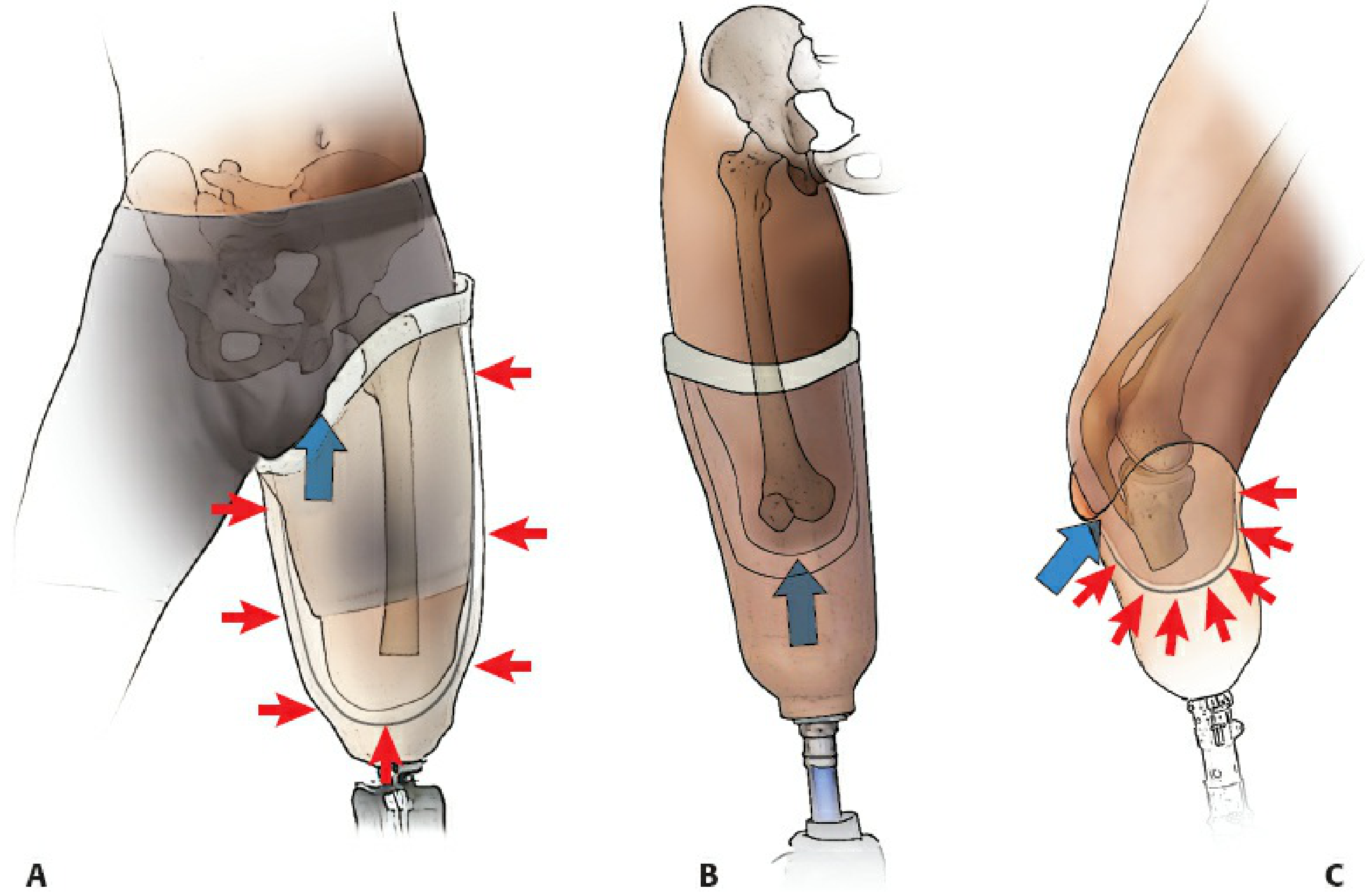
Anatomy of Pressure Distribution: Tolerant vs. Intolerant Areas
The fundamental design of the PTB socket is based on identifying and exploiting pressure-tolerant anatomical zones while relieving pressure-intolerant zones.
Pressure-Tolerant (Weight-Bearing) Areas
These structures can sustain the compressive and shear forces of prosthetic loading:
- Patellar tendon - the primary load-bearing zone, against which the anterior socket brim presses during stance phase (akin to patellar tendon-bearing cast application)
- Medial tibial flare (proximal medial tibial metaphysis) - broad cortical surface amenable to pressure
- Anterior compartment musculature - soft tissue cushion over the anterior tibia
- Gastrocnemius muscle (posterior stump) - well-vascularised, durable soft tissue
- Fibular shaft (mid and proximal portions)
Pressure-Intolerant (Relief) Areas
These must be relieved in the socket to prevent ulceration, pain, and skin breakdown:
- Tibial crest - subcutaneous, sharp bony ridge; most vulnerable to pressure necrosis
- Tibial tubercle - bony prominence directly underlying the patellar tendon insertion
- Distal fibula and fibular head - subcutaneous; fibular head is also vulnerable to peroneal nerve compression
- Common peroneal nerve - as it winds around the fibular head; compression causes peroneal palsy
- Hamstring tendons (semitendinosus, biceps femoris) - posteriorly, where they cross the knee
- Distal stump end - even with well-padded closure, direct end-bearing is not intended and can cause ulceration
As summarised in Miller's Review of Orthopaedics (9th Ed): "Weight bearing by the patellar ligament (or tendon) loads all areas of the residual limb that tolerate weight (patellar tendon, medial tibial flare, anterior compartment, gastrocnemius muscle, and fibular shaft); weight-intolerant areas include the tibial crest and tubercle, distal fibula and fibular head, peroneal nerve, and hamstring tendons."
The PTB Socket: Design and Variants
Classic PTB Socket (Radcliffe-Foort, 1959)
The original PTB socket is a rigid, total-contact design that:
- Has a patellar tendon bar - an anterior brim projection that directly loads the patellar tendon
- Provides relief channels over pressure-intolerant areas (tibial crest, fibular head)
- Is moulded with the knee in slight flexion (5-10°) to facilitate patellar tendon loading
- Uses a soft insert (polyethylene foam or more recently silicone/thermoplastic elastomer) as a liner between the residual limb and rigid outer shell
- Achieves suspension via a supracondylar strap or cuff
The socket attains intimate total contact with the stump, which prevents distal oedema (unlike older plug-fit sockets where distal space allowed venous stasis and verrucous hyperplasia).
Supracondylar (SC) Socket (PTB-SC)
The supracondylar modification extends the medial and lateral brims of the socket above the femoral condyles. The flare of the medial and lateral femoral condyles provides bony lock within the socket for suspension without the need for an external cuff or strap. This variant is particularly useful when:
- The residual limb is shorter than 5 cm (limited lever arm)
- Suspension reliability is a priority (e.g., high-activity patients)
- An external cuff is cosmetically unacceptable
The increased socket height also provides added mediolateral stability at the knee joint.
Supracondylar-Suprapatellar (SC-SP) Socket (PTB-SC-SP)
The supracondylar-suprapatellar socket extends further proximally to enclose the patella, with a proximal bar above the patella. This design:
- Provides the most secure bony suspension of all PTB variants
- Offers excellent mediolateral stability, so no additional straps or cuffs are required
- Is indicated for very short stumps, patients with ligamentous knee instability, and those requiring maximum suspension
- The enclosed patella may restrict some patients; cosmetically more bulky
Miller's Review of Orthopaedics notes: "The patellar tendon-bearing supracondylar/suprapatellar socket has proximal extensions over the distal femoral condyles and patella."
Total Surface Weight Bearing (TSWB) Socket
More recent socket design philosophy has shifted toward total surface weight bearing, in which pressure is distributed more equally across the entire surface of the transtibial residual limb, rather than concentrating forces on specific anatomical zones as in the classic PTB. The interface liner material is critical in TSWB - silicone, thermoplastic elastomer (TPE), or urethane gels conform to the limb surface, distributing load while accommodating volume fluctuations (Miller's Review of Orthopaedics, 9th Ed).
Double-Walled Socket Construction
Modern PTB sockets are typically double-walled:
- Flexible inner socket (thermoplastic, silicone, or TPE) - provides total contact, accommodates volume changes, and protects skin
- Rigid outer shell (carbon fibre, fibreglass, or rigid thermoplastic) - provides structural support and connects to the prosthetic shank and foot
This construction allows the flexible liner to accommodate residual limb volume fluctuations (which are greatest in the first 12-18 months post-amputation) while maintaining structural integrity.
Suspension Systems
Suspension is the mechanism by which the prosthesis is attached to the residual limb and prevented from pistoning (vertical sliding) during swing phase. Various options exist, from proximal to distal:
1. Supracondylar Cuff (Strap)
The original suspension method - a leather or synthetic strap encircling the limb just above the femoral condyles. Simple, cheap, adjustable. Disadvantage: pistoning if not fitted precisely; the strap may be uncomfortable.
2. Supracondylar Bony Lock (SC and SC-SP sockets)
Bony lock within the socket - the condyles prevent the socket from dropping off during swing phase. No external components required.
3. Suction Suspension
An airtight seal between the socket and a silicone liner provides suction to maintain suspension. The liner is rolled onto the residual limb and the socket provides a negative pressure environment. Suction is the primary suspension modality in most modern lower extremity prostheses (Miller's Review of Orthopaedics). Advantages: reduces pistoning, skin shear, and proximal-band pressure. Disadvantage: requires adequate residual limb volume consistency.
4. Elevated Vacuum Suspension
An active vacuum pump draws additional air from the socket, creating greater negative pressure. Reduces pistoning further and may reduce residual limb volume fluctuation. Indicated for highly active (K3-K4) patients.
5. Sleeve Suspension
A silicone or neoprene sleeve is rolled over the junction of the socket brim and the thigh, using friction and negative pressure. Effective but susceptible to sleeve deterioration.
6. Corset (Thigh Corset) Suspension
A leather or plastic thigh corset connected by metal uprights to the socket. The oldest suspension method, now largely obsolete for primary fitters but still used where:
- Knee instability requires lateral support
- Very short stumps provide insufficient purchase for other methods
- Dysvascular patients with fragile skin who cannot tolerate suction
- Resource-limited settings
Disadvantages of corset: thigh atrophy ("disuse atrophy of the thigh"), verrucous hyperplasia of the distal stump (due to pressure gradient), reduced proprioception, poor cosmesis, and increased weight.
Prosthetic Components Distal to the Socket
Shank (Pylon)
Connects the socket to the prosthetic foot. Two designs:
- Endoskeletal (modular): load-bearing central pylon covered by a soft cosmetic foam exterior - the most common modern design. Allows easy adjustment of alignment.
- Exoskeletal (crustacean): hard load-bearing outer shell. More durable but cannot be adjusted easily.
Rotator units may be added for patients engaged in twisting activities (golf, sitting rotation).
Prosthetic Foot
The prosthetic foot is selected based on the patient's activity level (Medicare Functional Classification, K0-K4) and specific demands:
1. Solid Ankle Cushioned Heel (SACH) Foot
The standard non-articulated foot for decades. A rigid keel with a cushioned heel wedge simulates plantar flexion at heel strike. Advantages: durable, low cost, low maintenance. Limitation: no energy return, poor accommodation to uneven terrain. Appropriate for K1 (household) ambulators. Still widely used in resource-limited settings.
2. Single-Axis Foot
An ankle hinge permits dorsiflexion and plantar flexion, facilitating knee stability at heel strike in patients with weak quadriceps. Poor durability and cosmesis limit its use.
3. Multiaxial Foot
Allows motion in all three planes via flexible mechanical joints or keel. Better accommodation to uneven terrain. Recommended for K2 community ambulators.
4. Dynamic Response / Energy-Storing Foot
The most significant advancement in prosthetic foot technology. A carbon fibre leaf-spring keel stores energy during the loading phase and returns it as push-off during late stance - mimicking the biological Achilles-calf complex. Key designs include:
- Seattle Foot
- Carbon Copy II/III
- Flex Foot (with posterior projection for heel strike and split-toe configuration)
- Ceterus Foot (with integrated shock absorber)
Dynamic-response feet permit most normal activities and are recommended for K3-K4 ambulators. Selection depends on patient height, weight, activity level, access to maintenance, cosmesis, and funding (Miller's Review of Orthopaedics, 9th Ed).
5. Microprocessor-Controlled Foot/Ankle
Real-time microprocessor adjustment of ankle dorsiflexion and stiffness based on sensor input. Optimises performance across variable cadence and terrain. Reserved for highly active (K4) patients given cost.
Alignment
Correct alignment of the PTB prosthesis is critical for comfortable, efficient, and safe gait. The process involves:
Bench Alignment
The initial static alignment is set by the prosthetist according to standard geometric principles. For a transtibial prosthesis:
- The socket is flexed 5-10° to facilitate patellar tendon loading and prevent socket brim impingement in the popliteal fossa
- The foot is positioned such that the ground reaction force (GRF) passes approximately through the knee joint centre in the sagittal plane during mid-stance
Dynamic Alignment
Fine-tuned during gait analysis. The patient's gait is observed for:
- Lateral trunk shift (may indicate socket varus/valgus malalignment)
- Knee instability (excessive socket flexion, foot plantar flexion)
- Whip (rotational malalignment at the foot-pylon interface)
- Uneven step length (limb length discrepancy)
Special Considerations
The PTB Cast
Before definitive prosthetic fitting, a patellar tendon bearing cast serves as an interim device for transtibial fractures and post-amputation stump maturation. It is applied as a below-knee cast with a proximal anterior brim moulded over the patellar tendon and relief channels over the tibial crest, allowing weight bearing through the patellar tendon while protecting the healing bone or wound. The CPT code 29435 designates this application.
For tibial diaphyseal fractures treated non-operatively, the PTB cast (after initial long-leg cast immobilisation) enables knee mobilisation and early weight bearing, exploiting Sarmiento's principle that axial loading stimulates fracture healing (Rockwood and Green's, 2025).
Paediatric Considerations
In adolescents with below-knee amputations, the patellar tendon-bearing prosthesis may cause patellar dislocation and patella alta - attributed to chronic upward force on the inferior patellar surface by the prosthetic brim. Elongation of the patellar tendon may result. Earlier modification of the prosthesis to distribute force over a greater area (rather than concentrating it on the patellar tendon) may prevent this complication (Campbell's Operative Orthopaedics, 15th Ed, 2026). Bony overgrowth at the tibial and fibular cut ends is a separate paediatric complication requiring periodic surgical revision.
Vascular Amputees
In dysvascular (peripheral arterial disease, diabetic) patients - who constitute the majority of lower limb amputees - the PTB prosthesis must be fitted with particular care:
- Skin fragility demands meticulous socket fit without pressure point creation
- Total contact is essential to prevent dependent oedema
- Wound care must be integrated into the rehabilitation pathway
- Silicone liners are preferred over hard direct-contact sockets
- Below-knee amputation retains the knee joint, dramatically improving rehabilitation potential and energy expenditure compared with transfemoral amputation
Rehabilitation and Functional Outcomes
Prosthetic rehabilitation follows a structured pathway:
- Pre-operative counselling and goal setting (ideally involving the prosthetist)
- Immediate post-operative phase: rigid dressing or pneumatic post-amputation mobility (PPAM) aid; prevention of flexion contracture at the knee (position in extension)
- Stump maturation: residual limb bandaging in a specific figure-of-eight pattern to shape the stump; volume stabilisation typically takes 6-18 months
- Temporary prosthesis: fitted once wound healed and stump volume stabilising
- Definitive prosthesis: fitted when stump volume is stable; socket replaced as volume changes
- Gait training: initiated with parallel bars, progressing to walking aids, then independent ambulation
- Advanced activities: as dictated by K-level functional classification
The Medicare Functional Classification (K-level) system guides prosthetic prescription:
| K-level | Patient Profile | Foot Recommendation |
|---|---|---|
| K0 | No ambulation potential | Cosmetic only |
| K1 | Household ambulator, fixed cadence | SACH, single-axis |
| K2 | Limited community, low barriers | Multiaxial, flexible keel |
| K3 | Community, variable cadence, barriers | Dynamic response/energy-storing |
| K4 | High activity, sport, high impact | Dynamic response, microprocessor |
Transtibial amputees with a PTB prosthesis have significantly lower energy expenditure during walking compared with transfemoral amputees (approximately 25% increase above normal vs. 65% increase for above-knee), owing to preservation of the knee joint. This underpins the surgical priority of preserving every centimetre of tibial length (Pye's Surgical Handicraft, 22nd Ed).
Complications of the PTB Prosthesis
| Complication | Cause | Management |
|---|---|---|
| Skin ulceration | Pressure point (tibial crest, fibular head) | Socket modification; pressure relief |
| Peroneal nerve palsy | Fibular head compression | Modify socket over fibular head |
| Residual limb oedema (distal) | Poor total contact, pistoning | Improve suspension, total contact insert |
| Verrucous hyperplasia | Distal negative pressure (incomplete contact) | Total contact socket; corset suspension elimination |
| Patella alta / patellar dislocation | PTB brim force concentrated on inferior patella (paediatric) | Redistribute load; modify socket brim |
| Knee flexion contracture | Inadequate post-operative positioning | Extension splinting; physiotherapy |
| Stump neuroma | Nerve end in pressure zone | Buried proximal; surgical excision if symptomatic |
| Socket pistoning | Inadequate suspension | Upgrade to suction/elevated vacuum |
Conclusion
The patellar tendon bearing prosthesis, in its various socket configurations and with its range of modern distal components, is the standard prosthetic rehabilitation solution for the transtibial amputee. Its design rests on a thorough understanding of residual limb anatomy - exploiting pressure-tolerant zones and protecting pressure-intolerant ones - and on the biomechanical principle that weight is transmitted hydrostatically through the socket-residual limb interface rather than through end-bearing. The evolution from the classic PTB to total surface weight-bearing designs, suction suspension, and dynamic-response carbon-fibre feet has progressively improved functional outcomes and quality of life for transtibial amputees. The orthopaedic surgeon's role - to provide the optimal residual limb through sound surgical technique - remains the indispensable prerequisite upon which all subsequent prosthetic rehabilitation depends.
Sources:
- Campbell's Operative Orthopaedics, 15th Edition, 2026 (Chapter 31: Amputations)
- Miller's Review of Orthopaedics, 9th Edition (Chapter 10: Prosthetics)
- Rockwood and Green's Fractures in Adults, 10th Edition, 2025 (Chapter 21: Amputations; Chapter 4: Patellar Tendon-Bearing Cast)
- Pye's Surgical Handicraft, 22nd Edition (Chapter 25: Amputations)
- Pfenninger and Fowler's Procedures for Primary Care, 3rd Edition (PTB Cast Application)
Essay on patellar tendon bearing prostheses for orthopaedic postgraduate exam
I just wrote this essay in full detail in the previous response. Rather than repeating it identically, here is the complete essay again for your convenience:
Patellar Tendon Bearing Prosthesis
Introduction
The patellar tendon bearing (PTB) prosthesis is the foundational device for rehabilitation of the transtibial (below-knee) amputee. Introduced by Radcliffe and Foort at the University of California, Berkeley in 1959, it represented a paradigm shift from the older total-contact thigh-corset with metal side bars to a self-suspending, below-knee socket that transferred weight primarily through the patellar tendon and other pressure-tolerant areas of the residual limb. Over six decades later, the PTB concept - and its derivatives - remain central to transtibial prosthetic practice, and understanding its principles, variants, components, and clinical application is essential for the postgraduate orthopaedic surgeon.
The Transtibial Residual Limb: Surgical Prerequisites
The quality and geometry of the residual limb directly determines prosthetic success.
Residual Limb Length
The tibial resection is planned so that the residual tibia is approximately 2.5 cm for every 30 cm of patient height, equating to approximately 15-17 cm measured from the tibial plateau (Rockwood and Green's, 10th Ed, 2025). This length provides an adequate lever arm to drive the prosthesis, sufficient soft tissue coverage over the distal bone end, and clearance for prosthetic ankle-foot components.
Skin Flaps
The Burgess long posterior myoplastic flap is the most widely used technique. The gastrocnemius-based posterior flap is brought anteriorly to cover the distal tibia, placing the suture line away from the weight-bearing surface over the patellar tendon. The tibial crest is bevelled at 45 degrees anteriorly, and the fibula is resected 1-2 cm shorter than the tibia to prevent distal bony prominence.
Muscle Balancing
Myodesis (direct muscle-to-bone fixation via drill holes) or myoplasty (opposing muscle group attachment) maintains muscle bulk, prevents atrophy, facilitates venous return via the muscular pump, and restores functional tension in the posterior compartment muscles. Without adequate myodesis, stump atrophy impairs socket fit progressively.
Neurovascular Management
All nerves are placed under gentle traction, cut cleanly, and buried in muscle tissue away from bony prominences and weight-bearing zones to minimise neuroma formation in pressure areas. Vessels are secured with suture ligature.
Principle of Weight Transfer
In the PTB prosthesis, weight is NOT transferred through the transected end of the tibia. Forces are distributed hydrostatically throughout the residual limb-socket interface. The socket is moulded for the knee to be at approximately 5-10 degrees of flexion, permitting weight bearing through the patellar tendon - described as "a comfortable arrangement similar to kneeling" (Rockwood and Green's, 2025).
Anatomy of Pressure Distribution: Tolerant vs. Intolerant Areas
The fundamental design logic of the PTB socket is based on identifying and exploiting pressure-tolerant anatomical zones while relieving pressure-intolerant zones.
Pressure-Tolerant (Weight-Bearing) Areas
- Patellar tendon - the primary load-bearing zone; the anterior socket brim presses directly against it during stance
- Medial tibial flare - broad, cortical surface of the proximal medial tibial metaphysis
- Anterior compartment musculature - soft tissue cushion over the anterior tibia
- Gastrocnemius muscle - posteriorly, well-vascularised and durable
- Fibular shaft (mid and proximal portions)
Pressure-Intolerant (Relief) Areas
- Tibial crest - subcutaneous, sharp; most vulnerable to pressure necrosis
- Tibial tubercle - prominent insertion of the patellar tendon; paradoxically relieved despite proximity to the loading zone
- Distal fibula and fibular head - subcutaneous prominences
- Common peroneal nerve - as it winds around the fibular neck; compression causes peroneal palsy
- Hamstring tendons - posteriorly at the popliteal crease
- Distal stump end - direct end-bearing is not intended and causes skin ulceration
As summarised by Miller's Review of Orthopaedics (9th Ed): "Weight bearing by the patellar ligament (or tendon) loads all areas of the residual limb that tolerate weight - patellar tendon, medial tibial flare, anterior compartment, gastrocnemius muscle, and fibular shaft; weight-intolerant areas include the tibial crest and tubercle, distal fibula and fibular head, peroneal nerve, and hamstring tendons."
PTB Socket: Design and Variants
1. Classic PTB Socket (Radcliffe-Foort, 1959)
The original rigid total-contact socket with:
- Patellar tendon bar - anterior brim projection that directly loads the patellar tendon
- Relief channels over pressure-intolerant areas (tibial crest, fibular head, peroneal nerve)
- Soft insert liner between stump and rigid shell
- Suspension via a supracondylar cuff/strap
- Knee positioned in 5-10° flexion during fabrication
Total contact prevents the distal oedema and verrucous hyperplasia that plagued older "plug-fit" sockets where a distal air space allowed venous stasis.
2. Supracondylar (PTB-SC) Socket
The medial and lateral socket brims extend above the femoral condyles. The condylar flare provides a bony lock for self-suspension without an external strap. Indications:
- Residual limb shorter than 5 cm (limited lever arm)
- High-activity patients requiring reliable suspension
- Patients who find the cuff cosmetically unacceptable
- Added mediolateral knee stability required
3. Supracondylar-Suprapatellar (PTB-SC-SP) Socket
Further proximal extension to enclose the patella with a proximal bar above it. This provides:
- Maximum bony suspension - no straps or cuffs required
- Excellent mediolateral stability
- Best suited to very short stumps and knees with ligamentous laxity
Miller's Review: "The patellar tendon-bearing supracondylar/suprapatellar socket has proximal extensions over the distal femoral condyles and patella."
4. Total Surface Weight Bearing (TSWB) Socket
Modern philosophy distributes pressure equally across the entire surface of the residual limb rather than concentrating it on the patellar tendon zone. Interface liner materials (silicone, thermoplastic elastomer/TPE, urethane gel) conform to the limb surface, distribute load, and accommodate volume fluctuations. Total contact reduces oedema by providing uniform hydrostatic support.
5. Double-Walled Socket Construction
The modern standard:
- Flexible inner socket (thermoplastic/silicone/TPE) - total contact, protects skin, accommodates volume changes
- Rigid outer shell (carbon fibre, fibreglass, rigid thermoplastic) - structural support, connects to distal components
Suspension Systems
Suspension prevents pistoning (vertical sliding during swing phase):
| Suspension Type | Mechanism | Best Use |
|---|---|---|
| Supracondylar cuff/strap | External strap above condyles | Standard; simple, cheap |
| Supracondylar bony lock | Condylar flare within SC/SC-SP socket | Short stumps; no external hardware |
| Suction (pin-lock or sealing liner) | Negative pressure between liner and socket | Standard for modern active patients |
| Elevated vacuum | Active pump increases negative pressure | K3-K4; reduces pistoning and oedema |
| Sleeve suspension | Silicone/neoprene sleeve over socket brim | Good; susceptible to sleeve wear |
| Thigh corset + uprights | Proximal mechanical attachment | Legacy; used for very short stumps, fragile skin, knee instability |
The thigh corset suspension is largely obsolete as primary suspension but remains in use in resource-limited settings and for specific indications. Its well-documented disadvantages include: thigh atrophy, verrucous hyperplasia of the distal stump, poor proprioception, excess weight, and poor cosmesis.
Prosthetic Components Distal to the Socket
Shank (Pylon)
- Endoskeletal (modular): load-bearing central pylon with soft cosmetic foam exterior - the dominant modern design; allows easy alignment adjustment
- Exoskeletal: hard outer load-bearing shell; more durable but non-adjustable
Rotator units are added for patients with rotational activity demands (golf, pivoting sports).
Prosthetic Feet
Foot selection is guided by the Medicare Functional Classification (K-level):
SACH Foot (Solid Ankle Cushioned Heel)
- Non-articulated; rigid keel with cushioned heel wedge
- Simulates plantar flexion at heel strike via heel compression
- Standard for K1 (household) ambulators
- Advantages: low cost, durable, low maintenance
- Limitation: no energy return; poor terrain accommodation
Single-Axis Foot
- Hinge allows dorsiflexion/plantar flexion
- Aids knee stability at heel strike in weak quadriceps
- K1 patients with stability concerns; poor durability limits widespread use
Multiaxial Foot
- Three-plane motion via flexible keel or joints
- Better accommodation to uneven terrain
- K2 (limited community) ambulators
Dynamic Response / Energy-Storing Foot
- Carbon fibre leaf-spring keel stores energy during loading phase; returns it as push-off during late stance
- Mimics the biological Achilles-calf mechanism
- Key designs: Seattle Foot, Carbon Copy II/III, Flex Foot, Ceterus Foot (with integrated shock absorber)
- K3-K4 ambulators; enables variable cadence and most normal activities
- Selection based on patient height, weight, activity level, and funding
Microprocessor-Controlled Ankle/Foot
- Real-time sensor-driven adjustment of stiffness and dorsiflexion
- K4 (high-impact) patients; expensive
| K-Level | Profile | Foot | Knee |
|---|---|---|---|
| K0 | No ambulation potential | Cosmetic only | - |
| K1 | Household, fixed cadence | SACH, single-axis | Manual locking |
| K2 | Limited community, low barriers | Multiaxial, flexible keel | Weight-activated |
| K3 | Community, variable cadence | Dynamic response/energy-storing | Hydraulic/pneumatic |
| K4 | High activity/sport | Dynamic response, microprocessor | Microprocessor |
Alignment
Bench Alignment
Static initial alignment by the prosthetist:
- Socket in 5-10° flexion to facilitate patellar tendon loading
- Ground reaction force passes approximately through the knee joint centre in mid-stance
- Foot aligned parallel to the contralateral foot
Dynamic Alignment
Observational gait analysis fine-tunes alignment. Gait deviations corrected include:
- Lateral trunk shift (varus/valgus socket)
- Knee instability (excessive socket flexion or foot plantar-flexion)
- Whip at toe-off (rotational malalignment at pylon-foot interface)
- Step length asymmetry (limb length error)
The PTB Cast: Non-Prosthetic Application
The PTB principle extends to the patellar tendon-bearing cast used for:
- Tibial diaphyseal fractures (non-operative management): after initial long-leg cast immobilisation, a PTB cast allows knee mobilisation and early weight bearing while protecting the fracture. This exploits Sarmiento's principle that axial loading stimulates fracture healing through periosteal callus formation.
- Post-amputation stump shaping: rigid dressings incorporating PTB principles help shape and mature the residual limb.
The PTB cast has an anterior brim moulded against the patellar tendon with relief channels over the tibial crest - identical principles to the prosthetic socket (CPT 29435).
Special Considerations
Paediatric Amputees
In adolescents with below-knee amputations, the PTB prosthesis may cause patellar dislocation and patella alta due to the upward force of the prosthetic brim concentrated on the inferior patellar surface. Elongation of the patellar tendon may result. Earlier redistribution of force over a broader area of the socket brim may prevent this complication (Campbell's Operative Orthopaedics, 15th Ed, 2026).
Bony overgrowth of the tibial and fibular cut ends - a separate and common paediatric complication - is not prevented by epiphysiodesis and requires periodic surgical revision.
Vascular and Diabetic Amputees
- Constitute the majority of lower limb amputees
- Skin fragility requires meticulous socket fit without focal pressure concentration
- Silicone liners preferred over hard direct-contact sockets
- Below-knee amputation (vs. above-knee) preserves the knee joint, reducing energy expenditure during walking by ~40% and dramatically improving rehabilitation potential
- The PTB prosthesis is specifically associated with high rates of successful community ambulation in this group
Complications
| Complication | Cause | Management |
|---|---|---|
| Skin ulceration | Pressure point on tibial crest or fibular head | Socket relief modification |
| Peroneal nerve palsy | Fibular head compression | Relieve fibular head in socket |
| Distal stump oedema | Inadequate total contact | Total contact insert; improve suspension |
| Verrucous hyperplasia | Distal negative pressure (suction effect from poor contact) | Total contact socket; eliminate corset |
| Patella alta / dislocation | PTB brim upward force on inferior patella (paediatric) | Redistribute load; modify brim |
| Knee flexion contracture | Inadequate post-operative positioning | Extension splinting; physiotherapy |
| Stump neuroma | Nerve end in pressure zone | Surgical relocation; re-bury proximally |
| Socket pistoning | Inadequate suspension | Upgrade to suction/elevated vacuum |
| Skin maceration / infection | Moisture retention in liner | Liner hygiene protocol; antibacterial liners |
Rehabilitation Pathway
- Pre-operative: Counselling, goal setting; prosthetist input on optimal stump length
- Immediate post-operative (0-2 weeks): Rigid dressing or pneumatic post-amputation mobility (PPAM) aid; knee maintained in extension to prevent flexion contracture; drain for 24-48 hours
- Stump maturation (weeks 2 - months 6-18): Figure-of-eight bandaging; volume stabilisation; physiotherapy for strengthening and proprioception
- Temporary prosthesis: Fitted once wound healed and volume stabilising; allows gait training and builds socket tolerance
- Definitive PTB prosthesis: Fabricated when volume stable; replaced as volume changes
- Gait training: Parallel bars → walking aids → independent ambulation
- Advanced rehabilitation: Sport-specific training; K4 prosthetic components where indicated
Energy Expenditure
One of the most clinically important advantages of the below-knee amputation with PTB prosthesis over transfemoral amputation is the significantly lower energy cost of walking:
- Normal walking: baseline
- Transtibial amputee with PTB prosthesis: approximately 25% increased energy expenditure
- Transfemoral amputee: approximately 65% increased energy expenditure
- Bilateral transtibial: approximately 40% increased energy expenditure
This energetic advantage - attributable entirely to preservation of the knee joint - is why every centimetre of tibial length is surgically precious, and why below-knee amputation is strongly preferred over above-knee whenever tissue viability permits.
Conclusion
The patellar tendon bearing prosthesis, grounded in the anatomical reality of the transtibial residual limb, applies force through pressure-tolerant zones while meticulously protecting pressure-intolerant structures. The classic PTB socket has evolved into a family of designs - supracondylar, supracondylar-suprapatellar, and total surface weight bearing - coupled with increasingly sophisticated suspension systems and prosthetic feet that restore near-normal gait at dramatically lower energy cost than above-knee alternatives. The orthopaedic surgeon must understand not only the surgical technique for creating an optimal residual limb but also the prosthetic principles that will determine long-term functional outcomes - the two are inseparable.
Sources:
- Campbell's Operative Orthopaedics, 15th Edition, 2026 (Chapter 31: Amputations in Children)
- Miller's Review of Orthopaedics, 9th Edition (Chapter 10: Prosthetics and Orthotics)
- Rockwood and Green's Fractures in Adults, 10th Edition, 2025 (Chapter 21: Technical Considerations of Limb Amputation; Chapter 4: PTB Cast)
- Pye's Surgical Handicraft, 22nd Edition (Chapter 25: Amputations)
- Pfenninger and Fowler's Procedures for Primary Care, 3rd Edition (CPT 29435: PTB Cast Application)
Nitrogen metabolism and purine, pyramidine relation
Finding Sources
Finding Sources
Finding Sources
Reading File
Reading File
Finding Sources
Reading File
Reading File
Reading File
Reading File
Reading File
Finding Sources
Reading File
Reading File
Loading Image
Loading Image
Loading Image
Loading Image
I have all the content and diagrams needed. Here is the comprehensive essay with images:
Nitrogen Metabolism and Its Relationship to Purine and Pyrimidine Synthesis
Introduction
Nitrogen is a defining element of life. While carbon, hydrogen, and oxygen form the backbone of all organic molecules, nitrogen is uniquely concentrated in the functional molecules of biology - amino acids, proteins, nucleotides, and nucleic acids. The metabolism of nitrogen in the human body encompasses three interconnected domains: (1) the handling of amino acid nitrogen through transamination, oxidative deamination, and urea synthesis; (2) the de novo biosynthesis of purine and pyrimidine nucleotides, which requires nitrogen donated by amino acids; and (3) the degradation and salvage of purines and pyrimidines, which returns nitrogenous products to either the nucleotide pool or to excretable end products. These pathways are tightly integrated, and dysfunction at any node - whether inherited or acquired - manifests as disease.
Part I: Nitrogen Metabolism - Overview and Core Pathways
1. Sources of Nitrogen
Dietary protein is the primary exogenous nitrogen source. After digestion in the gut, amino acids are absorbed and transported to the liver via the portal vein. In the fed state, most amino acids are used for protein synthesis; excess amino acids are catabolised, with their nitrogen ultimately excreted as urea via the kidneys. The carbon skeletons are converted to intermediates of glycolysis or the TCA cycle for energy or storage (Basic Medical Biochemistry, 6th Ed).
During fasting, muscle protein is mobilised. The nitrogen from muscle amino acid catabolism is not excreted directly but is shuttled to the liver in the form of alanine (via the glucose-alanine cycle) and glutamine (the primary non-toxic ammonia carrier in the blood).
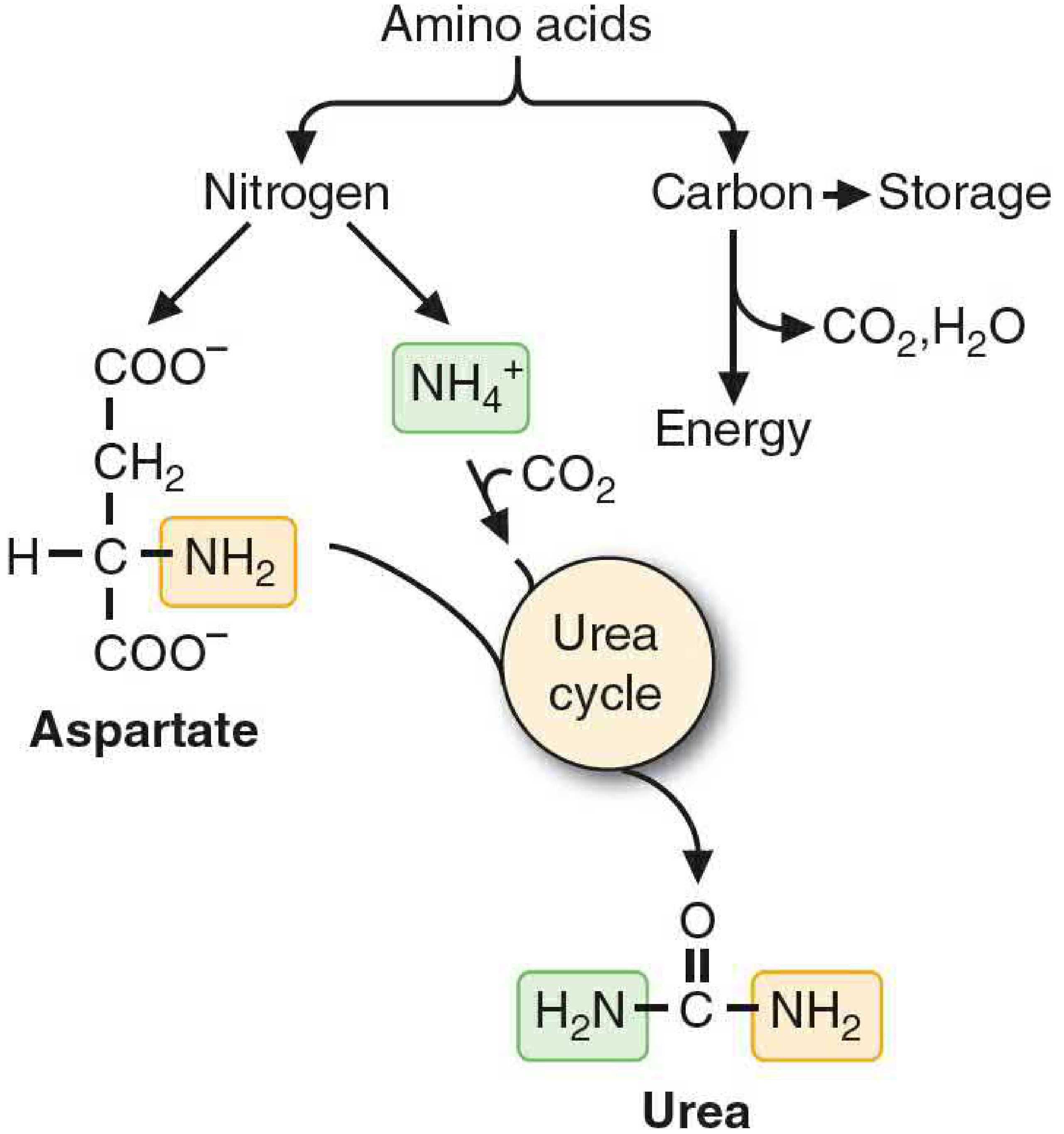
2. Transamination
The first step in catabolising most amino acids is transamination - transfer of the α-amino group to α-ketoglutarate, producing glutamate and the corresponding α-keto acid. The enzymes catalysing these reactions are aminotransferases (transaminases), which use pyridoxal phosphate (PLP, vitamin B6) as cofactor. Key examples:
- Alanine + α-ketoglutarate → Pyruvate + Glutamate (ALT/GPT)
- Aspartate + α-ketoglutarate → Oxaloacetate + Glutamate (AST/GOT)
Glutamate thus acts as the central nitrogen collector, receiving amino groups from virtually all amino acids before they are released as ammonia.
3. Oxidative Deamination: Glutamate Dehydrogenase
Glutamate is oxidatively deaminated in liver mitochondria by glutamate dehydrogenase (GDH):
Glutamate + NAD⁺ (or NADP⁺) → α-Ketoglutarate + NH₄⁺ + NADH
This reaction is the primary route by which amino group nitrogen is released as free ammonium ion (NH₄⁺) for entry into the urea cycle. GDH is the only mammalian enzyme with significant reversibility in nitrogen metabolism - it can both release and fix ammonia. It is allosterically regulated: activated by ADP and GDP (low energy state signals: generate more TCA cycle intermediates) and inhibited by ATP and GTP.
GDH is one of only four enzymes that can "fix" ammonia into organic molecules; the others are glutamine synthetase, carbamoyl phosphate synthetase I (CPS I), and glycine cleavage enzyme (glycine synthase) (Basic Medical Biochemistry, 6th Ed).
4. Ammonia Transport and Toxicity
Free ammonia is highly toxic - concentrations above normal are neurotoxic (mechanism involves depletion of α-ketoglutarate, impairment of TCA cycle, and altered neurotransmitter metabolism). Therefore, ammonia is transported in the blood in non-toxic form:
- Glutamine: synthesised in most tissues by glutamine synthetase (glutamate + NH₃ + ATP → glutamine). The dominant ammonia-transport molecule from peripheral tissues to the liver and kidneys.
- Alanine: synthesised in muscle via transamination of pyruvate. Carries nitrogen to the liver while simultaneously delivering gluconeogenic substrate (glucose-alanine cycle).
In the kidney, glutamine releases NH₄⁺ into the urine via glutaminase - an important mechanism for acid-base regulation (NH₄⁺ acts as a urinary buffer).
5. The Urea Cycle
The urea cycle (Krebs-Henseleit cycle) is the principal pathway for nitrogen excretion in humans. It operates primarily in hepatocytes and converts the highly toxic ammonia into urea - a non-toxic, water-soluble molecule excreted in urine. The cycle has two nitrogen inputs and produces one molecule of urea:
Two sources of nitrogen in urea:
- NH₄⁺ (from glutamate dehydrogenase reaction) - incorporated first as carbamoyl phosphate
- Aspartate (the second nitrogen donor, entering the cycle directly)
Steps of the Urea Cycle:
Step 1 - Carbamoyl phosphate synthesis (mitochondria)
NH₄⁺ + HCO₃⁻ + 2 ATP → Carbamoyl phosphate (CPS I)
- Occurs in mitochondrial matrix
- Requires N-acetylglutamate (NAG) as obligatory allosteric activator
- Rate-limiting step; irreversible
- CPS I uses nitrogen from free NH₄⁺
- (Note: CPS II, the cytosolic isoform, uses nitrogen from glutamine and produces carbamoyl phosphate for pyrimidine synthesis - a critical distinction)
Step 2 - Citrulline formation (mitochondria)
Carbamoyl phosphate + Ornithine → Citrulline (ornithine transcarbamoylase, OTC)
- OTC is the most commonly deficient urea cycle enzyme (X-linked)
- Citrulline exits mitochondria in exchange for ornithine
Step 3 - Argininosuccinate synthesis (cytosol)
Citrulline + Aspartate + ATP → Argininosuccinate (argininosuccinate synthetase)
- Aspartate donates the second nitrogen atom here
- Driven by ATP hydrolysis to AMP + pyrophosphate
Step 4 - Argininosuccinate cleavage (cytosol)
Argininosuccinate → Arginine + Fumarate (argininosuccinate lyase)
- Fumarate enters the TCA cycle (via cytoplasmic fumarase → malate → oxaloacetate → transaminated back to aspartate, regenerating the nitrogen donor)
Step 5 - Urea formation (cytosol)
Arginine + H₂O → Urea + Ornithine (arginase)
- Ornithine re-enters mitochondria to complete the cycle
- Urea is excreted by the kidneys
Net reaction: NH₃ + CO₂ + Aspartate + 3 ATP → Urea + Fumarate + 2 ADP + AMP + 4 Pᵢ
Regulation: The urea cycle is induced by high-protein diets and fasting (increased enzyme expression). Acute allosteric regulation is achieved via NAG (synthesised from acetyl-CoA and glutamate by NAG synthase, activated by arginine).
Part II: Nucleotide Structure and Nitrogen Content
Before exploring purine and pyrimidine synthesis, it is important to appreciate why these pathways depend so heavily on nitrogen metabolism.
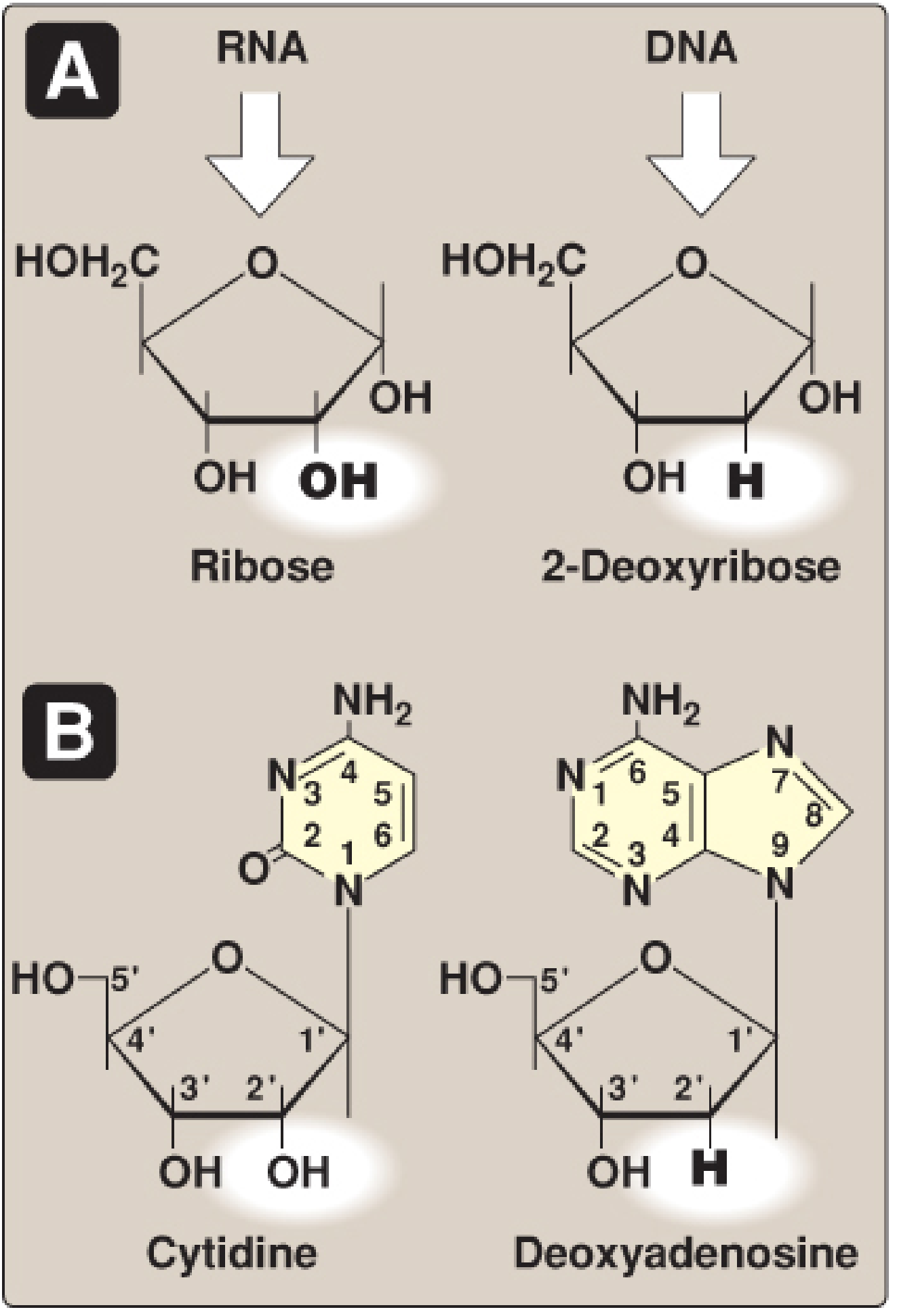
A nucleotide = nitrogenous base + pentose sugar + 1-3 phosphate groups.
- Purines: Adenine (A) and Guanine (G) - bicyclic ring system with 4 nitrogen atoms
- Pyrimidines: Cytosine (C), Uracil (U), Thymine (T) - monocyclic ring with 2 nitrogen atoms
The nitrogen-richness of purine and pyrimidine rings explains why their de novo synthesis draws so heavily from amino acids as nitrogen donors.
Part III: De Novo Purine Synthesis
Purines are synthesised de novo primarily in the liver. Critically, the purine ring is built on a pre-formed ribose-5-phosphate scaffold - the ring is assembled atom-by-atom on PRPP, ultimately forming inosine monophosphate (IMP) as the common intermediate (Lippincott Biochemistry, 8th Ed).
Nitrogen Donors for Purine Ring Atoms
The 9 atoms of the purine ring are donated by several sources:
| Position | Atom | Donor |
|---|---|---|
| N1 | Nitrogen | Aspartate |
| C2 | Carbon | N¹⁰-formyltetrahydrofolate (folate-dependent) |
| N3 | Nitrogen | Glutamine (amide nitrogen) |
| C4 | Carbon | Glycine |
| C5 | Carbon | Glycine |
| N7 | Nitrogen | Glycine |
| C6 | Carbon | CO₂ |
| N9 | Nitrogen | Glutamine (amide nitrogen) |
| C8 | Carbon | N¹⁰-formyltetrahydrofolate |
Key point: Glycine donates its entire molecule (C4, C5, and N7 of the purine ring). Glutamine donates nitrogen at N3 and N9. Aspartate donates nitrogen at N1. CO₂ contributes C6. N¹⁰-formyl-THF contributes C2 and C8.
PRPP: The Activated Scaffold
5-Phosphoribosyl-1-pyrophosphate (PRPP) is synthesised from ribose-5-phosphate (from the pentose phosphate pathway) + ATP by PRPP synthetase:
Ribose-5-phosphate + ATP → PRPP + AMP
PRPP is the essential activated pentose for both purine and pyrimidine synthesis, as well as the salvage reactions. PRPP synthetase is:
- Activated by inorganic phosphate
- Inhibited by purine nucleotides (end-product inhibition)
- X-linked gene
The Committed Step: GPAT Reaction
The committed step of de novo purine synthesis is:
PRPP + Glutamine → Phosphoribosylamine + Glutamate + PPᵢ (catalysed by glutamine phosphoribosylpyrophosphate amidotransferase, GPAT)
GPAT is:
- Inhibited by AMP and GMP (end-product feedback inhibition)
- Activated by PRPP (high PRPP signals need for more purines)
After the GPAT step, 10 further reactions (requiring ATP, glutamine, aspartate, glycine, CO₂, and folate derivatives) build the purine ring, ultimately producing IMP (inosine monophosphate).
IMP to AMP and GMP (Cross-Regulation)
- IMP → AMP requires GTP (fumarate is released; aspartate donates N6)
- IMP → GMP requires ATP (glutamine amide donates N2)
This reciprocal requirement ensures balanced production: excess AMP inhibits its own synthesis and stimulates GMP production (via GTP requirement), and vice versa.
Energy Cost
De novo purine synthesis is expensive: 6 molecules of ATP are consumed per purine nucleotide synthesised.
Part IV: De Novo Pyrimidine Synthesis
Pyrimidines differ fundamentally from purines in their biosynthetic strategy: the pyrimidine ring is synthesised first as a free base (orotate) and then attached to PRPP, rather than being built on PRPP from the start.
Nitrogen Donors for the Pyrimidine Ring
The pyrimidine ring (C-N-C-N) has two nitrogen atoms:
- N1: from Aspartate (the entire aspartate molecule enters the ring)
- N3: from Glutamine (amide nitrogen, via CPS II)
- C2: from CO₂ (via CPS II reaction)
- C4, C5, C6: from Aspartate
Key Enzymatic Steps
Step 1 - Carbamoyl phosphate synthesis (CPS II, cytosol)
Glutamine + CO₂ + ATP → Carbamoyl phosphate
- CPS II (cytosolic) uses glutamine nitrogen - distinct from CPS I (mitochondrial) which uses free NH₄⁺ for the urea cycle
- CPS II activity is the regulated step; inhibited by UTP (end product), activated by PRPP
Step 2 - Condensation with aspartate
Carbamoyl phosphate + Aspartate → Carbamoyl aspartate (aspartate transcarbamoylase, ATCase)
Steps 3-6 - Ring closure to orotate
Carbamoyl aspartate → Dihydroorotate → Orotate (dihydroorotase, dihydroorotate dehydrogenase)
- In mammals, the first three enzymes (CPS II, ATCase, dihydroorotase) are present as a single trifunctional enzyme: CAD
- Dihydroorotate dehydrogenase is located on the inner mitochondrial membrane
Step 5 - Attachment to PRPP
Orotate + PRPP → Orotidine monophosphate (OMP) (orotate phosphoribosyltransferase, OPRT)
Step 6 - Decarboxylation to UMP
OMP → UMP (orotidine-5'-phosphate decarboxylase, ODC)
- OPRT and ODC are also present as a bifunctional enzyme: UMP synthase
UMP is then phosphorylated to UDP and UTP. CTP is synthesised from UTP by CTP synthetase, using glutamine as the nitrogen donor.
Pyrimidines for DNA: dTMP Synthesis
- dUMP → dTMP via thymidylate synthase (TS), which uses N⁵,N¹⁰-methylene-THF as the methyl donor
- This reaction oxidises THF to dihydrofolate (DHF); DHF reductase (DHFR) regenerates THF
- 5-Fluorouracil (5-FU) inhibits TS (suicide inhibitor); Methotrexate inhibits DHFR - both are anticancer drugs exploiting this pathway
Part V: The Critical Intersection - Carbamoyl Phosphate at the Crossroads
The most elegant biochemical example of the connection between nitrogen metabolism and nucleotide synthesis is the dual role of carbamoyl phosphate:
| Feature | CPS I (Mitochondrial) | CPS II (Cytosolic) |
|---|---|---|
| Location | Mitochondrial matrix | Cytosol |
| Nitrogen donor | Free NH₄⁺ | Glutamine |
| Activator | N-acetylglutamate (NAG) | PRPP |
| Inhibitor | - | UTP |
| Product use | Urea cycle | Pyrimidine synthesis |
When ornithine transcarbamoylase (OTC) is deficient (the most common urea cycle defect, X-linked), carbamoyl phosphate that cannot enter the urea cycle overflows into the cytosol, flooding the pyrimidine synthesis pathway. The intermediate orotate accumulates and is excreted in large quantities in the urine (orotic aciduria) - a diagnostic hallmark of OTC deficiency (Basic Medical Biochemistry, 6th Ed).
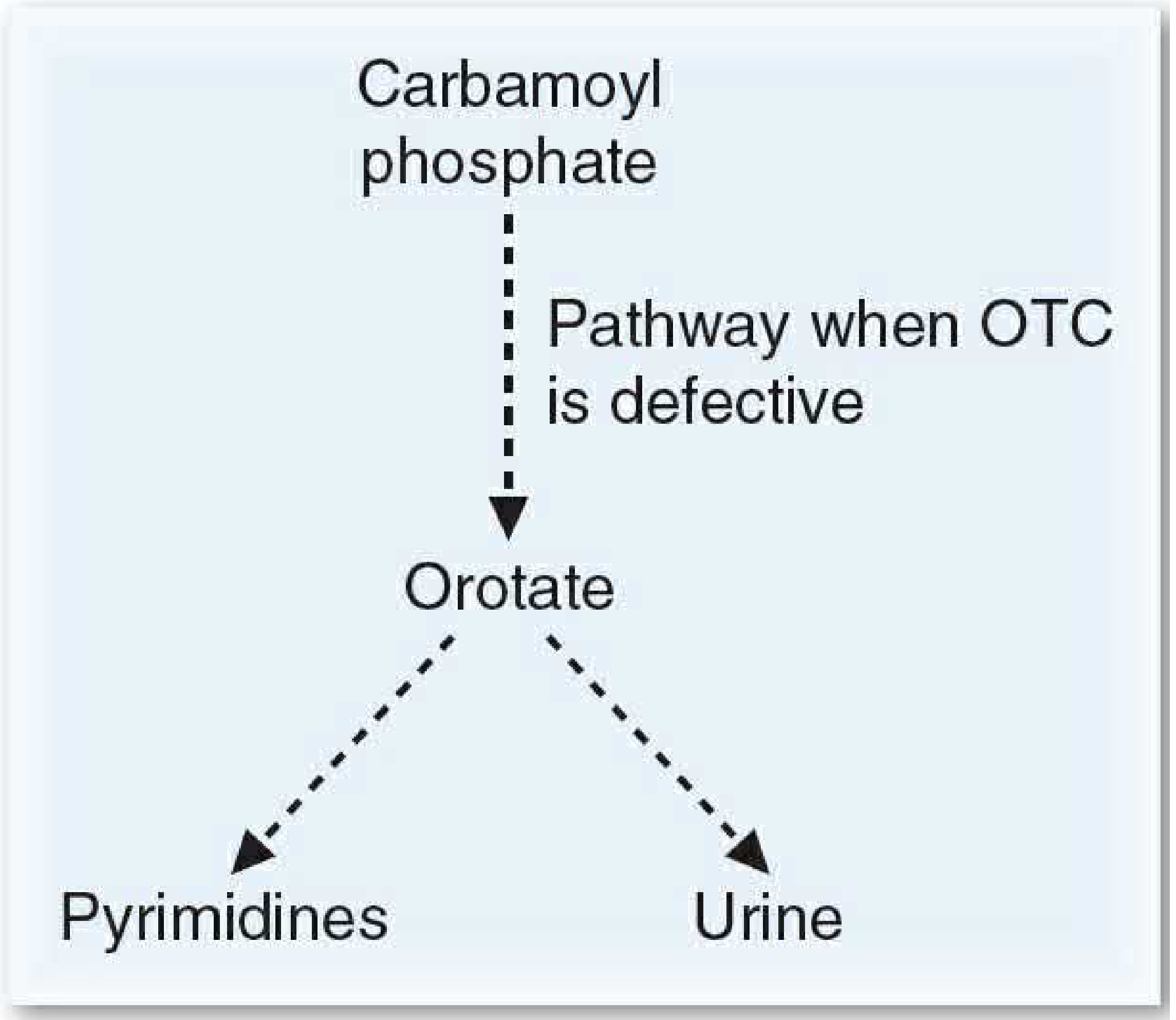
Part VI: PRPP - The Central Hub Linking Both Pathways
PRPP occupies a uniquely central position in nucleotide metabolism:
- Required for de novo purine synthesis (GPAT reaction)
- Required for pyrimidine attachment to ribose (orotate + PRPP → OMP)
- Required for purine and pyrimidine salvage reactions
- Regulated by purine nucleotide concentrations (product inhibition)
Any perturbation of PRPP availability affects both purine and pyrimidine synthesis simultaneously.
Part VII: Purine Salvage Pathway
Purines from nucleic acid turnover (or diet) are recovered rather than degraded, a process that is energetically far more efficient than de novo synthesis.
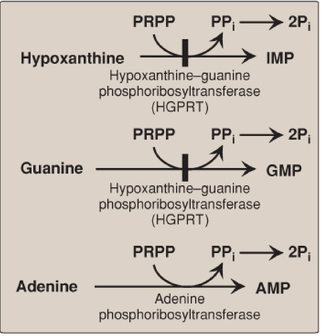
Two enzymes:
- HGPRT (hypoxanthine-guanine phosphoribosyltransferase, X-linked): salvages hypoxanthine → IMP and guanine → GMP
- APRT (adenine phosphoribosyltransferase): salvages adenine → AMP
Both reactions: Base + PRPP → Nucleoside-5'-monophosphate + PPᵢ (irreversible - PPᵢ hydrolysis pulls forward)
Salvage is particularly important in the brain, which has limited capacity for de novo synthesis.
Lesch-Nyhan Syndrome
Complete deficiency of HGPRT (X-linked recessive) causes:
- Inability to salvage hypoxanthine and guanine → both degraded to uric acid
- Elevated PRPP (not consumed by salvage) → increased de novo purine synthesis → more uric acid
- Decreased IMP/GMP → less feedback inhibition of GPAT → further increased de novo synthesis
Consequences: severe hyperuricaemia, gouty arthritis, uric acid urolithiasis, intellectual disability, spasticity, and pathognomonic self-mutilation behaviour (biting of lips and fingers).
Part VIII: Purine Degradation and Gout
Purines (from nucleic acid turnover and de novo synthesis) are degraded via a common pathway:
- AMP → Inosine → Hypoxanthine → Xanthine → Uric acid (xanthine oxidase, XO)
- GMP → Guanosine → Guanine → Xanthine → Uric acid (XO)
Uric acid is the final, insoluble end product of purine degradation in humans (unlike most mammals, which have uricase to further degrade uric acid to allantoin). Normal serum uric acid is close to its saturation point (approximately 6.5 mg/dL). When uric acid levels rise above this (hyperuricaemia), monosodium urate (MSU) crystals precipitate in joints and soft tissues, causing gout.
Pyrimidines, in contrast, are degraded to highly water-soluble products - β-alanine (from CMP/UMP), β-aminoisobutyrate (from TMP), ammonia, and CO₂ - and do not cause crystalline deposition disorders.
Gout - Biochemical Basis
Causes of hyperuricaemia:
- Overproduction: HGPRT deficiency (Lesch-Nyhan), PRPP synthetase overactivity, high purine diet (meat, shellfish), excessive cell turnover (haematological malignancies, chemotherapy)
- Underexcretion (90% of primary gout): reduced renal urate excretion; alcohol and certain drugs (thiazides, low-dose aspirin) impair urate secretion
Treatment:
- Acute attack: anti-inflammatory agents (colchicine, NSAIDs, corticosteroids). Colchicine prevents microtubule polymerisation, reducing neutrophil migration into the joint.
- Long-term (urate-lowering):
- Allopurinol: structural analogue of hypoxanthine; inhibits XO → accumulation of hypoxanthine and xanthine (more soluble than uric acid). Allopurinol is oxidised by XO to oxypurinol, a long-lived XO inhibitor (suicide substrate mechanism). In patients with normal HGPRT, hypoxanthine is salvaged back → reduces PRPP levels → reduces de novo purine synthesis (double benefit).
- Febuxostat: non-purine XO inhibitor
- Uricosuric agents (probenecid, sulfinpyrazone): increase renal uric acid excretion (for underexcretors)
Part IX: Deoxyribonucleotides - Reduction of Ribonucleotides
DNA synthesis requires 2'-deoxyribonucleotides. These are produced from ribonucleoside diphosphates by ribonucleotide reductase (RNR) during the S phase of the cell cycle:
Ribonucleoside diphosphate (ADP, GDP, CDP, UDP) → Deoxyribonucleoside diphosphate (dADP, dGDP, dCDP, dUDP)
RNR is a dimer (R1 + R2 subunits); the reducing equivalents come from thioredoxin, which is regenerated by thioredoxin reductase using NADPH. RNR is extensively regulated (two allosteric sites) to maintain balanced dNTP pools for DNA synthesis.
Hydroxyurea inhibits RNR by scavenging the tyrosyl radical on the R2 subunit - used in cancer and sickle cell disease.
Part X: Clinical Connections and Pharmacological Exploitation
The deep links between nitrogen metabolism and nucleotide synthesis are exploited pharmacologically:
| Drug | Target | Pathway Disrupted |
|---|---|---|
| Methotrexate | DHFR | Folate-dependent steps in both purine and pyrimidine (dTMP) synthesis |
| 5-Fluorouracil | Thymidylate synthase | dTMP synthesis (pyrimidine) |
| 6-Mercaptopurine / Azathioprine | Multiple purine synthesis steps | De novo purine synthesis |
| Mycophenolate mofetil | IMP dehydrogenase (IMPDH) | GMP synthesis (purine) |
| Allopurinol | Xanthine oxidase | Purine degradation → uric acid |
| Hydroxyurea | Ribonucleotide reductase | dNTP synthesis for DNA |
| Acyclovir | Viral DNA polymerase (after activation as a purine analog) | Viral purine nucleotide utilisation |
Summary of Nitrogen Flow
Dietary protein
↓ (digestion → amino acids)
Transamination (aminotransferases + PLP)
↓
Glutamate
↓ (GDH) ↓ (glutamine synthetase)
NH₄⁺ Glutamine
↓ ↓
CPS I (mitochondria) CPS II (cytosol)
↓ ↓
Carbamoyl phosphate Carbamoyl phosphate
(urea cycle) (pyrimidine synthesis)
↓ ↓
UREA UMP → CTP → dCDP, TMP
(excreted)
Aspartate → nitrogen into urea cycle AND into purine ring (N1) AND into pyrimidine ring (N1, C4-C6)
Glutamine → nitrogen into purine ring (N3, N9) AND into pyrimidine ring (N3, CTP synthesis)
Glycine → entire molecule into purine ring (C4, C5, N7)
Conclusion
Nitrogen metabolism and nucleotide synthesis are not separate subjects but deeply interwoven biochemical systems. The amino acids glutamine, aspartate, and glycine are not merely protein building blocks - they are the principal nitrogen donors for both purine and pyrimidine ring assembly. The urea cycle and pyrimidine synthesis share the key intermediate carbamoyl phosphate, with the subcellular compartmentalisation of CPS I (mitochondrial, NH₄⁺-using, urea cycle) versus CPS II (cytosolic, glutamine-using, pyrimidine synthesis) serving as the critical regulatory separation. PRPP links both pathways as the activated pentose scaffold. Disruptions anywhere in this network - from inherited enzyme deficiencies (Lesch-Nyhan, OTC deficiency, orotic aciduria) to acquired states (gout, haematological malignancies) - produce characteristic biochemical and clinical phenotypes. Understanding these connections is the basis for rational pharmacological intervention with antimetabolites, xanthine oxidase inhibitors, and immunosuppressants.
Sources:
- Lippincott Illustrated Reviews: Biochemistry, 8th Edition (Chapter 22: Purine and Pyrimidine Nucleotide Synthesis and Degradation)
- Basic Medical Biochemistry: A Clinical Approach, 6th Edition (Chapter 36: Fate of Amino Acid Nitrogen: Urea Cycle; Chapter 39: Purine and Pyrimidine Metabolism)
This is a shared conversation. Sign in to Orris to start your own chat.