I have to make a detailed notes on ABVS , slgive me a detailed note , which i can write in exam, add as much as detail you know like definition, history background, indications , instrumentation, technical parameters , patient positioning techniques, modes of display , analysis, application etc.
automated breast volume scanner ABVS
PMID: 25916389
PMID: 29953776
PMID: 20949253
ABVS automated breast volume scanner detailed review indications technique parameters coronal plane
ABVS breast ultrasound coronal reconstruction three-dimensional
PMID: 22744341
ABVS breast ultrasound sensitivity specificity dense breast screening
automated breast volume scanner ABVS coronal plane ultrasound
AUTOMATED BREAST VOLUME SCANNER (ABVS)
Comprehensive Exam Notes
1. DEFINITION
2. HISTORICAL BACKGROUND
| Year | Milestone |
|---|---|
| 1950s–1970s | Early automated breast ultrasound (ABUS) attempts — low-frequency transducers, water bath coupling; poor sensitivity for small solid lesions |
| 1970s–1980s | Prototype systems used patients in prone position with breast immersed in water; uncomfortable and impractical for clinical use |
| 2000s | Technological advances: high-frequency transducers (5–14 MHz), digital image processing, 3D workstations |
| 2008–2009 | Siemens develops the modern ABVS system with flexible robotic arm, high-resolution transducer, prone-position scanning |
| 2010 | First major clinical publications; Wöhrle et al. describe technical parameters and clinical utility (Der Radiologe, 2010) |
| 2012 | FDA clearance for ABVS as supplemental screening modality in women with dense breasts |
| 2015 | Meta-analysis (Meng et al., Eur Radiol) — pooled sensitivity 92%, specificity 84.9% |
| 2019–2025 | Growing evidence for use in screening dense breasts, AI integration, photoacoustic hybrid systems |
3. INDICATIONS
Primary Indications
- Supplemental screening in women with dense breast tissue (ACR BI-RADS density C or D) — most important indication
- Characterization of breast lesions detected on mammography or HHUS
- Preoperative assessment — accurate lesion extent measurement for surgical planning
- Monitoring response to neoadjuvant chemotherapy
- Post-treatment follow-up after breast-conserving surgery (BCS)
- High-risk screening — BRCA mutation carriers, family history, prior chest radiation
- Difficult-to-examine breasts — large breasts where HHUS coverage is incomplete
Additional/Extended Indications
- Evaluation of multi-focal/multi-centric disease
- Screening in younger women (<40 years) where radiation exposure from mammography is a concern
- Novel application: soft tissue tumor evaluation beyond the breast (Chen et al., 2015)
Contraindications / Limitations
- Open wounds or skin lesions over the breast
- Patients unable to maintain prone position
- Very small breasts (may not achieve adequate coupling)
- Not suitable as a standalone diagnostic tool — requires correlation with mammography/HHUS
4. INSTRUMENTATION
System Components (Siemens ACUSON S2000 ABVS)
A. Transducer
- Type: Wide-aperture (15.4 cm footprint), linear array transducer
- Frequency range: 5–14 MHz (high-frequency, broad bandwidth)
- Footprint: ~15 cm × 17 cm — much wider than HHUS transducers
- Contains hundreds of piezoelectric elements arranged in a linear array
B. Motorized Scanning Unit
- A flexible robotic arm holds the transducer
- Automated, motorized sweep mechanism moves the transducer across the breast at a constant, controlled speed
- Eliminates operator-dependent variability in angulation and pressure
C. Coupling Pad / Membrane
- A soft silicon membrane (coupling pad) is pre-filled with aqueous gel
- Conforms to breast contour, providing uniform acoustic coupling
- Ensures consistent stand-off distance across the entire breast surface
D. Touchscreen Interface
- Controls scan parameters, breast size selection, scan position
- Allows marking of breast position (LCC, LML, LMLO equivalent orientations)
E. 3D Workstation
- High-performance workstation with dedicated post-processing software
- Reconstructs 3D volume from raw data
- Generates multiplanar reconstructions (MPR) in all three planes
- Allows scrolling through volumetric dataset slice by slice
- Integrated with PACS for image storage and reporting
5. TECHNICAL PARAMETERS
| Parameter | Specification |
|---|---|
| Transducer frequency | 5–14 MHz |
| Transducer footprint | ~15 cm width |
| Scan depth | Up to 6 cm (adjustable per breast size) |
| Acquisition time per position | ~60–90 seconds |
| Slice thickness (coronal) | 0.5–2 mm |
| Volume dataset | 3D volumetric dataset (hundreds of image slices) |
| Frame rate | Continuous during automated sweep |
| Spatial resolution | ~0.3–0.5 mm in-plane |
Presettings Based on Breast Size
- Scan depth
- Focus zones
- Gain curves
- Number of scan positions required
Coupling Medium
- Aqueous gel inside a flexible silicon membrane pad
- Alternative: direct gel application + membrane
6. PATIENT POSITIONING TECHNIQUES
Standard Prone Position Protocol
- Patient lies prone on a dedicated examination table with a breast aperture (hole in the table through which the breast hangs freely)
- The affected breast hangs dependently through the aperture
- The ABVS transducer (with coupling pad) is applied to the inferior surface of the breast from below
- The motorized arm performs the automated sweep
This prone position ensures the breast is pendulous, maximally uncompressed, and well-separated from the chest wall — unlike the supine position used in HHUS.
Standard Scan Positions (3 scans per breast for complete coverage)
| Scan Position | Coverage Area |
|---|---|
| Anterior (central) | Nipple-areolar complex, central breast |
| Lateral | Outer/lateral quadrants (upper outer + lower outer) |
| Medial | Inner/medial quadrants (upper inner + lower inner) |
- For large breasts, 4–5 acquisitions may be needed
- The axilla/tail of Spence may require an additional dedicated scan
- Each scan takes ~90 seconds; total examination = ~10–15 minutes per breast
Positioning Variants
- Some protocols allow supine/semi-supine positioning with modified transducer application (used in certain commercial ABUS systems)
- Nipple must be marked to serve as an anatomical reference for MPR alignment
Patient Preparation
- No special preparation required
- Inform patient about prone positioning and mild transducer pressure
- Gel application to membrane or breast surface
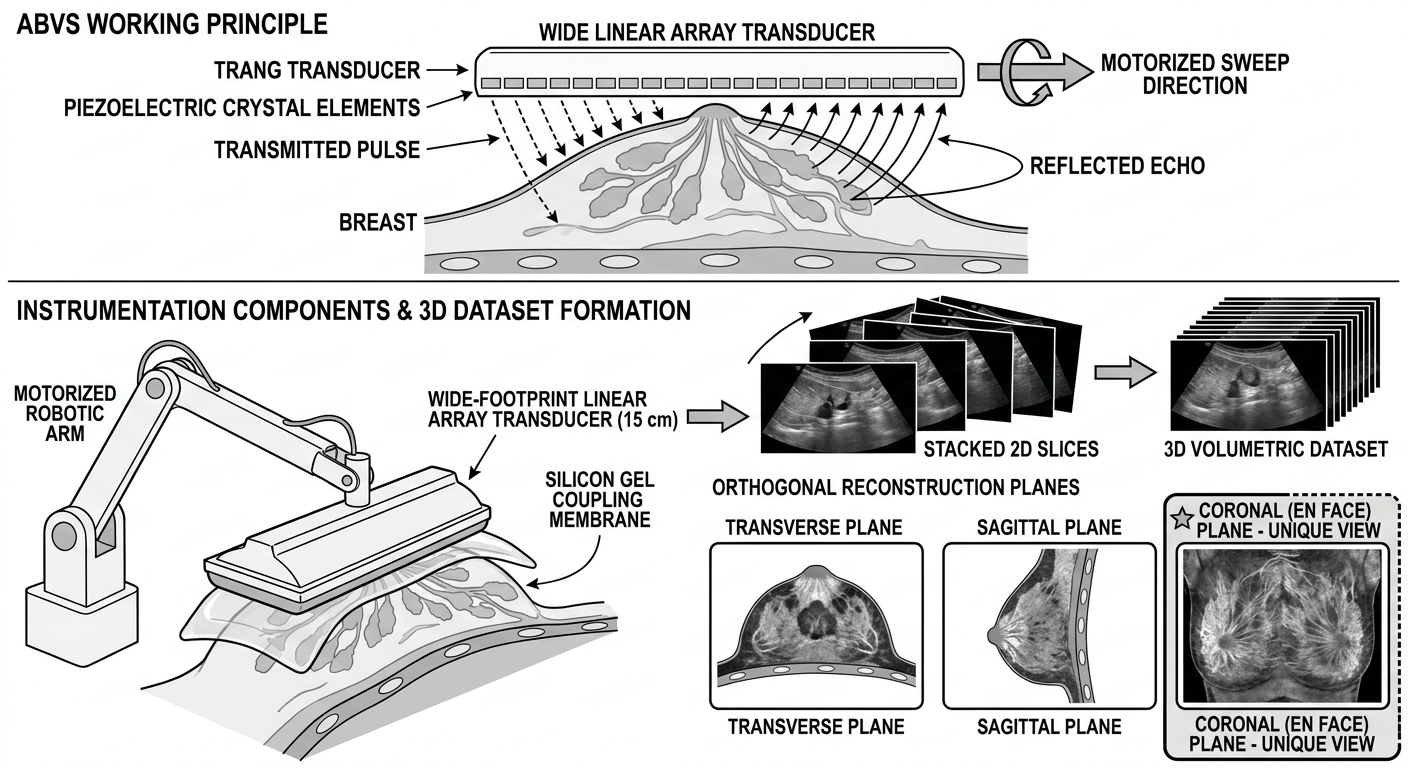
7. MODES OF DISPLAY (Multiplanar Reconstruction — MPR)
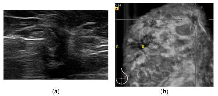
A. Transverse (Axial) Plane
- Standard 2D cross-sectional view (equivalent to HHUS B-mode)
- Shows lesion shape, echogenicity, margins in the horizontal plane
- Familiar to sonographers accustomed to HHUS
B. Sagittal Plane
- Vertical cross-section from superior to inferior
- Complements the transverse plane for lesion characterization
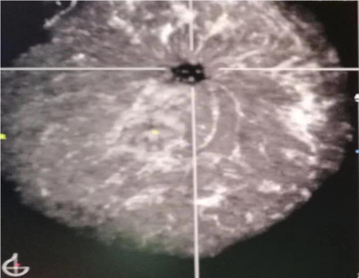
C. Coronal Plane ⭐ (UNIQUE to ABVS — Most Important)
- En face view of the breast from front to back
- Cannot be obtained by HHUS
- Shows the entire breast parenchymal architecture in one plane
- Allows visualization of lesion relationship to entire breast and chest wall
- Shows Cooper's ligaments converging toward the nipple ("convergence sign")
Key Coronal Plane Signs:
| Sign | Description | Significance |
|---|---|---|
| Retraction phenomenon / Sunburst sign | Spiculations radiating outward from a central hypoehoic mass, pulling Cooper's ligaments inward | Highly specific for malignancy |
| Convergence sign | Normal radiating pattern of Cooper's ligaments converging toward the nipple | Normal finding |
| White-wall sign | Hyperechoic rim in the coronal plane corresponding to posterior acoustic enhancement | Seen in cysts / high-grade carcinoma |
| Nipple shadowing artifact | Dark shadow behind nipple in coronal plane — can mimic architectural distortion | False positive — correlate with HHUS |
D. Volume Rendering / 3D Rendering Mode
- Produces a rendered 3D image of the breast volume
- Useful for surgical planning and lesion localization
- Less used in routine diagnosis
8. ANALYSIS — LESION CHARACTERIZATION
BI-RADS Descriptors Used with ABVS
Key Sonographic Features Assessed
Shape
- Oval / Round → Benign
- Irregular → Suspicious
Margins
- Circumscribed → Benign
- Spiculated / Angular / Microlobulated → Malignant
- Spiculated + stellate margin in coronal plane → High specificity for malignancy (Wang et al., 2012)
Orientation
- Parallel (wider-than-tall) → Benign
- Non-parallel (taller-than-wide) → Suspicious
Echogenicity
- Hyperechoic → Benign (lipoma, fat necrosis)
- Hypoechoic → Requires evaluation
- Anechoic → Cyst (if with posterior enhancement)
- Complex / Heterogeneous → Worrisome
Posterior Acoustic Features
- Enhancement → Cysts, high-grade tumors
- Shadowing → Fibrosis, malignancy
- No change → Indeterminate
Coronal Plane Specific Analysis
- Presence/absence of retraction phenomenon — single most important ABVS-specific feature
- Assessment of architectural distortion in the en face view
- Relationship of lesion to nipple, skin, chest wall
Measurement
- ABVS allows 3D volumetric measurement of lesion in all three planes simultaneously
- More accurate than 2D HHUS for preoperative extent assessment (Tozaki & Fukuma, 2010)
9. COMPARISON: ABVS vs. HAND-HELD ULTRASOUND (HHUS)
| Feature | ABVS | HHUS |
|---|---|---|
| Operator dependency | Low (automated) | High (operator-dependent) |
| Reproducibility | High | Variable |
| Coronal plane imaging | Yes (unique) | No |
| 3D volumetric data | Yes | No (unless special probes) |
| Scan time | ~15 min/breast | ~10 min/breast |
| Real-time imaging | No | Yes |
| Spatial resolution (small lesions) | Slightly lower than HHUS | Slightly higher |
| Lesion characterization | Good | Slightly better (real-time) |
| Reproducibility for follow-up | Excellent | Poor |
| Sensitivity (vs mammography) | Higher (similar to HHUS) | Similar to ABVS |
| Patient comfort | Good (prone) | Good (supine) |
| Cost | Higher | Lower |
Wang et al. (2012): Detection rate and diagnostic accuracy were similar between ABVS and HHUS, but both were significantly superior to mammography in dense breasts.
10. PERFORMANCE METRICS (Evidence-Based)
| Metric | Value (95% CI) |
|---|---|
| Sensitivity | 92% (89.9–93.8%) |
| Specificity | 84.9% (82.4–87.0%) |
| Positive Likelihood Ratio | 6.17 (4.36–8.73) |
| Negative Likelihood Ratio | 0.101 (0.075–0.136) |
| Diagnostic Odds Ratio | 72.2 (39.6–131.6) |
11. ADVANTAGES OF ABVS
- Operator independence — results are not dependent on sonographer skill/experience
- Standardized, reproducible images — ideal for serial monitoring
- Coronal plane — unique en face visualization unavailable with HHUS
- 3D volumetric assessment — accurate lesion size/extent measurement
- Complete breast coverage — standardized full-volume acquisition
- No ionizing radiation — safer than mammography/CT for repeated use
- Shorter per-patient time than HHUS for screening large populations
- Better documentation — complete archived volume for retrospective review
- Surgical planning — coronal view aids localization relative to Cooper's ligaments, chest wall
- Telemedicine compatibility — stored volumes can be read remotely
12. LIMITATIONS / DISADVANTAGES
- No real-time imaging — cannot perform dynamic maneuvers (compression, color Doppler during scan)
- No Doppler during acquisition — vascular information not captured in automated sweep
- Nipple shadowing artifact in coronal plane — can mimic architectural distortion (false positive)
- Acoustic shadowing from ribs/chest wall — limits posterior visualization
- Learning curve for coronal plane interpretation — radiologists unfamiliar with en face view
- High initial cost of equipment and workstation
- Longer reading time — large volumetric datasets take more time to review
- Not real-time — cannot guide biopsies directly (biopsy still requires HHUS)
- Positioning challenges for patients unable to lie prone
- Limited axillary coverage — tail of Spence may need additional scan position
- Inter-rater reliability — published studies show heterogeneous quality; more standardization needed
13. ARTIFACTS IN ABVS
| Artifact | Cause | Appearance | Significance |
|---|---|---|---|
| Nipple shadow | Acoustic shadowing from nipple | Dark vertical band on coronal view | Common false positive |
| Rib shadow | Acoustic block from ribs | Dark bands posteriorly | Limits deep tissue evaluation |
| Coupling artifact | Air trapped under membrane | Echo-poor area at skin surface | Technique error — rescan |
| Motion artifact | Patient movement during acquisition | Blurring of image planes | Repeat acquisition needed |
| Reverberation | Skin/membrane interfaces | Parallel bright lines near surface | Near-field artifact |
14. CLINICAL APPLICATIONS
A. Breast Cancer Screening
- Primary role: Supplemental screening in dense breasts (BI-RADS C/D)
- Detects mammographically occult cancers — especially in dense glandular tissue
- Particularly valuable for invasive lobular carcinoma (ILC) — which is notoriously difficult to detect on mammography
B. Lesion Characterization
- Distinguishes benign vs malignant based on BI-RADS descriptors
- Retraction phenomenon in coronal plane → highly specific for malignancy
- Cysts: white-wall sign in coronal plane
C. Preoperative Staging
- Accurate 3D measurement of tumor extent
- Assessment of multifocality/multicentricity
- Tumor-to-nipple distance measurement for surgical planning
D. Neoadjuvant Chemotherapy Monitoring
- Serial volumetric measurements for treatment response assessment
- Standardized, reproducible follow-up scans
E. Post-Treatment Surveillance
- Follow-up after BCS and radiation
- Detecting local recurrence
F. High-Risk Screening
- Complementary to MRI in BRCA mutation carriers
- Alternative when MRI is contraindicated (pacemaker, claustrophobia)
G. Novel Applications
- Soft tissue tumors outside the breast (Chen et al., 2015)
- Photoacoustic hybrid ABVS (PAUS-ABVS) — experimental, combining optical and acoustic imaging for functional information
15. REPORTING SYSTEM — BI-RADS INTEGRATION
| BI-RADS Category | Assessment | Management |
|---|---|---|
| 0 | Incomplete | Additional imaging |
| 1 | Negative | Routine screening |
| 2 | Benign | Routine screening |
| 3 | Probably benign | Short-interval follow-up (6 months) |
| 4 | Suspicious | Tissue sampling (biopsy) |
| 5 | Highly suggestive of malignancy | Biopsy |
| 6 | Known malignancy | Treatment planning |
16. IMAGES
17. KEY EXAM POINTS TO REMEMBER
Mnemonic — ABVS = "A Beautiful View of the breast in 3D Space"
- ABVS uses a 15 cm wide-footprint transducer at 5–14 MHz
- Patient positioned prone (hanging breast through aperture)
- 3 scan positions per breast = complete coverage
- Coronal plane = unique feature, not available with HHUS
- Retraction phenomenon / Sunburst sign on coronal = specific for malignancy
- Nipple shadow = most common false positive artifact in coronal plane
- Meta-analysis sensitivity = 92%, specificity = 84.9%
- No real-time imaging — cannot guide biopsy directly
- FDA cleared 2012 for supplemental screening in dense breasts
- Combined with mammography + HHUS: accuracy reaches 96.4%
- BI-RADS classification applies as with conventional ultrasound
- Major advantage: operator independence and reproducibility
What is the principle and instrumentation of ABVS in detail and give me diagram to draw on notebook for principle or for else
automated breast volume scanner ABVS instrumentation transducer diagram
piezoelectric ultrasound transducer pulse echo principle diagram
A clean, labeled scientific diagram for a medical textbook showing the principle and instrumentation of Automated Breast Volume Scanner (ABVS). The diagram should show: (1) Top section - ABVS working principle: a wide linear array transducer emitting ultrasound pulses into breast tissue, showing pulse-echo principle with labeled arrows showing "Transmitted Pulse", "Reflected Echo", piezoelectric crystal elements, and the motorized sweep direction across the breast. (2) Middle section - Instrumentation components labeled: Motorized Robotic Arm, Wide-Footprint Linear Array Transducer (15 cm), Silicon Gel Coupling Membrane, 3D Volumetric Dataset formation showing stacked 2D slices building into a 3D volume. (3) Bottom section - Three orthogonal reconstruction planes: Transverse, Sagittal, and Coronal (en face) planes shown as three separate boxes with the coronal plane highlighted as unique/special. All labels should be clear, black text on white background, clean educational style, no color shading except subtle gray for anatomy, suitable for drawing in a notebook.
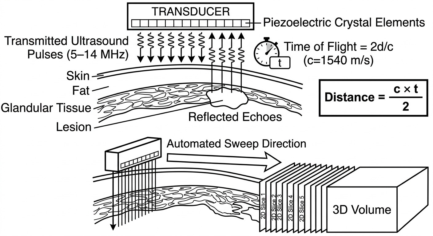
Simple clean black-and-white diagram for a student notebook showing ABVS pulse-echo principle. Show: A rectangular transducer at the top with small rectangles inside representing piezoelectric crystal elements. From the transducer, draw downward arrows labeled "Transmitted Ultrasound Pulses (5-14 MHz)". Below the transducer show breast tissue layers (skin, fat, glandular tissue, lesion). From the lesion draw upward arrows back to the transducer labeled "Reflected Echoes". Add a small clock/timer symbol with label "Time of Flight = 2d/c (c=1540 m/s)". On the right side show a simple equation box: Distance = (c × t) / 2. Below, show the motorized sweep: transducer moving sideways over breast surface with arrow showing "Automated Sweep Direction" and multiple parallel scan lines going down, building up to show "2D Slice 1, Slice 2, Slice 3... → 3D Volume". Clean educational line-art style, black on white, large readable labels.
ABVS — PRINCIPLE AND INSTRUMENTATION
Detailed Exam Notes with Diagrams
PART 1: PRINCIPLE OF ABVS
A. Fundamental Physical Basis — Pulse-Echo Principle
Core Law: Sound waves travel through tissue, reflect at acoustic interfaces, and return to the transducer. The depth of the reflector is calculated from the time taken for the echo to return.
The Pulse-Echo Cycle (Step by Step):
- The piezoelectric crystals in the transducer receive a brief electrical impulse
- They vibrate and emit a short burst (pulse) of ultrasound waves at 5–14 MHz into breast tissue
- The pulse travels through breast tissue at approximately 1540 m/s (speed of sound in soft tissue)
- Wherever there is a change in acoustic impedance (Z = ρ × c, where ρ = density, c = speed of sound), part of the sound energy is reflected back as an echo
- Different tissue interfaces (skin–fat, fat–glandular, normal–lesion) produce echoes of varying amplitude
- Dense or solid tissues reflect more strongly → appear hyperechoic (bright)
- Fluid-filled structures reflect less → appear hypoechoic/anechoic (dark)
- The same piezoelectric crystals now act as receivers (alternating transmit/receive mode)
- Incoming echoes cause the crystals to vibrate → generate electrical signals proportional to echo amplitude
- d = depth of reflector (cm)
- c = speed of sound = 1540 m/s
- t = time elapsed between pulse and echo return
- Divided by 2 because the sound travels to the reflector AND back
- The amplitude of each echo is converted to brightness (B = Brightness)
- The position is mapped spatially using the depth (time-of-flight) and transducer element position
- Hundreds of scan lines side-by-side build up a single 2D B-mode image slice
B. What Makes ABVS Different From Conventional HHUS — The 3D Volumetric Principle
| Feature | HHUS | ABVS |
|---|---|---|
| Scanning | Manual, freehand | Automated, motorized |
| Output | Single 2D frames in real time | Full 3D volumetric dataset |
| Planes | Transverse + Sagittal only | Transverse + Sagittal + CORONAL |
| Operator influence | High | Minimal |
How 3D Volume is Built:
- The wide-footprint transducer (15 cm) acquires a 2D B-mode image at Position 1
- The motorized arm moves the transducer a fixed, precise distance (step increment)
- Another 2D slice is acquired at Position 2
- This continues automatically across the entire breast surface
- Hundreds of parallel 2D slices, acquired at known intervals, are stacked together computationally to form a 3D volumetric dataset
- The workstation then uses Multiplanar Reconstruction (MPR) to reconstruct any desired plane from this volume — including the unique coronal (en face) plane
C. The Coronal Plane — The Defining Principle of ABVS
- Not possible with HHUS (2D transducer cannot acquire this plane)
- Requires a full 3D volumetric dataset reconstructed computationally
- Shows Cooper's ligaments, parenchymal architecture, and tumor relationships in the en face view
- The retraction phenomenon / sunburst sign — visible only on the coronal plane — is highly specific for malignancy
Diagram 1: ABVS Pulse-Echo Principle + Automated Sweep → 3D Volume
- Draw a rectangular transducer at top with small boxes inside = piezoelectric elements
- Draw zigzag arrows going DOWN = transmitted pulses (label: 5–14 MHz)
- Draw layers below: Skin / Fat / Glandular Tissue / Lesion
- Draw arrows going UP from lesion back to transducer = reflected echoes
- Write the formula box: d = (c × t) / 2, c = 1540 m/s
- Below: draw transducer moving sideways → generating parallel vertical lines into tissue → these build up into stacked "2D Slice 1, 2, 3..." → arrow → "3D Volume" box
Diagram 2: Full ABVS System Diagram — Principle + Instrumentation + Planes
PART 2: INSTRUMENTATION IN DETAIL
Overview of ABVS System Components
┌─────────────────────────────────────────────────┐
│ ABVS SYSTEM COMPONENTS │
│ 1. Wide-Footprint Linear Array Transducer │
│ 2. Motorized Robotic Arm │
│ 3. Gel-Filled Silicon Coupling Membrane │
│ 4. Touchscreen Control Unit │
│ 5. 3D Workstation (Post-Processing) │
└─────────────────────────────────────────────────┘
Component 1: Wide-Footprint Linear Array Transducer ⭐
| Parameter | Specification |
|---|---|
| Type | Linear array (not curved/convex) |
| Footprint width | ~15 cm (vs 3–5 cm in HHUS) |
| Frequency range | 5–14 MHz (broadband) |
| Number of elements | Hundreds of piezoelectric crystals |
| Orientation | Wide, flat face for broad surface coverage |
How It Works:
- Contains hundreds of piezoelectric elements arranged side by side in a linear row
- Each element can independently transmit and receive ultrasound pulses
- Elements fire in rapid sequence (electronic focusing) to build a 2D B-mode image
- The 15 cm footprint means each single sweep captures a wide tissue area — far more than HHUS
- Broadband (5–14 MHz): lower frequencies penetrate deeper; higher frequencies give better resolution of superficial lesions. The system automatically optimizes based on depth
Piezoelectric Effect (Core Physics):
- Direct piezoelectric effect: mechanical pressure → electrical signal (reception of echoes)
- Reverse piezoelectric effect: electrical signal → mechanical vibration (transmission of pulses)
- Material: usually PZT (Lead Zirconate Titanate) crystals
- Each element is electrically pulsed for ~1 microsecond → sends out a short pulse → then switches to receive mode
Component 2: Motorized Robotic Arm
| Feature | Detail |
|---|---|
| Function | Holds and moves the transducer in a controlled, automated sweep |
| Movement | Precisely controlled motor drives transducer across the breast |
| Speed | Constant, controlled velocity (eliminates speed-dependent artifacts) |
| Positioning | Flexible arm adjusts to breast contour and patient anatomy |
| Degree of freedom | Rotational + translational movement |
- The arm ensures uniform pressure across the entire breast surface
- Prevents the operator variability inherent in HHUS (different sonographers apply different angles/pressures)
- The transducer position is continuously tracked by the system, which maps each 2D slice to its exact spatial location in the 3D volume
Component 3: Gel-Filled Silicon Coupling Membrane (Acoustic Coupling Pad)
| Feature | Detail |
|---|---|
| Material | Soft, flexible silicone membrane |
| Filling | Aqueous gel or saline |
| Purpose | Eliminate air gaps between transducer and breast skin |
| Benefit | Conforms to uneven breast surface; ensures uniform acoustic coupling |
| Stand-off | Provides controlled stand-off distance (allows near-field imaging) |
- Without the membrane: air between transducer and skin would reflect virtually all ultrasound (acoustic impedance mismatch) — no image possible
- With the membrane: smooth acoustic coupling across the entire 15 cm footprint
- The membrane also protects the transducer from direct skin contact and contamination
Component 4: Touchscreen Control Unit
| Function | Detail |
|---|---|
| Patient data entry | ID, age, exam date, laterality |
| Breast size selection | Small / Medium / Large / XL presets |
| Scan position selection | Anterior / Lateral / Medial positions |
| Parameter adjustment | Gain, depth, focus zones (auto-optimized) |
| Real-time monitoring | Displays acquisition progress |
| Nipple marker | Operator marks nipple position as anatomical reference |
- Presets automatically configure: scan depth, time-gain compensation, focus zones, and compression based on breast size
- The nipple marker is critical for post-processing MPR alignment — it anchors the coronal plane reconstruction
Component 5: 3D Workstation (Post-Processing & Display Unit)
Functions:
- Volumetric reconstruction: stacks all 2D slices into a seamless 3D dataset
- Multiplanar Reconstruction (MPR): generates transverse, sagittal, and coronal planes
- Scrolling: radiologist scrolls through each plane slice by slice
- 3D rendering: surface or volume rendering for surgical planning
- Measurement tools: 3D lesion size measurement in all three planes simultaneously
- PACS integration: stores and transmits studies
- BI-RADS reporting template: integrated reporting tools
Display Layout on Workstation:
┌──────────────┬──────────────┐
│ TRANSVERSE │ SAGITTAL │
│ (axial) │ (vertical) │
├──────────────┼──────────────┤
│ CORONAL │ 3D RENDER │
│ (en face) │ / INFO │
└──────────────┴──────────────┘
Quad-view MPR display
Summary Flowchart: ABVS — From Patient to Diagnosis
PATIENT (prone position, breast hanging through aperture)
↓
COUPLING MEMBRANE applied to breast surface
↓
TRANSDUCER (15 cm, 5–14 MHz) activated
↓
PIEZOELECTRIC CRYSTALS fire ultrasound pulses (5–14 MHz)
↓
PULSES penetrate breast tissue → reflect at acoustic interfaces
↓
ECHOES return → d = (c × t) / 2
↓
MOTORIZED ARM sweeps transducer → 2D Slice 1 → 2 → 3 → ... (hundreds)
↓
3D VOLUMETRIC DATASET assembled in workstation
↓
MPR RECONSTRUCTION: Transverse + Sagittal + CORONAL planes
↓
RADIOLOGIST reviews → BI-RADS classification → DIAGNOSIS
Key Exam Points for Principle & Instrumentation
| # | Point |
|---|---|
| 1 | ABVS uses Pulse-Echo Principle — d = (c × t) / 2, c = 1540 m/s |
| 2 | Piezoelectric crystals — dual role: transmit (reverse effect) + receive (direct effect) |
| 3 | Transducer frequency: 5–14 MHz (broadband linear array) |
| 4 | Transducer footprint: 15 cm (vs 3–5 cm for HHUS) |
| 5 | Silicon gel membrane = acoustic coupling; conforms to breast surface |
| 6 | Motorized arm = automated sweep = operator-independent, reproducible |
| 7 | Hundreds of parallel 2D slices → stacked → 3D volumetric dataset |
| 8 | MPR generates 3 planes: Transverse, Sagittal, Coronal (unique) |
| 9 | Coronal plane = en face view — only possible with 3D volumetric data |
| 10 | Retraction phenomenon on coronal = Cooper's ligaments pulled by malignancy |
Give me notes on stitch radiography in detail
stitch radiography long length spine scoliosis digital imaging
panoramic radiography scoliosis whole spine image acquisition technique
EOS imaging full body radiography low dose orthopedic
stitch radiography long cassette spine scoliosis full length
digital radiography image stitching long bone lower limb alignment
full spine standing radiograph scoliosis Cobb angle measurement technique
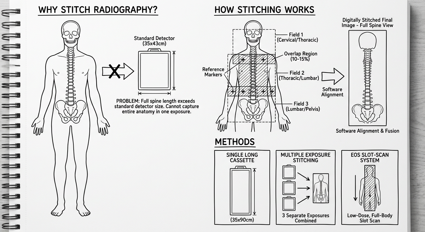
Clean educational black-and-white diagram for a radiology student notebook explaining Stitch Radiography technique. Show three sections: Section 1 (top): "Why Stitch Radiography?" - draw a human outline showing the problem: the full spine from skull to pelvis is too long to fit on a single standard X-ray detector (35x43cm), show the detector being much smaller than the body. Section 2 (middle): "How Stitching Works" - Show the same human outline with 2 or 3 overlapping rectangular X-ray fields labeled Field 1, Field 2, Field 3 with overlapping zones hatched/shaded. Show an arrow pointing right to a composite final image labeled "Digitally Stitched Final Image - Full Spine View". Include labels: "Overlap Region (10-15%)", "Reference Markers", "Software Alignment". Section 3 (bottom): "Methods" - Draw three small boxes side by side: Box 1 labeled "Single Long Cassette (35x90cm)" showing one tall narrow rectangle, Box 2 labeled "Multiple Exposure Stitching" showing 3 small rectangles being combined, Box 3 labeled "EOS Slot-Scan System" showing a slot scanning top to bottom. All in clean line-art style with clear labels, suitable for copying into a notebook.
full length lower limb radiograph standing alignment knee hip ankle stitched
STITCH RADIOGRAPHY
Detailed Exam Notes
1. DEFINITION
The term "stitch" refers to the process of digitally sewing together multiple images at their overlapping borders — analogous to stitching pieces of fabric.
- Long-length radiography
- Full-length radiography
- Teleoroentgenography (historical term for long-leg films)
- Slot-scan radiography (EOS system)
- Whole-spine radiography
- Panoramic radiography
2. HISTORICAL BACKGROUND
| Era | Development |
|---|---|
| 1930s–1950s | "Teleoroentgenography" — long-cassette (90 cm) radiographs used for leg length discrepancy assessment; patient moved between exposures |
| 1960s–1970s | Long flexible cassette systems; single-exposure 90 cm films using large-format screens |
| 1980s–1990s | Computed radiography (CR) with image plates allowing digital storage; early digital stitching attempts |
| 2000s | Digital Radiography (DR) flat-panel detectors; software-based automatic image stitching emerges |
| 2007 | EOS imaging system introduced (Nobel Prize–related technology by Georges Charpak) — slot-scan low-dose full-body imaging |
| 2010s–present | Automated stitch radiography becomes standard; AI-assisted alignment algorithms; weight-bearing 3D reconstruction (stereoradiography) |
- The full spine (cervical to sacrum = ~60–70 cm)
- Full lower limbs from hip to ankle (~90–100 cm)
- Full upper limb
3. PRINCIPLE OF STITCH RADIOGRAPHY
Core Concept:
Step-by-Step Process:
STEP 1: Patient positioned → does NOT move throughout entire examination
↓
STEP 2: First X-ray field captured (e.g., cervical + upper thoracic spine)
↓
STEP 3: X-ray tube/detector shifts to next position (patient stationary)
↓
STEP 4: Second X-ray field captured — with deliberate overlap of ~10–15%
↓
STEP 5: Repeat for 3rd field if needed (e.g., lumbar + pelvis)
↓
STEP 6: Dedicated software identifies common anatomical landmarks in overlap zones
↓
STEP 7: Software aligns and blends all fields → seamless composite image
↓
FINAL: Single long-format image on workstation/PACS for measurement
The Overlap Zone — Critical Principle:
- Each adjacent field must overlap by 10–15% (approximately 4–6 cm)
- The overlap region contains identical anatomy visible in both images
- Software uses this shared anatomy as registration/reference points to align the two fields precisely
- Poor overlap → misalignment ("stitching artifact") → distorted measurements
Key Physical Principle — Geometric Magnification Control:
- The X-ray tube is kept at a standardized focus-to-detector distance (FDD) — usually 150–180 cm
- Longer FDD reduces geometric magnification distortion
- Same FDD for all exposures ensures consistent magnification factor across all fields
- A calibration marker (metal ball of known diameter) is placed at the level of the hips to calculate the exact magnification factor for length measurements
Diagram for Notebook:
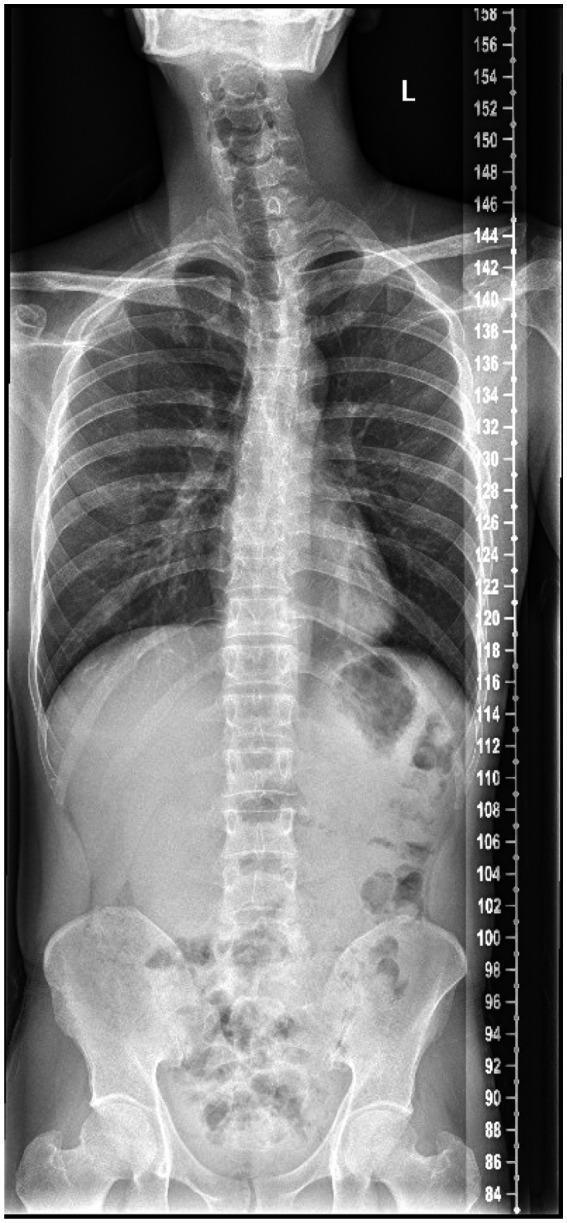
4. INDICATIONS
A. Spinal Indications (Most Common)
- Scoliosis — measurement and monitoring of Cobb angle (most important indication)
- Kyphosis — measurement of thoracic kyphosis angle
- Spondylolisthesis — full spinal alignment assessment
- Spinal deformity pre/post surgery — evaluation of correction achieved
- Spinal fusion surgery planning — assessment of global spinal balance
- Sagittal imbalance assessment — SVA (Sagittal Vertical Axis) measurement
- Degenerative disc disease — overall spinal alignment
- Congenital spine deformity — monitoring in children
B. Lower Limb Indications
- Leg length discrepancy (LLD) — accurate measurement of femoral and tibial lengths
- Lower limb alignment — Hip-Knee-Ankle (HKA) mechanical axis assessment
- Varus/valgus deformity — genu varum (bow legs) / genu valgum (knock knees)
- Pre-operative planning for Total Knee Arthroplasty (TKA) — mechanical axis calculation
- High tibial osteotomy (HTO) planning — correction angle calculation
- Post-operative assessment — alignment after osteotomy or joint replacement
- Perthes disease / DDH — lower limb development monitoring
C. Other Indications
- Full-body weight-bearing assessment — global posture and alignment
- Limb lengthening (Ilizarov/fixator) — monitoring lengthening progress
- Soft tissue sarcoma — extent of long bone involvement
- Skeletal dysplasias — full-body skeletal survey
5. METHODS / TECHNIQUES OF STITCH RADIOGRAPHY
Method 1: Single Long Cassette (Conventional Method)
| Feature | Detail |
|---|---|
| Cassette size | 35 × 90 cm (special long-format cassette) |
| Film/detector | Long CR image plate or single long DR detector |
| Exposures | Single exposure covering entire length |
| Patient position | Standing (weight-bearing) |
| Advantage | True single-exposure — no stitching required; no alignment error |
| Disadvantage | Non-uniform exposure across length; center of beam optimal, periphery overexposed/underexposed; radiation dose higher; less flexible |
| Use | Spine surveys, limb length |
Method 2: Multiple Exposure Digital Stitching ⭐ (Most Common Modern Method)
| Feature | Detail |
|---|---|
| Detector | Standard flat-panel DR detector (35×43 cm) |
| Number of exposures | 2–4 exposures (depending on body part and patient height) |
| Overlap | 10–15% overlap between adjacent fields |
| Patient movement | Patient does NOT move — detector/tube moves |
| Alignment | Automatic software stitching using overlapping anatomy |
| Calibration | Metallic calibration ball placed at hip level |
| Advantage | Uniform exposure for each field; standard detectors used; flexible; digital |
| Disadvantage | Risk of stitching artifacts; patient must remain absolutely still |
| Systems | Most modern DR systems (Siemens, Philips, GE, Carestream) |
Sub-variants:
- Motorized Bucky / Moving Detector: detector moves automatically on a motorized track while tube shifts correspondingly
- Fixed Detector, Moving Tube: only the X-ray tube shifts to the next field position
Method 3: EOS Slot-Scan System (Most Advanced)
| Feature | Detail |
|---|---|
| Principle | Slot-scan radiography using slot detectors |
| Technology | Based on Nobel Prize–winning wire proportional counter (Georges Charpak) |
| Scan | X-ray slit beam + detector scan top-to-bottom simultaneously while patient stands |
| Dose | Ultra-low dose — up to 8× less radiation than conventional radiography |
| Output | PA and lateral full-body images simultaneously (biplanar) |
| 3D capability | Stereoradiography — 3D reconstruction of skeleton from 2 perpendicular views |
| Patient position | Weight-bearing, standing |
| Advantage | True simultaneous biplanar; 3D; lowest dose; no stitching artifacts |
| Disadvantage | High cost; limited availability; longer acquisition time (~20 sec) |
| Indications | Scoliosis, spinal deformity, hip/knee arthroplasty planning |
6. TECHNICAL PARAMETERS
Exposure Factors
| Parameter | Spine | Lower Limb |
|---|---|---|
| kVp | 80–100 kVp | 75–85 kVp |
| mAs | 20–50 mAs per field | 20–40 mAs per field |
| FDD (Focus-Detector Distance) | 150–180 cm | 150–180 cm |
| Collimation | Tightly collimated to field | Tightly collimated |
| Grid | Yes (Bucky grid) | Yes |
| AEC | Used if available | Used if available |
Critical Technical Requirements:
- Patient must be absolutely still between exposures — any movement causes misalignment
- Consistent FDD across all exposures — ensures uniform magnification
- Calibration marker placement — essential for accurate length measurement
- Beam centering — central ray must be perpendicular to detector for each exposure
- Overlap zone — 10–15%, never less than 3 cm
- No rotation — patient position must not change between exposures
7. PATIENT POSITIONING TECHNIQUES
A. Spinal Stitch Radiography
| View | Projection | Position Details |
|---|---|---|
| AP (Posteroanterior — PA preferred) | PA | Patient faces detector; spine parallel to detector; arms slightly forward or folded; chin up |
| Lateral | Lateral | 90° rotation; feet together or slightly apart; arms raised (holding bars or touching shoulders) |
- In PA position, the spine is closer to the detector → less magnification, sharper image
- Reduces radiation dose to radiosensitive anterior structures (thyroid, breast, gonads)
- PA = standard for scoliosis monitoring (Nash-Moe protocol)
- Patient stands straight, weight equally distributed on both feet
- No shoes with heels — bare feet or flat shoes
- Knees extended (full extension)
- For scoliosis: hands resting on supports at shoulder height
- Reference markers placed on posterior superior iliac spine (PSIS) or femoral heads
- Average adult: 2 fields (upper: skull/C-spine → T12; lower: T10/L1 → sacrum/pelvis)
- Taller patients: 3 fields (cervical, thoracic, lumbar-pelvis)
- Generous overlap at each junction (~T6–T8 region)
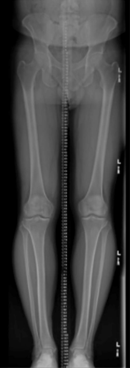
B. Lower Limb Stitch Radiography
| Requirement | Detail |
|---|---|
| Patient position | Standing erect, both feet flat on floor |
| Foot position | Feet together, toes pointing forward (15° internal rotation preferred to show femoral neck best) |
| Patella | Facing directly forward (standardized rotation) |
| Arms | At sides or holding supports |
| Calibration ball | Placed at level of femoral head (fixed to stand between legs) |
- From femoral heads to ankle mortice (some protocols include pelvis to feet)
- Typically 2 exposures: upper (pelvis to mid-tibia) + lower (mid-femur to ankle)
- Overlap at knee level
C. Upper Limb Stitch Radiography
- Less common; used for limb lengthening assessment
- Patient seated or standing; arm fully extended against detector
- AP or lateral view
8. DIGITAL STITCHING PROCESS — SOFTWARE WORKFLOW
Automatic Stitching Algorithm:
- Input: 2–4 separate digital radiographic fields
- Overlap detection: Software identifies the overlapping region in adjacent images
- Feature matching: Identifies matching anatomical landmarks (vertebral endplates, cortical bone edges, disc spaces) in the overlap zone
- Geometric correction: Corrects for any minor parallax distortion or magnification differences
- Image blending: Overlap zone is blended (feathering algorithm) — eliminates visible seam
- Concatenation: Fields joined into a single long-format image
- Output: Single composite image available for measurement tools
Types of Stitching Errors (Artifacts):
| Error | Cause | Appearance | Effect |
|---|---|---|---|
| Step artifact (staircase) | Patient movement between exposures | Visible step at junction | Measurement error |
| Double exposure ghost | Excessive overlap + misalignment | Ghosting/blurring at junction | Anatomy duplicated |
| Magnification mismatch | Different FDD for different fields | Size discrepancy across images | Incorrect length measurement |
| Seam artifact | Under-blending at junction | Visible line across image | Cosmetic but also diagnostic concern |
| Rotation artifact | Patient rotated between shots | Vertebrae appear at different angles at junction | False scoliosis appearance |
9. MEASUREMENTS PERFORMED ON STITCH RADIOGRAPHS
A. Spinal Measurements
| Measurement | Definition | Purpose |
|---|---|---|
| Cobb Angle | Angle between endplates of most tilted vertebrae above and below the curve | Scoliosis severity; monitoring |
| Sagittal Vertical Axis (SVA) | Horizontal distance from C7 plumb line to posterior sacrum | Global sagittal balance |
| Coronal Balance | Distance from C7 plumb line to central sacral vertical line | Coronal alignment |
| Thoracic Kyphosis | T2–T12 Cobb angle | Kyphosis assessment |
| Lumbar Lordosis | L1–S1 Cobb angle | Lordosis assessment |
| Pelvic Incidence (PI) | Fixed morphological angle (sacral endplate to hip axis) | Spinopelvic parameters |
| Pelvic Tilt (PT) | Dynamic parameter | Pelvic compensation |
| Sacral Slope (SS) | Angle of S1 endplate to horizontal | Pelvic orientation |
B. Lower Limb Measurements
| Measurement | Definition | Purpose |
|---|---|---|
| True leg length | Femoral head center to ankle mortice (corrected for magnification) | LLD assessment |
| Femoral length | Femoral head center to knee joint center | Individual bone length |
| Tibial length | Knee joint center to ankle center | Individual bone length |
| Hip-Knee-Ankle (HKA) angle | Mechanical axis angle (normal = 179°, i.e., nearly straight) | Varus/valgus deformity |
| Mechanical axis deviation (MAD) | Distance of mechanical axis from knee center | Knee joint load distribution |
| mLDFA | Mechanical Lateral Distal Femoral Angle | Distal femur alignment |
| MPTA | Medial Proximal Tibial Angle | Proximal tibia alignment |
10. CLINICAL APPLICATIONS IN DETAIL
A. Scoliosis Management
- Initial diagnosis: full-spine PA + lateral stitch radiograph
- Monitoring: serial Cobb angle measurement (treatment threshold: >10° = scoliosis; >25° = bracing; >45° = surgery)
- Brace effectiveness: comparing Cobb angle in/out of brace
- Post-surgical evaluation: instrumented correction assessment
B. Preoperative TKA Planning
- Full lower limb stitch required for:
- Measuring mechanical axis (Hip-Knee-Ankle angle)
- Planning component alignment to restore neutral mechanical axis
- Calculating required tibial/femoral resection angles
- Without correct mechanical axis data → TKA component malalignment → early failure
C. High Tibial Osteotomy (HTO)
- Required to determine varus correction angle
- Calculates Fujisawa point (target for weight-bearing line post-correction)
- Post-operative: verifies achieved correction
D. Limb Length Discrepancy
- Scanogram (orthoroentgenogram): 3 separate exposures — hip, knee, ankle with ruler
- Modern stitch replaces traditional scanogram
- Determines which bone is short (femur vs tibia) and by how much
E. Spinal Surgery Planning (Adult Deformity)
- EOS / stitch radiograph provides spinopelvic parameters
- Global sagittal alignment (PI-LL mismatch)
- Helps surgeon select levels for fusion and required lordosis correction
11. RADIATION DOSE CONSIDERATIONS
| Method | Effective Dose | Comparison |
|---|---|---|
| Single long cassette (35×90 cm) | ~1.0–2.0 mSv | Higher — non-optimized per field |
| Multiple exposure digital stitch | ~0.5–1.5 mSv (spine) | Similar to conventional |
| EOS biplanar | ~0.05–0.1 mSv (full body) | 8–10× less than conventional |
| CT spine | ~5–8 mSv | Much higher |
- PA (not AP) projection for spine — reduces breast/thyroid dose
- Tight collimation
- AEC (automatic exposure control)
- EOS system for children and repeated monitoring (scoliosis)
Note: In scoliosis patients who require serial monitoring over years, dose reduction is critically important — especially for young females at risk for breast radiation. EOS is preferred.
12. ADVANTAGES OF STITCH RADIOGRAPHY
- Comprehensive anatomical coverage in a single composite view — whole spine or full limb
- Weight-bearing images — physiological loading position (gravity effect on alignment)
- Accurate global measurements — Cobb angle, mechanical axis, leg length
- Surgical planning — cannot be replaced by non-weight-bearing MRI/CT for alignment
- Serial monitoring — standardized, reproducible technique
- No special cassette needed (digital stitching uses standard detectors)
- Widely available — standard DR equipment with stitching software
- Non-invasive, fast — ~5 minutes total examination time
13. LIMITATIONS / DISADVANTAGES
- Patient must remain absolutely still — any movement = stitching artifact
- Stitching artifacts — step artifact can mimic or mask scoliosis
- Magnification — must be corrected with calibration ball; errors in length if calibration omitted
- Parallax distortion — lateral edges of each field have geometric distortion
- Radiation dose — higher than single-field imaging; concern in pediatric scoliosis
- Not real-time — cannot assess dynamic instability
- Overlying soft tissue/bowel gas — can obscure spinal detail in abdominal region
- Positioning errors — rotation of patient between shots = false measurement
- Cost of specialized software — auto-stitching requires dedicated workstation/software
14. COMPARISON: STITCH RADIOGRAPHY vs EOS vs CT
| Feature | Stitch Radiography | EOS | CT |
|---|---|---|---|
| Radiation dose | Moderate | Very low | High |
| Weight-bearing | Yes | Yes | No (supine) |
| Full-length imaging | Yes | Yes | Partial (scanner length) |
| 3D reconstruction | No | Yes (stereo) | Yes |
| Cost | Low–Moderate | High | Moderate–High |
| Availability | Widely available | Limited | Available |
| Stitching artifacts | Yes | None (slot scan) | None |
| Dynamic imaging | No | No | No |
15. IMAGES
16. KEY EXAM POINTS TO REMEMBER
| # | High-Yield Point |
|---|---|
| 1 | Stitch = multiple overlapping exposures digitally merged into one long composite image |
| 2 | Overlap zone = 10–15% — critical for alignment |
| 3 | Patient must NOT move between exposures |
| 4 | FDD = 150–180 cm — standardized for all fields to maintain consistent magnification |
| 5 | Calibration marker (metal ball at hip) = mandatory for accurate length measurement |
| 6 | PA preferred over AP for spine — less radiation to breast/thyroid |
| 7 | Most common indication: scoliosis (Cobb angle) and lower limb alignment (HKA axis) |
| 8 | EOS = slot-scan, lowest dose (~8× less), simultaneous biplanar, can 3D reconstruct |
| 9 | Most common artifact: step artifact from patient movement |
| 10 | Standard detector size: 35×43 cm; special long cassette: 35×90 cm |
| 11 | Weight-bearing position = physiological = mandatory for alignment measurements |
| 12 | TKA planning requires full-limb stitch to measure mechanical axis (HKA angle) |