I now have all the material needed. Let me compile the comprehensive MD exam-style answer.
Vaporizers in Anaesthesia - Classification and Types
Sources: Miller's Anesthesia 10e (Ch. 20) | Barash Clinical Anesthesia 9e (Ch. 25)
PHYSICAL PRINCIPLES UNDERPINNING VAPORIZER DESIGN
Before classifying vaporizers, the following physical principles govern their design and function:
Saturated Vapour Pressure (SVP)
- The pressure exerted by vapour molecules in equilibrium with the liquid phase at a given temperature
- SVP is temperature-dependent (increases with temperature) but independent of atmospheric pressure
- SVP of common agents at 20°C: Desflurane ~669 mmHg, Sevoflurane ~160 mmHg, Isoflurane ~240 mmHg, Halothane ~243 mmHg
Latent Heat of Vaporization
- Energy required to convert liquid to gas; absorbed from surroundings causing evaporative cooling
- As liquid evaporates, remaining liquid cools -> SVP falls -> vaporizer output decreases
- Modern vaporizers compensate for this via materials of high specific heat and thermal conductivity
Boiling Point
- Temperature at which SVP equals atmospheric pressure; inversely related to volatility
- Desflurane boiling point = 22.8°C at 1 atm - dangerously close to room temperature; explains why it needs a special vaporizer
Thermal Conductivity and Specific Heat
- Vaporizers are made of metals with high thermal conductivity (to maintain uniform temperature) and high specific heat (to minimize temperature swings during vaporization)
CLASSIFICATION OF VAPORIZERS
Classification Scheme (Exam-Oriented Summary)
| Criterion | Types |
|---|
| Position relative to circuit | In-circuit (draw-over) vs. Out-of-circuit (plenum) |
| Method of vaporization | Flow-over vs. Bubble-through (measured flow) |
| Temperature compensation | Temperature-compensated vs. Not compensated |
| Agent specificity | Agent-specific vs. Multi-agent |
| Control mechanism | Variable bypass / Dual-circuit / Cassette / Injection |
MODERN VAPORIZER TYPES (Miller's Anesthesia 10e, p.2278)
Vaporizers are first designated as in-circuit or out-of-circuit, then by specific type. All modern vaporizers fall into four major types:
- Variable bypass vaporizer
- Dual-circuit vaporizer (Tec 6-style, for desflurane)
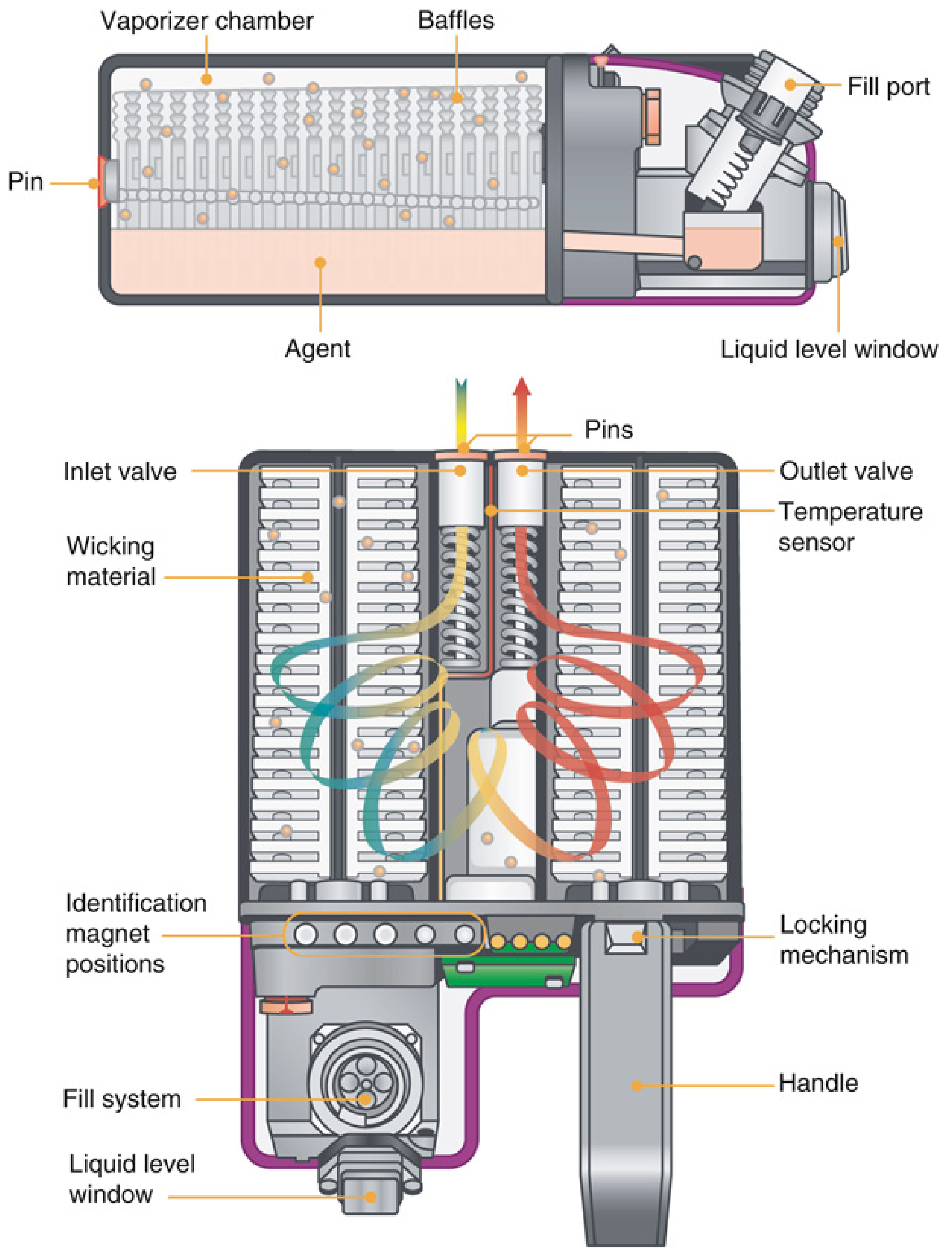
- Cassette vaporizer (Aladin/Aladin2)
- Injection vaporizer (Maquet DIVA/Dräger DIVA)
TYPE 1: VARIABLE BYPASS VAPORIZER
Classification
- Variable bypass, flow-over, temperature-compensated, agent-specific, out-of-circuit
- Examples: GE Tec 5, Tec 7, 850; Dräger Vapor 2000, Vapor 3000
Principle of Operation
Fresh gas from flowmeters enters the vaporizer inlet. The concentration control dial determines the splitting ratio - the fraction of gas diverted to the vaporizing chamber vs. the bypass chamber.
- Gas through the bypass chamber carries no anesthetic
- Gas through the vaporizing chamber flows over wicks saturated with liquid anesthetic and becomes fully (or partially) saturated with vapour
- These two streams recombine at the vaporizer outlet to produce the desired output concentration
Splitting ratio = bypass flow / vaporizing chamber flow; agent-specific and dial-dependent
| Agent | Approximate Splitting Ratio at 20°C, 2% dial |
|---|
| Halothane | ~4.5:1 |
| Isoflurane | ~45:1 |
| Sevoflurane | ~13:1 |
| Desflurane | Cannot be used - explained below |
Temperature Compensation
Because SVP falls as the liquid cools (latent heat effect), a bimetallic strip or bellows mechanism automatically adjusts the splitting ratio to maintain constant output across a range of operating temperatures (typically 15-35°C).
Key Features
- Flow-over (not bubble-through) - gas passes over the wick surface
- Wicks and baffles increase surface area for evaporation and promote mixing
- Agent-specific filling systems (colour-coded, pin-indexed) prevent misfilling
- Interlock systems prevent simultaneous use of two vaporizers
- Calibrated at sea level (760 mmHg)
Effect of Altitude (Variable Bypass)
At altitude, barometric pressure falls but SVP remains constant:
- Volume percent output increases (more anesthetic molecules per unit volume)
- Partial pressure output changes minimally (only slightly decreases)
- Because anesthetic depth is determined by partial pressure in brain, no dial adjustment is needed - a clinically important fact
Effect of Carrier Gas Composition
- If N2O replaces O2 as carrier gas, N2O (being more soluble in liquid agent) initially increases output then decreases it
- With halothane: initial brief rise in output, then fall to a lower steady state
TYPE 2: DUAL-CIRCUIT VAPORIZER (DESFLURANE - Tec 6 and D-Vapor)
Why Desflurane Cannot Use a Variable Bypass Vaporizer
Three reasons (frequently asked in exams):
-
Extremely high SVP (669 mmHg at 20°C): At 100 mL/min through the vaporizing chamber, 735 mL/min of desflurane would be entrained, giving 88% desflurane. To dilute to 6% (1 MAC) would require ~12 L/min bypass flow - prohibitively high.
-
Excessive evaporative cooling: Desflurane's MAC is 4-9x higher than other agents. Far more liquid must be vaporized per unit time. Without an external heat source, temperature compensation by mechanical means alone would be impossible.
-
Risk of boiling: Boiling point 22.8°C at 1 atm is within normal OR temperature range. If it boiled inside a variable bypass vaporizer, output would be uncontrollable.
Classification
- Electrically heated, pressurized, dual-circuit, agent-specific, out-of-circuit
- More accurately described as a "dual-gas blender" than a vaporizer
Operating Principle (Tec 6)
The Tec 6 has two independent gas circuits arranged in parallel:
- Fresh gas circuit (darker): FGF from flowmeters → fixed restrictor R1 → vaporizer gas outlet
- Vapor circuit (lighter): Desflurane sump is electrically heated to 39°C (well above its boiling point). At 39°C, SVP ≈ 1,500 mmHg (2 atm absolute), creating a reservoir of desflurane vapour
The shutoff valve opens when the concentration dial is turned ON. A pressure-regulating valve reduces sump pressure to ~1.1 atm absolute (74 mmHg gauge) at 10 L/min FGF.
The operator adjusts output via the concentration control valve R2 (variable restrictor).
The two circuits are physically separated but pneumatically interfaced:
- A differential pressure transducer senses back-pressure from the FGF in R1
- Control electronics adjust the pressure-regulating valve so that pressure in the vapour circuit equals pressure in the fresh gas circuit (equalization = same working pressure for R1 and R2)
- The resulting mixing at the junction of R1 and R2 produces the dialed concentration
Effect of Altitude (Tec 6 - Important Exam Point!)
The Tec 6 maintains a constant volume percent output (not constant partial pressure) because it is a blender that achieves the dialed v/v% regardless of ambient pressure.
- At altitude: Tec 6 delivers the dialed vol%, but partial pressure of desflurane decreases proportionally with reduction in atmospheric pressure
- Contrast with variable bypass vaporizers (where partial pressure is relatively constant)
- Clinical implication: At altitude, a higher dial setting may be needed with the Tec 6
Safety Features
- Agent-specific SAF-T-FILL adapter on desflurane bottles - prevents use in standard variable bypass vaporizers
- Shutoff valve closes (and alarm activates) if: (1) liquid level falls to low threshold, (2) vaporizer is tilted, (3) power failure, (4) pressure difference between circuits exceeds tolerance
- Warm-up period required (15 min) before use
Carrier Gas Effect on Tec 6
N2O has lower viscosity than O2 → less back pressure across R1 → at low FGF rates with high N2O concentration, a clinically significant decrease in vaporizer output may occur.
TYPE 3: CASSETTE VAPORIZER (Aladin / Aladin2)
Classification
- Electronically controlled, cassette-based, agent-specific, out-of-circuit
- Used in: GE Aisys, Avance CS2, and related GE/Datex-Ohmeda workstations
Key Innovation
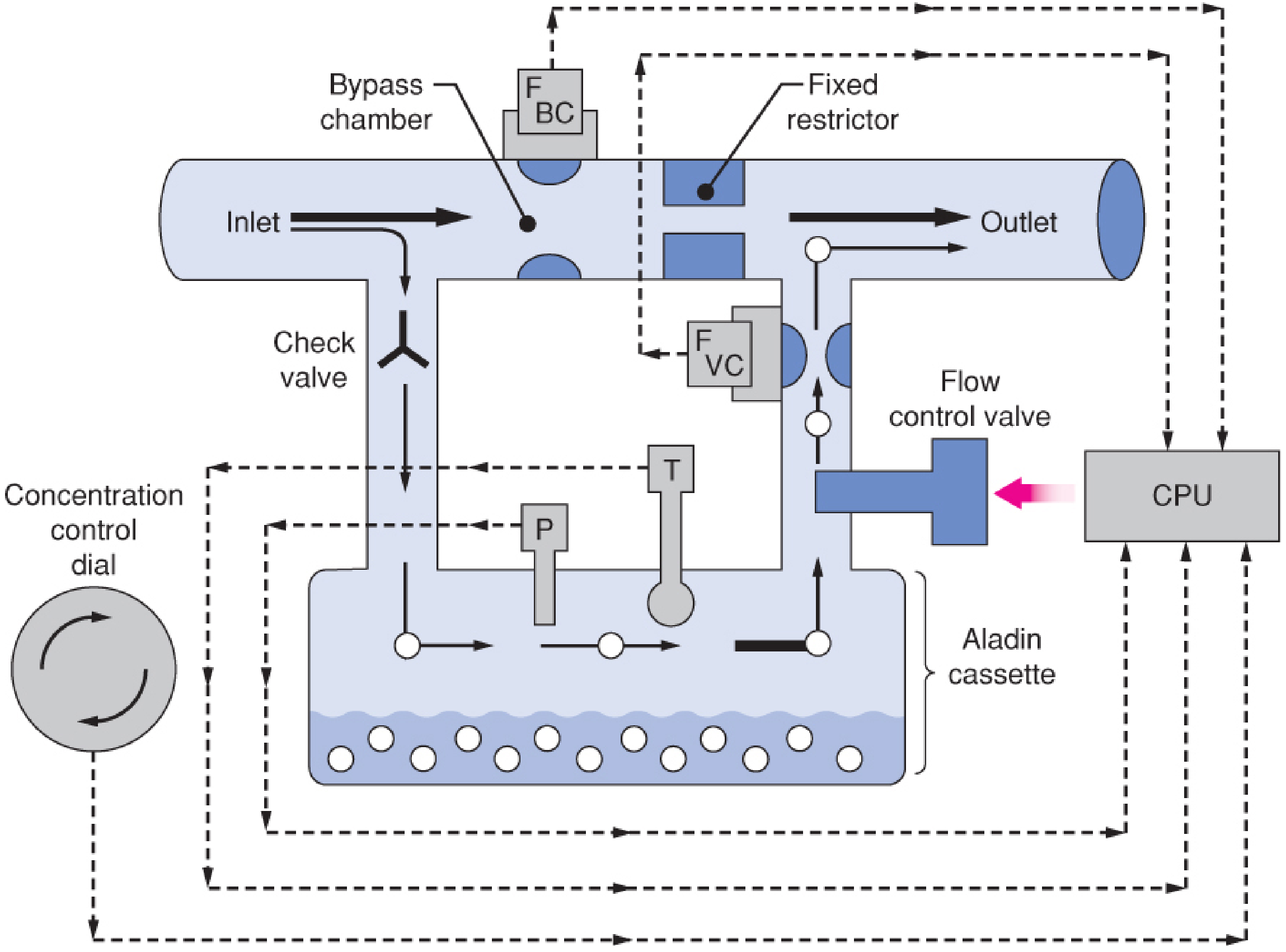
A single permanent internal control unit inside the workstation works with interchangeable, agent-specific Aladin cassettes. One control unit can work with multiple agents.
Aladin Cassette Colour Coding
| Cassette Colour | Agent |
|---|
| Red | Halothane |
| Orange | Enflurane |
| Purple | Isoflurane |
| Yellow | Sevoflurane |
| Blue | Desflurane |
Cassettes are also magnetically coded so the workstation automatically identifies which agent has been inserted.
Operating Principle
Functional anatomy resembles a variable bypass vaporizer (bypass chamber + vaporizing chamber), but the key difference is electronic control:
- Fixed restrictor in bypass chamber
- Flow sensors (FBC and FVC) in both bypass chamber and vaporizing chamber outlet
- Pressure sensor (P) inside the cassette (vaporizing chamber)
- Temperature sensor (T) inside the cassette
- Electronically regulated flow control valve at vaporizing chamber outlet - controlled by a CPU
The CPU receives inputs from: concentration control dial + pressure sensor + temperature sensor + bypass flow sensor + vaporizing chamber outlet flow sensor + carrier gas composition data from flowmeters. It uses all of this to calculate and regulate the exact flow control valve opening needed for the desired output.
This design delivers all agents including desflurane from one platform, because the CPU handles temperature/pressure compensation electronically.
Special Features
- Immune to tipping - no orientation restrictions for storage or transport
- Overfilling protection mechanism
- Valves automatically close when cassette is removed from workstation (prevents fresh gas loss and liquid agent entering gas line)
- Can deliver desflurane without a separate heated/pressurized circuit
TYPE 4: INJECTION-TYPE VAPORIZER
Classification
- Electronically controlled, injection (liquid injection), agent-specific, out-of-circuit
- Examples: Maquet vaporizer (FLOW-i workstations); Dräger DIVA (Direct Injection of Volatile Agent)
Operating Principle
Instead of vaporizing liquid by flowing gas over it, these devices directly inject liquid anesthetic in precise pulses into a heated vaporizing chamber:
- Reservoir holds liquid anesthetic
- Drive gas (from the anesthesia machine) pressurizes the reservoir - this pressure drives liquid through the injector and minimizes evaporation within the reservoir
- Liquid is injected in microprocessor-controlled pulses into a heated vaporizing chamber where rapid evaporation occurs
- Injection continues in small increments until the desired volume is delivered
- Total injection per interval is calculated from: desired concentration × FGF through the vaporizer
- A dedicated gas analyzer downstream monitors actual output
Dräger DIVA Variant
- Consists of an interchangeable vaporizing module + gas supply arrangement built into the workstation
- Liquid anesthetic flows by gravity from a reservoir into a dosing chamber
- From the dosing chamber it is injected into the heated vaporizing chamber
- Agent-specific modules
Advantages of Injection Vaporizers
| Feature | Benefit |
|---|
| No wicks | Not vulnerable to tipping; no wick saturation needed |
| Microprocessor-controlled | Precise, consistent delivery independent of FGF rate |
| Can fill during use | No need to stop (though output pauses during filling in Maquet) |
| Alarms | Alarm at <10% level; high-priority alarm at <5% |
| Auto pre-use check | Automatically tested for function and leaks daily |
IN-CIRCUIT vs. OUT-OF-CIRCUIT: THE FIRST CLASSIFICATION
| Feature | Out-of-Circuit | In-Circuit (Draw-Over) |
|---|
| Location | Upstream in fresh gas line | Within the breathing circuit |
| Resistance to flow | Not relevant | Must be low (patient breathes through it) |
| Modern use | All modern anaesthesia machines | Resource-constrained settings, field anaesthesia, ICU sedation |
| Example | Tec 7, Vapor 2000, Tec 6, Aladin | Oxford Miniature Vaporizer (OMV), Goldman |
| FGF driving force | Machine flowmeter pressure | Patient's own respiratory effort (draw-over) |
Draw-Over Vaporizers (In-Circuit)
- Patient's inspiratory effort draws gas over the liquid anesthetic
- Must have very low resistance
- No pressurized gas source required
- Used in military/field anaesthesia and resource-limited settings
- Examples: Oxford Miniature Vaporizer (OMV), PAC vaporizer
FACTORS THAT INFLUENCE VAPORIZER OUTPUT (Barash 9e)
| Factor | Effect on Variable Bypass | Effect on Tec 6 |
|---|
| Temperature increase | Output increases (compensated by bimetallic strip) | Automatically compensated electronically |
| Altitude (low pressure) | Vol% increases, partial pressure near constant | Vol% constant, partial pressure decreases |
| High FGF (flow effect) | Minimal at standard flows; may decrease at very high flows | Regulated electronically |
| N2O as carrier | Brief rise then fall in output | Decrease at low FGF; clinically significant |
| Tilting | Liquid floods bypass chamber - overdose risk | Shutoff valve closes - safe |
| Intermittent back-pressure (pumping effect) | Can transiently increase output | Less relevant due to design |
Pumping Effect (Back-Pressure Effect)
- Occurs when positive pressure ventilation transmits back-pressure into the vaporizer
- Gas is pushed into the vaporizing chamber, picks up extra vapour, then exits as a bolus during expiration
- Results in higher output than dialed
- Modern vaporizers minimize this with check valves and anti-pumping devices; the Dräger Vapor 2000 has a long inlet tube specifically to reduce this
SAFETY FEATURES COMMON TO MODERN VAPORIZERS
- Agent-specific filling systems - colour-coded, indexed fill ports to prevent misfilling
- Vaporizer interlock systems - prevent simultaneous use of two vaporizers on the same back-bar (Selectatec system)
- Temperature compensation - automatic adjustment for evaporative cooling
- Overfilling protection - fill port positioned at the safe maximum level
- Anti-tipping mechanisms (or automatic shutoff if tilted)
- Anti-pumping devices - check valves reduce back-pressure effect
QUICK COMPARISON TABLE - ALL VAPORIZER TYPES
| Feature | Variable Bypass (Tec 7) | Dual-Circuit (Tec 6) | Cassette (Aladin2) | Injection (Maquet/DIVA) |
|---|
| Agents | All except desflurane | Desflurane only | All incl. desflurane | Agent-specific |
| Mechanism | Flow-over, wick-based | Electrically heated blender | Electronic + flow-over | Liquid injection + heated chamber |
| Temperature compensation | Mechanical (bimetallic) | Electronic (thermostat) | Electronic (CPU) | Electronic |
| Heated? | No | Yes (39°C) | No (for non-des agents) | Yes (vaporizing chamber) |
| Altitude effect (partial pressure) | Minimal | Significant (decreases) | Varies | Not fully reported |
| Tipping risk | Yes | No (shutoff valve) | No | No |
| Control | Concentration dial | Concentration dial | CPU via dial | Electronic interface only |
| Interchangeable? | No | No | Yes (cassettes) | Agent-specific modules |
EXAM MNEMONICS AND HIGH-YIELD POINTS
- Variable bypass vaporizers = "VF-TASO": Variable bypass, Flow-over, Temperature-compensated, Agent-specific, out-of-circuit
- Why desflurane can't use variable bypass: High SVP (boil risk) + High MAC (cooling) + High bypass flow required
- Tec 6 = dual-gas blender, NOT a true vaporizer
- Aladin uses one hardware unit for all agents - the cassette provides the agent-specific vaporizing chamber
- Injection vaporizers have no wicks - immune to tipping
- Tec 6 at altitude: vol% constant, partial pressure falls (unlike variable bypass where partial pressure is near constant)
- Copper Kettle / Verni-Trol = historical measured-flow (bubble-through) vaporizers - now obsolete
Miller's Anesthesia, 10e, Chapter 20 (pp. 2276-2312) | Barash Clinical Anesthesia, 9e, Chapter 25 (pp. 1969-1998)