
Describe the three-point pressure system and its role in orthotic design in detail explain
Describe the three-point pressure system and its role in orthotic design in detail explain
orthoses AND biomechanics
three point pressure system orthosis biomechanics
https://www.physio-pedia.com/Foundations_for_Ankle_Foot_Orth…
Three-point pressure system
- One primary corrective force applied at or near the segment/joint that needs to be controlled
- Two counterforces applied in the opposite direction, one proximal and one distal to the primary force
Basic arrangement
Counterforce 1        Primary force        Counterforce 2
       ↓                    ↑                    ↓
       |                    |                    |
Proximal segment        Area to control      Distal segment
- A posteriorly directed force at the proximal calf
- An anteriorly directed force at the knee region
- A posteriorly directed force at the distal tibia
Mechanical basis
- The longer the distance between the corrective force and counterforces, the less force is needed to produce the same corrective moment.
- Short orthoses must apply higher forces to obtain comparable control, increasing the risk of pain, skin injury, and poor tolerance.
Components of the system
1. Primary force
- Medial force at the knee to resist genu valgum
- Lateral force at the knee to resist genu varum
- Anterior force on the tibia to resist knee hyperextension
- Posterior force on the proximal tibia to resist excessive knee flexion
- Posterior force on the calf or tibia to influence ankle position in an AFO
2. Proximal counterforce
3. Distal counterforce
Pressure versus force
- A small contact area produces high pressure and may cause pain, redness, skin breakdown, or pressure sores.
- A larger, well-contoured contact area reduces local pressure and improves comfort.
Role in orthotic design
1. Control of angular movement
- Limit excessive flexion or extension
- Resist varus or valgus movement
- Control inversion or eversion
- Improve alignment during standing and walking
- Slow progression of a flexible deformity
- Maintain a corrected position after surgical or nonsurgical treatment
2. Alignment correction
- Correcting flexible knee valgus or varus
- Controlling calcaneal varus or valgus
- Reducing excessive ankle plantarflexion or dorsiflexion
- Managing flexible spinal curves with a thoracolumbosacral orthosis
3. Distribution of load
- Fibular head
- Tibial crest
- Malleoli
- Patella
- Navicular prominence
- Metatarsal heads
- Areas with impaired sensation, edema, fragile skin, or bony prominence
4. Orthosis suspension and stability
Examples in common orthoses
| Orthosis/problem | Primary force | Counterforces | Intended effect |
|---|---|---|---|
| AFO for plantarflexion control | Posterior force on lower leg or anterior force through tibial shell, depending on design | Opposing forces at foot and other lower-leg contact areas | Influence ankle position and tibial progression in gait |
| Ground-reaction AFO | Anterior force over proximal tibia | Posterior forces through heel and distal tibia/foot | Creates an external knee-extension moment, useful in selected crouch gait patterns |
| Knee orthosis for genu valgum | Medially directed force at knee | Laterally directed forces above and below knee | Creates a varus corrective moment |
| Knee orthosis for genu varum | Laterally directed force at knee | Medially directed forces above and below knee | Creates a valgus corrective moment |
| KAFO for genu recurvatum | Anterior force near knee | Posterior force on calf and distal tibia | Produces a knee-flexion moment to oppose hyperextension |
| Spinal orthosis for scoliosis | Force at curve apex | Opposing forces above and below the apex | Produces a corrective bending moment and assists trunk alignment |
Design factors that determine effectiveness
Direction of force
Location of force application
Lever-arm length
Material stiffness
Fit and contour
Patient factors
- Skin integrity and sensation
- Edema or limb-volume changes
- Spasticity, weakness, contracture, or joint instability
- Body weight and activity level
- Ability to put on, remove, and manage the orthosis
- Gait pattern and functional goals
Clinical precautions
- Pain
- Redness persisting after device removal
- Blisters, skin breakdown, or ulceration
- Nerve compression, particularly near the fibular head
- Reduced circulation
- Device rejection and nonuse
Summary
- Control unwanted joint or segment motion
- Correct or contain flexible deformity
- Improve alignment during function
- Distribute force safely across the limb
- Reduce pain and improve stability or gait
i want with example explanation
orthoses AND biomechanics
three point pressure force system orthoses examples AFO knee orthosis
Three-point pressure system: explanation with examples
- One main corrective force at the joint or deformity to be controlled
- Two opposing counterforces, one above and one below the main force
Simple diagram
Counterforce              Corrective force              Counterforce
     ↓                           ↑                           ↓

Upper segment            Joint/deformity              Lower segment
Example 1: AFO to prevent foot drop
Force arrangement
Back of calf                 Front of ankle/tibia              Under the foot
     ↓                                ↑                              ↓

   Posterior                    Anterior                    Plantar support
 counterforce                corrective force               counterforce
How it works
- The foot tends to fall into plantarflexion.
- The AFO applies an anteriorly directed corrective force over the lower leg.
- Counterforces act through the posterior calf region and the footplate.
- Together, the forces create a dorsiflexion moment.
- This resists plantarflexion and helps maintain toe clearance during swing.
Functional result
- Less toe dragging
- Safer walking
- Improved heel contact at initial contact
- Better lower-limb stability in selected patients
Example 2: Knee brace for genu valgum
Force arrangement
Outer thigh                  Inner side of knee                 Outer calf
     →                              ←                                →

Proximal counterforce       Corrective force              Distal counterforce
How it works
- The knee tends to move medially into valgus.
- The brace applies a medially directed force at the lateral side of the knee.
- It applies laterally directed counterforces on the outer thigh and outer calf.
- These three forces create a rotational force that moves the knee toward varus.
- The result is reduced valgus alignment or valgus loading.
Important point
- Improve alignment during activity
- Reduce dynamic valgus movement
- Improve stability
- Shift load away from an overloaded knee compartment in selected cases
Example 3: Knee brace for genu varum
Force arrangement
Inner thigh                  Outer side of knee                  Inner calf
     →                              ←                                →

Proximal counterforce       Corrective force              Distal counterforce
How it works
- The brace applies a laterally directed force near the knee.
- Counterforces act medially above and below the knee.
- This creates a valgus moment.
- In a medial compartment unloading knee brace, the purpose may be to reduce load passing through a painful medial knee compartment.
Example 4: Cervical collar
For limiting neck flexion
Back of head                  Chin/mandible                  Upper chest
     →                              ←                              →

Counterforce                 Corrective force                Counterforce
How it works
- The chin support provides a posteriorly directed force.
- The occiput and upper chest provide anteriorly directed counterforces.
- This limits excessive neck flexion.
Example 5: Spinal brace for scoliosis
Example: right thoracic curve
Upper trunk                  Rib prominence                    Lower trunk
     ←                              →                               ←

Counterforce                 Corrective force                Counterforce
How it works
- The main pad presses on the rib prominence near the apex of the curve.
- Counterforces act above and below the curve on the opposite side.
- The resulting moment attempts to reduce lateral bending and control curve progression.
Why braces are made long
Long lever arm
Counterforce ------------------ Joint ------------------ Counterforce
         Large distance = less force needed
Short lever arm
Counterforce ---- Joint ---- Counterforce
      Small distance = more force needed
- A short AFO may not adequately control the knee.
- A KAFO has longer lever arms and can provide stronger control of knee alignment.
- A spinal orthosis needs sufficient trunk coverage to effectively influence spinal motion.
Practical design rules
-
Correct force direction
The main force must oppose the unwanted movement. -
Adequate distance between forces
Wider spacing gives a better lever arm and needs less force. -
Broad contact areas
Pressure equals force divided by area. Wider pads or shells reduce harmful local pressure. -
Relief over bony prominences
Avoid excessive force over the fibular head, malleoli, patella, tibial crest, and other vulnerable areas. -
Secure suspension
If the orthosis slips or rotates, the forces no longer act at the intended points. -
A functional goal
The aim may be to correct a flexible deformity, resist movement, improve gait, reduce pain, protect healing tissue, or redistribute load.
In one sentence
to drawable diageram
A clear educational medical line diagram of the three-point pressure system in an ankle-foot orthosis. Show a simple side view of a lower leg and foot inside an AFO brace, with exactly three large arrows: one anteriorly directed corrective force at the front of the tibia, and two posteriorly directed counterforces at the back of the calf and beneath the foot. Label the three forces clearly as Primary corrective force, Proximal counterforce, and Distal counterforce. Show a curved arrow at the ankle labeled Dorsiflexion moment. Include a small title: Three-point pressure system in an AFO.
three point pressure system ankle foot orthosis biomechanics
Three-point pressure system in an AFO
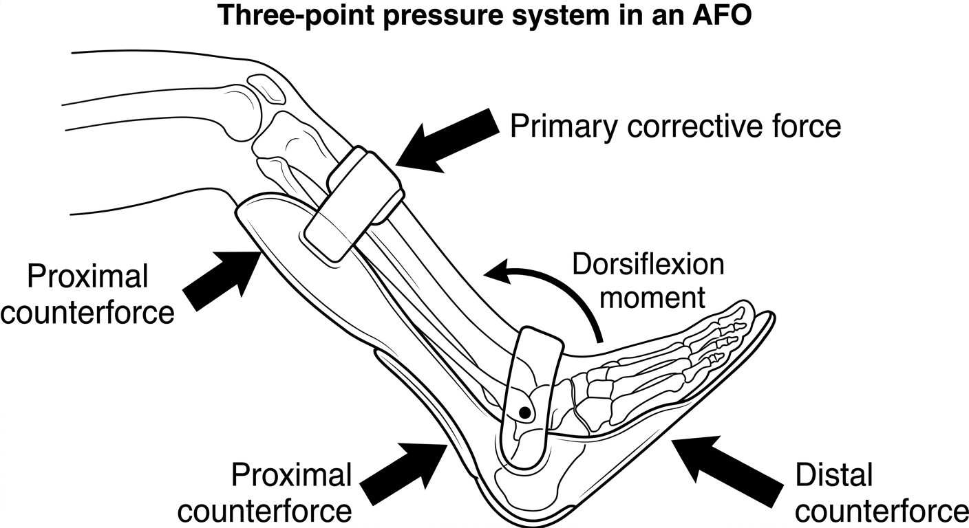
                 LOWER LEG

       Posterior calf
       counterforce
            ←
            │
            │              Anterior force
            │              at tibia
            │                  →
            │                  │
            │                  │
            │               [ ANKLE ]
            │                  ↶
            │          Dorsiflexion moment
            │
    ______________________________
   /                              \
  /             FOOT               \
 /__________________________________\
             ←
      Distal counterforce
       from foot plate
How to draw it step by step
- Draw a simple side view of the lower leg and foot, making an L-shape.
- Draw an AFO behind the calf and under the foot.
- At the front of the lower leg, draw an arrow pointing backward or forward according to your chosen convention. Label it:
Primary corrective force. - At the back of the upper calf, draw an arrow in the opposite direction. Label it:
Proximal counterforce. - Under the foot plate, draw another arrow in the same direction as the calf counterforce. Label it:
Distal counterforce. - Draw a curved arrow around the ankle and label it:
Dorsiflexion moment - prevents plantarflexion/foot drop.
Key idea to write under the diagram
The AFO applies one corrective force at the tibia and two opposing counterforces at the calf and foot. These three forces create a dorsiflexion moment at the ankle, helping prevent excessive plantarflexion and toe drag in foot drop.