
vertebral roatation surgery
vertebral rotation surgery scoliosis derotation techniques
Bailey and Love's Short Practice of Surgery 28th Edition
Page 542
spinal deformity correction surgical approaches vertebral derotation outcomes
Bailey and Love's Short Practice of Surgery 28th Edition
Page 542
vertebral rotation scoliosis surgical correction
Hugging Face pmc clinical VQA raw
Page 0
Vertebral Rotation Surgery
Why Vertebral Rotation Matters
- Coronal plane: lateral curvature (measured by Cobb angle)
- Sagittal plane: loss of normal kyphosis/lordosis
- Axial/transverse plane: vertebral rotation — often the most functionally significant component, causing rib hump and trunk imbalance
Indications for Surgery
| Condition | Surgical Trigger |
|---|---|
| Adolescent Idiopathic Scoliosis (AIS) | Cobb angle >45–50°, progressive curve |
| Congenital Scoliosis | Progressive curves, vertebral anomalies |
| Neuromuscular Scoliosis | Functional impairment, cardiopulmonary compromise |
| Adult Degenerative Scoliosis | Pain, neurological deficit, progression |
Surgical Techniques for Vertebral Derotation
1. Rod Rotation (Cotrel-Dubousset Technique)
- Classic technique: a pre-contoured rod is placed in the coronal plane then rotated 90°
- Converts the lateral curve into sagittal contour
- Achieves indirect vertebral derotation
- Limitation: incomplete axial derotation, can cause "adding-on" or flat back
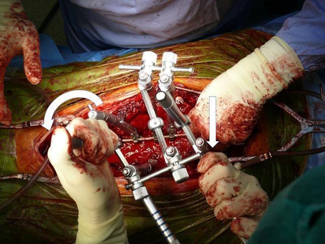
2. Direct Vertebral Rotation (DVR)
- Vertebral Column Manipulator (VCM) or similar device attached to pedicle screws at the apex
- Applies a controlled rotational force en bloc across multiple apical vertebral levels
- Corrects the apical vertebral rotation directly in the transverse plane
- Superior to rod rotation for 3D correction
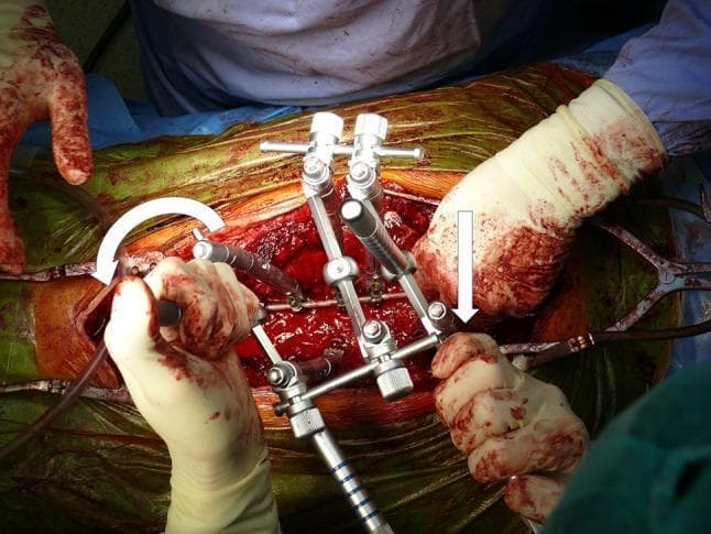
See intraoperative image below demonstrating DVR using a VCM construct:
3. Apical Vertebral Derotation (AVD)
- Individual derotation maneuvers applied sequentially to each vertebra using derotation handles on pedicle screws
- More precise control per level compared to en bloc techniques
- Commonly combined with DVR
4. Hemivertebra Excision
- Used in congenital scoliosis with a fully segmented hemivertebra
- Excision of the anomalous vertebra removes the asymmetric growth driver
- Followed by short-segment fusion
- Bailey & Love's (p. 542) identifies this as a primary surgical option for progressive congenital curves
5. Posterior Instrumented Correction and Fusion (PICF)
- Standard approach for most scoliosis types
- Pedicle screws inserted bilaterally across multiple levels
- Rod contouring + rotation + compression/distraction maneuvers applied
- Fusion achieved with bone graft/allograft
6. Growing Rod Constructs (Pediatric Patients)
- Magnetically Controlled Growing Rods (MCGR): non-invasive lengthening via external magnet
- Used in skeletally immature children to control curve while allowing spinal growth
- Definitive fusion deferred until near skeletal maturity (Bailey & Love's, p. 542)
Surgical Approach
| Approach | Use Case |
|---|---|
| Posterior (most common) | AIS, neuromuscular, most deformities |
| Anterior | Thoracolumbar/lumbar curves, disc release for rigid curves |
| Combined anterior-posterior | Severe/rigid curves (>70–80°), revision cases |
| Lateral (XLIF/OLIF) | Adult degenerative scoliosis, disc space correction |
Instrumentation
- Pedicle screws: the workhorse — provide 3-column fixation and enable rotational correction
- Hooks and wires: older adjuncts, still used in select cases
- Rods: titanium or cobalt-chrome; shape pre-contoured to desired sagittal profile
- Cross-links: add construct rigidity
Intraoperative Monitoring
- Neuromonitoring (SSEP + MEP): mandatory during derotation maneuvers to detect spinal cord compromise
- Wake-up test: if neuromonitoring changes occur
- Fluoroscopy / intraoperative CT (O-arm): confirm screw placement and deformity correction
Complications
| Complication | Rate / Notes |
|---|---|
| Neurological deficit | <1% with modern monitoring |
| Screw malposition | 5–15%; most clinically silent |
| Infection (deep) | 1–4%; higher in neuromuscular patients |
| Pseudarthrosis / non-union | 2–5%; risk increases with longer constructs |
| Proximal/distal junctional kyphosis | 5–40% depending on definition; long-term concern |
| Implant failure | Rod breakage, especially at lumbosacral junction |
| Crankshaft phenomenon | Growth around a fused spine in immature patients |
Outcomes
- Modern posterior instrumented fusion with DVR achieves 50–70% correction of Cobb angle and significant improvement in axial rotation
- Patient-reported outcomes (SRS-22, ODI scores) show substantial quality-of-life improvement
- Fusion rates >95% with current techniques
- Long-term: most AIS patients lead normal, active lives post-surgery
Summary
Ligaments around? Cranium cervical junction. Anatomy.
ligaments craniovertebral junction anatomy occipital atlas axis
alar ligament transverse ligament tectorial membrane cruciate ligament craniocervical
craniovertebral junction ligaments anatomy diagram
craniovertebral junction ligaments anatomy alar transverse tectorial membrane
https://thejns.org/focus/view/journals/neurosurg-focus/38/4/…
https://www.anatomystandard.com/ossa-et-juncturae/columna-ve…
apical ligament anterior atlanto-occipital membrane posterior atlanto-occipital membrane anatomy craniocervical
Ligaments of the Craniovertebral Junction
Anatomical Overview
- Atlanto-occipital joints (C0-C1): paired synovial joints; primary motion = flexion/extension (~25°)
- Median atlantoaxial joint (C1-C2): pivot joint around the dens; primary motion = rotation (~45° each side)
- Lateral atlantoaxial joints (C1-C2): paired synovial facet joints
PRIMARY STABILIZING LIGAMENTS
1. Transverse Ligament of the Atlas (Transverse Atlantal Ligament)
- The single most important stabilizer of the atlantoaxial joint
- Origin: Medial tubercle of the lateral mass of C1 (one side)
- Insertion: Medial tubercle of the lateral mass of C1 (opposite side)
- Course: Runs horizontally posterior to the dens, binding it against the anterior arch of C1
- Function: Constrains the dens within 3 mm of the anterior ring of atlas; prevents anterior subluxation of the atlas; permits rotation while preventing dangerous anterior displacement
- Clinical note: Tears typically occur laterally at the tubercle attachments; rupture = atlantoaxial instability
2. Cruciform (Cruciate) Ligament of the Atlas
- The transverse ligament + its vertical extensions form a cross shape
- Vertical component (longitudinal bands):
- Superior crus: from transverse ligament upward to the anterior margin of the foramen magnum (clivus), between the apical ligament and tectorial membrane
- Inferior crus: from transverse ligament downward to the posterior surface of the C2 body
- The vertical component is relatively weak and contributes little to stability - the transverse portion does the heavy lifting
3. Alar Ligaments
- Together with the transverse ligament, the most critical stabilizers of the CVJ
- Origin: Posterolateral surface of the upper dens (anterolateral in some descriptions)
- Insertion: Medial aspect of the occipital condyles, inferior to the foramen magnum; travel caudocranially (50%) or horizontally (50%)
- Shape: V-shaped - narrowest at origin, wider at insertion
- Function:
- Primary: Limit axial rotation of the cranium (each alar ligament limits rotation to the contralateral side)
- Secondary: Limit lateral flexion contralaterally
- Tertiary: Secondary stabilizer if transverse ligament ruptures - prevents anterior displacement
- Clinical note: Strong; injury = craniocervical instability; alar ligament tears visible on MRI T2
MEMBRANES (Broad Sheet-like Ligaments)
4. Tectorial Membrane
- Rostral continuation of the posterior longitudinal ligament (PLL)
- Origin: Posterior surface of C2 body
- Insertion: Anterior margin of the foramen magnum (occipital bone/clivus)
- Course: Runs posterior to the dens and cruciform ligament; in intimate contact with the dura mater; composed of three layers
- Function:
- Posterior border of the supraodontoid space (apical cave)
- Prevents the odontoid from folding backward into the brainstem during flexion
- Limits extension and flexion
- Clinical note: Second most important stabilizer after the transverse ligament; tectorial membrane injuries common in children after trauma
5. Anterior Atlanto-occipital Membrane
- Origin: Upper margin of the anterior arch of C1
- Insertion: Anterior rim of the foramen magnum (clivus)
- Reinforcement: The more superficial anterior atlanto-occipital ligament (dense band); medially reinforced by the anterior longitudinal ligament
- Laterally: Fuses with atlanto-occipital joint capsule
- Function: Limits extension at C0-C1; forms the anterior wall of the supraodontoid space
6. Posterior Atlanto-occipital Membrane
- Rostral continuation of the ligamentum flavum
- Origin: Posterior arch of the atlas (C1)
- Insertion: Posterior margin of the foramen magnum
- Lateral margins: Blend with posteromedial joint capsule
- Important relations: The vertebral artery and C1 nerve root pass through gaps in this membrane laterally - a key surgical landmark
- Function: Minor contribution to stability; limits flexion
7. Anterior Atlanto-axial Membrane
- Thin elastic membrane connecting anterior arch of C1 to anterior body of C2
- Considered the cranial extension of the anterior longitudinal ligament
- Fuses laterally with capsule of lateral atlantoaxial joint
8. Posterior Atlanto-axial Membrane
- Broad thin membrane connecting posterior arch of C1 to posterior surface of C2 lamina
- Rostral continuation of the ligamentum flavum
- The C2 nerve root exits through this membrane
SECONDARY / ACCESSORY LIGAMENTS
9. Apical Ligament of the Dens
- A fibrous remnant of the notochord
- Origin: Apex of the dens
- Insertion: Anterior margin of the foramen magnum (basion), between the two alar ligaments
- Surroundings: Surrounded by fatty tissue within the supraodontoid space
- Function: Weak; minimal stabilizing role - may be absent in up to 20% of individuals
- Clinical note: Often mistaken for a fracture on imaging
10. Capsular Ligaments (Atlanto-occipital and Atlantoaxial)
- Relatively thick fibrous capsules enclosing each synovial joint
- Occipitoatlantal capsular ligaments: the key stabilizers of the atlanto-occipital joint (research shows isolated injuries of transverse/alar/tectorial ligaments alone do NOT cause OA instability - the capsules must be injured)
- The lateral atlantoaxial capsules allow rotation but prevent distraction
11. Accessory Atlanto-axial Ligament (Y-ligament)
- Located near the lateral border of the tectorial membrane, partially covered by it
- Most commonly connects axis (C2) to both the atlas (C1) and occipital bone
- Variable but reported in most individuals
12. Transverse Occipital Ligament
- Small ligament connecting both occipital condyles, running posterosuperior to the alar ligaments
- Prevalence >50%
- Not in standard anatomical nomenclature (Terminologia Anatomica)
13. Barkow's Ligament
- Runs anterior to the dens and alar ligaments
- Connects the occipital condyles anteriorly
- Variable; not in standard nomenclature
14. Lateral Atlanto-occipital Ligament
- Short ligament running from the jugular process of the occiput to the transverse process of C1
- Homolog of the intertransverse ligaments of the subaxial spine
EXTRINSIC LIGAMENTS (Continuations from Subaxial Spine)
| Ligament | Subaxial Equivalent | CVJ Role |
|---|---|---|
| Tectorial membrane | Posterior longitudinal ligament | Critical - limits flexion, protects brainstem |
| Anterior atlanto-occipital/axial membrane | Anterior longitudinal ligament | Limits extension |
| Posterior atlanto-occipital/axial membrane | Ligamentum flavum | Minor stability |
| Nuchal ligament | Supraspinous + interspinous ligaments | C7 to external occipital protuberance; limits flexion |
Functional Summary
| Motion Limited | Primary Ligament(s) |
|---|---|
| Anterior atlas displacement | Transverse ligament (cruciform complex) |
| Excessive rotation (C1 on C2) | Alar ligaments |
| Dens posterior displacement into cord | Tectorial membrane |
| Atlanto-occipital joint stability | Occipitoatlantal capsular ligaments |
| C0-C1 extension | Anterior atlanto-occipital membrane |
| C0-C1 flexion | Posterior atlanto-occipital membrane, tectorial membrane |
Clinical Pearls
- Trauma assessment: The three most critical ligaments to evaluate for CVJ instability on MRI (T2, within 72 hours of injury) are the transverse ligament, alar ligaments, and tectorial membrane - once torn, these are irreparable
- Jefferson fracture (C1 burst): may disrupt the transverse ligament - the Rule of Spence (>7 mm lateral overhang on open-mouth view) predicts transverse ligament rupture
- Rheumatoid arthritis: synovial pannus erodes the transverse ligament - commonest cause of non-traumatic atlantoaxial instability
- Down syndrome: ligamentous laxity affects alar and transverse ligaments - atlantoaxial instability screening mandatory before sports
- Odontoid fractures: spare the transverse ligament but disrupt its functional anchor
Create a detailed visual atlas or reference poster of CVJ ligaments and attachments
Detailed medical reference poster of craniovertebral junction (CVJ) ligaments anatomy. Dark navy blue background, clean clinical illustration style. Show three views arranged on the poster: TOP LEFT - POSTERIOR VIEW (tectorial membrane removed): Show occiput, C1 atlas, C2 axis bones in 3D perspective. Label and color-code: Cruciform/Cruciate ligament (transverse band in bright yellow crossing behind dens, with superior crus going up to foramen magnum and inferior crus going down to C2 body), Alar ligaments (paired, orange-red, V-shaped going from dens laterally to occipital condyles), Apical ligament (small green ligament from dens tip to basion), Transverse occipital ligament (small purple band connecting occipital condyles), Accessory atlanto-axial ligament (gray). TOP RIGHT - SAGITTAL CROSS-SECTION (midline): Show clivus/basion at top, foramen magnum, C1 anterior and posterior arches, dens of C2, C2 body. Label and color-code: Tectorial membrane (wide blue band running from C2 posterior body to clivus, posterior to cruciform), Anterior atlanto-occipital membrane (green, anterior arch C1 to foramen magnum rim), Posterior atlanto-occipital membrane (purple, posterior arch C1 to posterior foramen magnum), Apical ligament (thin yellow line apex of dens to basion), Cruciform ligament vertical component (orange), Anterior longitudinal ligament continuation below, Ligamentum flavum continuation below. Show spinal cord and brainstem as light gray structures for context. BOTTOM CENTER - ANTERIOR/SUPERIOR VIEW looking down: Show dens surrounded by transverse ligament (thick bright yellow band), atlas ring, occipital condyles. Alar ligaments shown fanning out obliquely from dens to condyles. Label supraodontoid space / apical cave. Show the V-shaped configuration of alar ligaments clearly. BOTTOM - TABLE: Color-coded legend table with columns: Ligament Name | Color | Origin | Insertion | Primary Function. List all 10 key ligaments. Title at top: "CRANIOVERTEBRAL JUNCTION — Ligament Anatomy Reference" in white bold. Subtitle: "Occiput (C0) · Atlas (C1) · Axis (C2)". Add small labels for: Foramen magnum, Clivus/Basion, Dens (odontoid process), Anterior arch C1, Posterior arch C1, Occipital condyles. Clinical, educational, high-detail medical illustration.
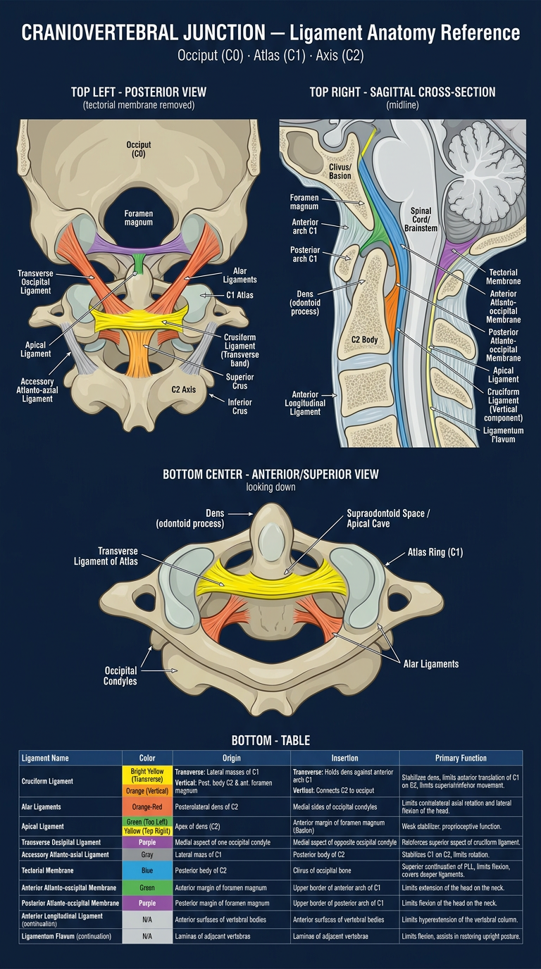
- Posterior view (tectorial membrane removed) - showing the cruciform ligament, bilateral alar ligaments, apical ligament, and accessory structures
- Sagittal cross-section - showing the layered arrangement of the tectorial membrane, atlanto-occipital membranes, and their relationships to the dura and brainstem
- Superior/axial view - showing the transverse ligament gripping the dens posteriorly and the V-shaped spread of the alar ligaments to the occipital condyles
- Color-coded legend table - with origin, insertion, and function for each structure
- The transverse ligament sits directly behind the dens as its primary restraint
- The tectorial membrane (blue broad band) is the rostral PLL - the posterior sentinel against dens migration into the brainstem
- The alar ligaments (orange-red, V-shaped) are the strongest rotational check-reins
- The anterior and posterior atlanto-occipital membranes cap the C0-C1 articulation anteriorly and posteriorly
Give information on aminoglycoside in orthopaedics
Give me information on clostridium tetani in orthopedics
aminoglycoside use orthopaedic surgery bone infection gentamicin cement spacer
Clostridium tetani tetanus prophylaxis open fracture orthopedic wound management guidelines
Aminoglycosides in Orthopaedics
Mechanism & Spectrum
Key Orthopaedic Applications
1. Antibiotic-Loaded Bone Cement (ALBC)
- Gentamicin is the most commonly used agent added to polymethylmethacrylate (PMMA) cement, both commercially premixed (e.g., Palacos R+G) and surgeon-hand-mixed
- Tobramycin is also widely used, sometimes combined with vancomycin for broader coverage
- Used in:
- Primary joint arthroplasty (hip/knee) - some surgeons use it prophylactically, though evidence and stewardship concerns are mixed
- Two-stage revision for periprosthetic joint infection (PJI) - high-dose antibiotic cement spacers are placed after removal of infected implants, delivering very high local antibiotic concentrations with minimal systemic absorption
- Infected non-unions and chronic osteomyelitis - antibiotic beads/spacers (e.g., PMMA beads on a wire, or resorbable calcium sulfate carriers) fill dead space and deliver local antibiotic
- Local elution is effective but there is a well-documented risk of emergence of resistant coagulase-negative staphylococci with long-term low-dose gentamicin cement use
- High-dose antibiotic cement spacers can produce systemic absorption sufficient to cause nephrotoxicity, particularly in patients with renal impairment - serum aminoglycoside levels should be monitored in high-dose spacer cases
- Local aminoglycoside delivery largely avoids the systemic ototoxicity/nephrotoxicity risk seen with IV dosing, which is the main advantage over systemic use
2. Systemic Use for Bone and Joint Infections
- Aminoglycosides (typically gentamicin) are used as part of combination empiric therapy for open fracture-related infections, septic arthritis, and osteomyelitis, especially when Gram-negative or Pseudomonas coverage is needed (e.g., puncture wounds through athletic shoes - classic Pseudomonas osteochondritis)
- Often combined with a penicillin or cephalosporin for synergy against staphylococci in severe infections
- Systemic use is limited by nephrotoxicity and ototoxicity, requiring therapeutic drug monitoring (peak/trough levels) and dose adjustment for renal function - this limits long-term systemic use in prolonged osteomyelitis courses, favoring local delivery instead
3. Open Fracture Prophylaxis
- In Gustilo-Anderson Type III open fractures, some protocols add an aminoglycoside to a first-generation cephalosporin for broader Gram-negative coverage, particularly in heavily contaminated or farm-related injuries
4. Local Delivery Systems Beyond Cement
- Antibiotic-impregnated calcium sulfate beads, collagen sponges, and other resorbable carriers loaded with tobramycin/gentamicin are used in infected wound beds and osteomyelitis defects, avoiding a second surgery for bead removal (unlike PMMA)
Clostridium tetani in Orthopaedics
Microbiology
Why It Matters in Orthopaedics
Tetanus-Prone Wound Features
- Age >6 hours since injury
- Contamination with soil, feces, saliva
- Puncture-type mechanism, devitalized tissue, or significant crush component
- Signs of sepsis
Prophylaxis Protocol (Open Fracture Management)
| Immunization status | Recommended action |
|---|---|
| Booster within last 5 years | No further treatment needed |
| >5 years since booster, or incomplete series | Give tetanus toxoid (Tdap/Td); add Human Tetanus Immune Globulin (HTIG) if wound is tetanus-prone |
| >10 years since booster, or immunocompromised, or unknown/incomplete vaccination history | Tetanus toxoid AND HTIG (250-500 IU IM) |
Integration into Open Fracture Protocol
- Sterile dressing, hemostasis, splinting
- Tetanus prophylaxis assessment and administration
- Parenteral antibiotics (cephalosporin +/- aminoglycoside for Type III, +/- penicillin/metronidazole for fecal or farm contamination given anaerobic/clostridial risk)
- Operative debridement, ideally without excessive delay
- Delayed wound closure once clean
Clinical Presentation Relevant to Orthopaedic Wards
- Incubation typically 3-21 days post-injury
- Trismus (lockjaw) is often the earliest sign, followed by generalized rigidity, opisthotonus, and reflex spasms triggered by minimal stimuli
- Autonomic instability (labile BP, tachycardia) in severe generalized tetanus
- Diagnosis is clinical - no rapid confirmatory lab test exists, making prevention the priority
Key Teaching Point
Give me information on clostridium tetani in orthopedics
Clostridium tetani in Orthopaedics
Microbiology
Why It Matters in Orthopaedics
Tetanus-Prone Wound Features
- Age >6 hours since injury
- Contamination with soil, feces, saliva
- Puncture-type mechanism, devitalized tissue, or significant crush component
- Signs of sepsis
Prophylaxis Protocol (Open Fracture Management)
| Immunization status | Recommended action |
|---|---|
| Booster within last 5 years | No further treatment needed |
| >5 years since booster, or incomplete series | Give tetanus toxoid (Tdap/Td); add Human Tetanus Immune Globulin (HTIG) if wound is tetanus-prone |
| >10 years since booster, or immunocompromised, or unknown/incomplete vaccination history | Tetanus toxoid AND HTIG (250-500 IU IM) |
Integration into Open Fracture Protocol
- Sterile dressing, hemostasis, splinting
- Tetanus prophylaxis assessment and administration
- Parenteral antibiotics (cephalosporin +/- aminoglycoside for Gustilo-Anderson Type III, +/- penicillin/metronidazole for fecal or farm contamination given anaerobic/clostridial risk)
- Operative debridement, ideally without excessive delay (within 6 hours where possible)
- Delayed wound closure once clean
Clinical Presentation Relevant to Orthopaedic Wards
- Incubation typically 3-21 days post-injury
- Trismus (lockjaw) is often the earliest sign, followed by generalized rigidity, opisthotonus, and reflex spasms triggered by minimal stimuli
- Autonomic instability (labile BP, tachycardia) in severe generalized tetanus
- Diagnosis is clinical - no rapid confirmatory lab test exists, making prevention the priority
Key Teaching Point
Convert this into pdf
mkdir -p /tmp/workspace/tetanus-orthopedics && ls -la /tmp/workspace/
~/tetanus-orthopedics/generate_pdf.py
#!/usr/bin/env python3
from reportlab.lib.pagesizes import LETTER
from reportlab.lib.units import inch
from reportlab.lib import colors
from reportlab.platypus import (
    SimpleDocTemplate, Paragraph, Spacer, Table, TableStyle,
    ListFlowable, ListItem, HRFlowable
)
from reportlab.lib.styles import getSampleStyleSheet, ParagraphStyle
from reportlab.lib.enums import TA_LEFT, TA_CENTER

DOC_PATH = "/tmp/workspace/tetanus-orthopedics/Clostridium_tetani_in_Orthopedics.pdf"

styles = getSampleStyleSheet()

title_style = ParagraphStyle(
    "TitleStyle", parent=styles["Title"], fontSize=20, textColor=colors.HexColor("#1a3a5c"),
    spaceAfter=4, alignment=TA_LEFT
)
subtitle_style = ParagraphStyle(
    "SubtitleStyle", parent=styles["Normal"], fontSize=11, textColor=colors.HexColor("#555555"),
    spaceAfter=16, alignment=TA_LEFT
)
h1_style = ParagraphStyle(
    "H1", parent=styles["Heading1"], fontSize=14, textColor=colors.HexColor("#1a3a5c"),
    spaceBefore=14, spaceAfter=6, borderPadding=0
)
h2_style = ParagraphStyle(
    "H2", parent=styles["Heading2"], fontSize=12, textColor=colors.HexColor("#2d6187"),
    spaceBefore=10, spaceAfter=4
)
body_style = ParagraphStyle(
    "Body", parent=styles["Normal"], fontSize=10, leading=14, spaceAfter=6, alignment=TA_LEFT
)
bullet_style = ParagraphStyle(
    "Bullet", parent=styles["Normal"], fontSize=10, leading=14, leftIndent=12, spaceAfter=3
)
note_style = ParagraphStyle(
    "Note", parent=styles["Normal"], fontSize=9.5, leading=13, spaceAfter=6,
    textColor=colors.HexColor("#333333"), backColor=colors.HexColor("#f2f6fa"),
    borderPadding=8, borderColor=colors.HexColor("#c9d9e8"), borderWidth=0.5
)
source_style = ParagraphStyle(
    "Source", parent=styles["Normal"], fontSize=8.5, leading=12, textColor=colors.HexColor("#666666"),
    spaceBefore=10
)

story = []

# Title
story.append(Paragraph("Clostridium tetani in Orthopaedics", title_style))
story.append(Paragraph("Clinical reference: microbiology, tetanus-prone wound assessment, and prophylaxis in orthopaedic trauma", subtitle_style))
story.append(HRFlowable(width="100%", thickness=1, color=colors.HexColor("#1a3a5c")))
story.append(Spacer(1, 10))

# Microbiology
story.append(Paragraph("Microbiology", h1_style))
story.append(Paragraph(
    "<i>Clostridium tetani</i> is an anaerobic, spore-forming, Gram-positive bacillus found ubiquitously "
    "in soil, dust, and animal/human feces. Spores are highly resistant and germinate in low-oxygen "
    "(anaerobic) wound environments, producing <b>tetanospasmin</b>, a potent neurotoxin that blocks "
    "inhibitory neurotransmitter release at spinal synapses, causing generalized muscle rigidity and spasm.",
    body_style
))

# Why It Matters
story.append(Paragraph("Why It Matters in Orthopaedics", h1_style))
story.append(Paragraph(
    "Orthopaedic trauma, especially <b>open fractures, crush injuries, puncture wounds, and heavily "
    "contaminated wounds</b>, creates the exact anaerobic, devitalized tissue environment "
    "<i>C. tetani</i> spores need to germinate. Every open fracture patient must be risk-stratified "
    "and prophylaxed.",
    body_style
))

# Tetanus-prone wound features
story.append(Paragraph("Tetanus-Prone Wound Features", h1_style))
story.append(Paragraph("Wounds are considered tetanus-prone if they involve any of:", body_style))
bullets = [
    "Age greater than 6 hours since injury",
    "Contamination with soil, feces, or saliva",
    "Puncture-type mechanism, devitalized tissue, or significant crush component",
    "Signs of sepsis",
]
story.append(ListFlowable(
    [ListItem(Paragraph(b, bullet_style), bulletColor=colors.HexColor("#1a3a5c")) for b in bullets],
    bulletType="bullet", start="circle"
))

# Prophylaxis Protocol Table
story.append(Paragraph("Prophylaxis Protocol (Open Fracture Management)", h1_style))
table_data = [
    ["Immunization Status", "Recommended Action"],
    ["Booster within last 5 years", "No further treatment needed"],
    ["More than 5 years since booster,\nor incomplete series",
     "Give tetanus toxoid (Tdap/Td); add Human Tetanus\nImmune Globulin (HTIG) if wound is tetanus-prone"],
    ["More than 10 years since booster,\nor immunocompromised, or unknown/\nincomplete vaccination history",
     "Tetanus toxoid AND HTIG (250-500 IU IM)"],
]
tbl = Table(table_data, colWidths=[2.5*inch, 3.6*inch])
tbl.setStyle(TableStyle([
    ("BACKGROUND", (0, 0), (-1, 0), colors.HexColor("#1a3a5c")),
    ("TEXTCOLOR", (0, 0), (-1, 0), colors.white),
    ("FONTNAME", (0, 0), (-1, 0), "Helvetica-Bold"),
    ("FONTSIZE", (0, 0), (-1, -1), 9.5),
    ("GRID", (0, 0), (-1, -1), 0.5, colors.HexColor("#c9d9e8")),
    ("ROWBACKGROUNDS", (0, 1), (-1, -1), [colors.white, colors.HexColor("#f2f6fa")]),
    ("VALIGN", (0, 0), (-1, -1), "MIDDLE"),
    ("LEFTPADDING", (0, 0), (-1, -1), 6),
    ("RIGHTPADDING", (0, 0), (-1, -1), 6),
    ("TOPPADDING", (0, 0), (-1, -1), 6),
    ("BOTTOMPADDING", (0, 0), (-1, -1), 6),
]))
story.append(tbl)
story.append(Spacer(1, 8))
story.append(Paragraph(
    "<b>Important principle:</b> wound severity should not be the sole determinant of the need for "
    "prophylaxis. Immunization status drives the decision, since even minor wounds have caused tetanus "
    "in under-immunized patients.",
    note_style
))

# Integration into Open Fracture Protocol
story.append(Paragraph("Integration into Open Fracture Protocol", h1_style))
story.append(Paragraph("Standard sequence for open fractures:", body_style))
steps = [
    "Sterile dressing, hemostasis, splinting",
    "<b>Tetanus prophylaxis assessment and administration</b>",
    "Parenteral antibiotics (cephalosporin +/- aminoglycoside for Gustilo-Anderson Type III, "
    "+/- penicillin/metronidazole for fecal or farm contamination given anaerobic/clostridial risk)",
    "Operative debridement, ideally without excessive delay (within 6 hours where possible)",
    "Delayed wound closure once clean",
]
story.append(ListFlowable(
    [ListItem(Paragraph(s, bullet_style)) for s in steps],
    bulletType="1", start="1"
))
story.append(Paragraph(
    "Some protocols specifically add <b>metronidazole</b> or high-dose penicillin in heavily "
    "contaminated (farm, fecal) wounds because of anaerobic clostridial species risk. This does not "
    "replace the need for tetanus toxoid/HTIG: antibiotics treat the bacterium and reduce toxin "
    "production, but they do not neutralize toxin already bound to neurons. That is the separate role "
    "of immunoglobulin.",
    body_style
))

# Clinical Presentation
story.append(Paragraph("Clinical Presentation Relevant to Orthopaedic Wards", h1_style))
clinical = [
    "Incubation typically 3-21 days post-injury",
    "<b>Trismus (lockjaw)</b> is often the earliest sign, followed by generalized rigidity, "
    "opisthotonus, and reflex spasms triggered by minimal stimuli",
    "Autonomic instability (labile blood pressure, tachycardia) in severe generalized tetanus",
    "Diagnosis is clinical; no rapid confirmatory lab test exists, making prevention the priority",
]
story.append(ListFlowable(
    [ListItem(Paragraph(c, bullet_style)) for c in clinical],
    bulletType="bullet", start="circle"
))

# Key Teaching Point
story.append(Paragraph("Key Teaching Point", h1_style))
story.append(Paragraph(
    "Most tetanus cases in developed countries now occur after <b>minor, seemingly trivial trauma</b> "
    "in inadequately immunized (often elderly) patients rather than dramatic open fractures. Prophylaxis "
    "assessment should therefore be routine for every wound seen in orthopaedic and emergency settings, "
    "not reserved for severe injuries.",
    note_style
))

# Sources
story.append(Spacer(1, 6))
story.append(HRFlowable(width="100%", thickness=0.5, color=colors.HexColor("#c9d9e8")))
story.append(Paragraph(
    "<b>Sources:</b> Harrison's Principles of Internal Medicine 22E, Ch. 157 \"Tetanus\"; "
    "Tintinalli's Emergency Medicine, \"Tetanus\" and \"Tetanus prophylaxis\"; Roberts and Hedges' "
    "Clinical Procedures in Emergency Medicine, \"Tetanus Immunoprophylaxis\"; PMC review \"Treatment "
    "principles in the management of open fractures\"; EAST Practice Management Guideline - Open "
    "Fractures Prophylactic Antibiotics.",
    source_style
))

doc = SimpleDocTemplate(
    DOC_PATH, pagesize=LETTER,
    topMargin=0.7*inch, bottomMargin=0.7*inch, leftMargin=0.7*inch, rightMargin=0.7*inch,
    title="Clostridium tetani in Orthopaedics"
)
doc.build(story)
print("PDF created at:", DOC_PATH)
cd /tmp/workspace/tetanus-orthopedics && python3 generate_pdf.py
Clostridium tetani in Orthopedics
PDF Document · PDF