
Screw retained single implant cementation detail answer write up
screw retained single implant crown cementation detail clinical prosthodontics
https://pmc.ncbi.nlm.nih.gov/articles/PMC4253117
"screw-retained" AND "implant crown" AND cementation
screw retained implant crown access channel abutment
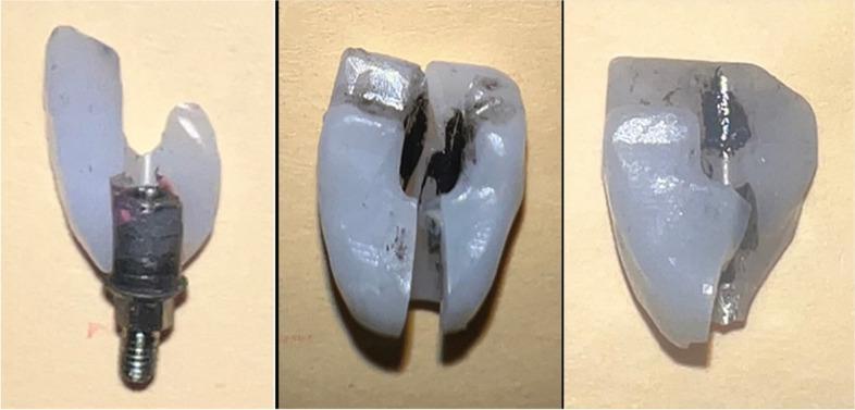
This clinical image illustrates the failure modes of screw-retained dental implant crowns following fracture resistance testing. The composite figure presents three distinct specimens showing catastrophic fractures of the prosthetic crown material. In the first specimen (left), the crown is severely fractured, exposing the underlying titanium abutment insert and screw assembly, which appears structurally intact despite the prosthetic failure. The middle and right specimens demonstrate longitudinal fracture patterns originating at the occlusal surface and propagating through the screw access channel, a known structural weak point in angulated implant restorations. The fractures reveal internal remnants of the resin cement layer and the hollow geometry of the screw channel. These images serve as an educational resource in prosthodontics for understanding mechanical stress distribution in implant-supported monolithic or layered crowns and the influence of screw access design on restoration longevity and failure morphology.
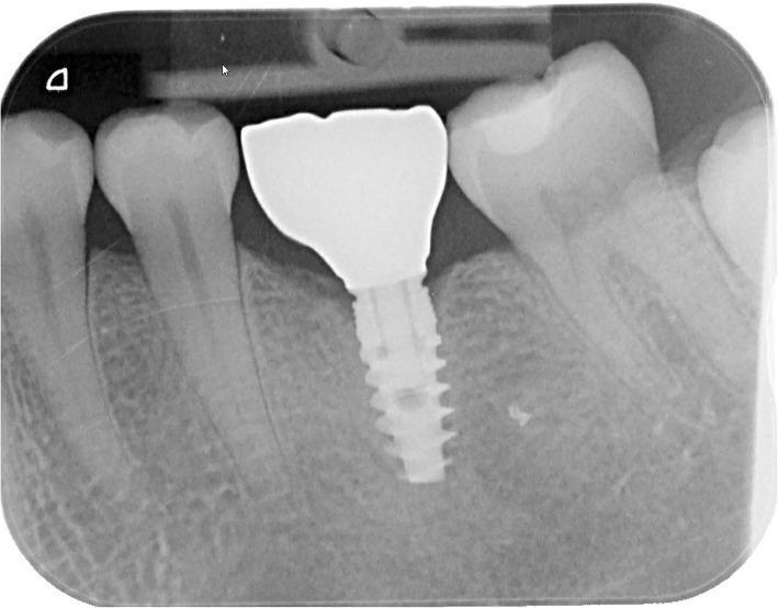
This diagnostic intraoral periapical radiograph displays a screw-retained dental implant and restoration in a mandibular molar position. The dental implant is a highly radiopaque, endosseous threaded fixture exhibiting excellent osseointegration with no visible peri-implant radiolucency. The crestal bone levels are stable, maintained at the level of the implant-abutment interface (platform), comparable to the interproximal bone height of the adjacent natural teeth. Superior to the implant is a full-contour zirconia crown restoration, characterized by a uniform, high radiopacity and an anatomically contoured occlusal surface aligned with the neighboring dentition. A faint vertical radiolucency within the crown suggests the path of the internal screw access channel. The surrounding alveolar bone demonstrates a healthy trabecular pattern. The adjacent teeth show intact periodontal ligament spaces and lamina dura, providing a clinical baseline for evaluating long-term implant success and marginal bone stability one year post-loading.
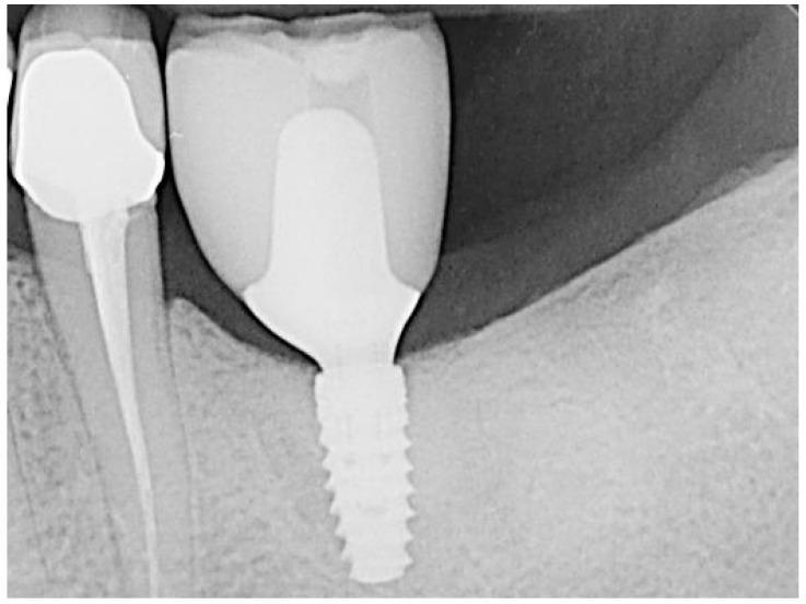
This periapical radiograph shows a completed prosthetic restoration in the mandibular left region (regio 36). The primary focus is a single-tooth dental implant featuring a radiopaque, threaded cylindrical implant body well-integrated into the alveolar bone. A custom radiopaque abutment is visible, supporting a screw-retained lithium disilicate crown, which appears as a moderately radiopaque, well-contoured structure with an internal access channel. The peri-implant bone levels appear stable with no signs of radiolucent defects or peri-implantitis. Adjacent to the implant, the mesial tooth demonstrates a large radiopaque coronal restoration and evidence of prior endodontic treatment, characterized by a uniform radiopaque filling material extending through the root canal to the apex. The periodontal ligament space and surrounding lamina dura of the adjacent tooth remain intact. The imaging demonstrates successful prosthetic rehabilitation following alveolar ridge preservation (ARP) and implant surgery.
Screw-Retained Single Implant Crown: Detailed Write-Up
1. Definition and Concept
2. Components Involved
| Component | Description |
|---|---|
| Implant fixture | Osseointegrated titanium body in the alveolar bone |
| Implant abutment / Ti-base | Connects implant to crown; may be stock or custom |
| Prosthetic retaining screw | Passes through the crown into the implant internal connection |
| Screw access channel | Vertical channel through the crown body for screw driver access |
| Screw access channel filling | Cotton pellet + composite resin seal |
3. Indications
- Implant position permits a screw channel exit through a non-esthetic/favorable area (central fossa of posterior teeth, cingulum of anteriors)
- Patient requires retrievability for maintenance
- Deep subgingival margins where cement control is difficult
- History of peri-implant disease or elevated biologic risk
- Limited inter-arch space (screw-retained can be thinner than crown + abutment system)
- Digital workflow (CAD/CAM milling of single-piece screw-retained crowns)
- Full-arch implant-supported prostheses
4. Contraindications / When Cement-Retained May Be Preferred
- Unfavorable implant angulation causing screw access to emerge through the incisal edge or labial surface of an anterior crown (esthetic compromise)
- Very limited inter-occlusal space that cannot accommodate the screw channel
- Patient's posterior access is significantly restricted (large tongue, limited mouth opening)
- Cases requiring two-stage abutment delivery (custom abutment placed first to mature peri-implant soft tissue, crown cemented later)
5. Clinical Protocol: Step-by-Step Procedure
Stage 1 - Implant Healing and Referral
- Following surgical implant placement, the surgeon places a healing abutment (gingival former) on the implant fixture.
- For a two-stage protocol, surgical exposure is performed after osseointegration (typically 3-6 months); healing abutment is placed and allowed to shape the peri-implant soft tissue for at least 2 weeks.
- A periapical radiograph is taken to confirm complete osseointegration and verify the implant-abutment interface is fully seated.
Stage 2 - Impression Taking (Open-Tray Technique, Preferred for Single Implants)
- The healing abutment is removed; the implant impression mount (open-tray transfer coping) is placed and its long central screw is tightened.
- A custom or stock open-tray impression tray with a hole directly over the implant site is loaded with polyvinylsiloxane or polyether impression material.
- The tray is seated; after the material sets, the central screw of the mount is accessed through the tray hole and unscrewed.
- The tray is removed with the transfer coping captured in the impression.
- The healing abutment is replaced intraorally to prevent soft tissue collapse.
- In the laboratory, an implant analog is connected to the coping, and a gypsum cast is poured.
Digital workflow alternative: An intraoral scanner captures the implant position using a scan body (scan abutment) placed on the implant. This eliminates physical impressions and is increasingly preferred.
Stage 3 - Laboratory Fabrication
- The dental technician fabricates the crown on a lab analog in the master cast.
- Options include:
- Monolithic zirconia or full-contour crown with a milled screw channel - single piece screwed directly to the implant.
- Ti-base hybrid crown - A titanium base (Ti-base) is bonded extra-orally to a zirconia, lithium disilicate, or PMMA crown before delivery (see Section 8).
- The screw channel is oriented to exit through the occlusal fossa (posterior) or cingulum (anterior).
- For angulated implants, angled screw channel (ASC) abutments allow up to 25-30° of correction so the channel still exits in a favorable position.
Stage 4 - Crown Delivery (Cementation Detail)
- Inspect the crown and verify screw channel orientation.
- Place the crown on the implant analog on the study cast; confirm emergence profile, proximal contacts, and occlusion.
- Take a radiograph or use the analog to confirm full seating.
- Remove the healing abutment.
- Place the crown onto the implant connection - align the internal hex/anti-rotation feature correctly.
- Hand-tighten the screw finger-tight with the appropriate screwdriver.
- Verify proximal contacts using dental floss - contacts should be firm but passable. If tight, return to the lab for adjustment; if open, a new restoration is needed.
- Verify occlusal contacts with articulating paper in both centric occlusion and all excursive movements.
- Adjust as needed (occlusal reduction on the restoration using fine diamond burs under water cooling).
- Take a periapical radiograph to confirm full seating of the crown on the implant - there must be no gap at the implant-crown interface (implant-abutment interface).
- Place a small cotton pellet or Teflon tape plug into the screw channel (above the screw head) to protect the screw from composite material.
- Using a calibrated torque wrench attached to the correct screwdriver tip, tighten the retaining screw to the manufacturer's recommended torque value.
- Typically 25-35 Ncm for titanium or metal-based crowns (varies by implant system).
- Lower torque values (15-20 Ncm) are recommended for full-ceramic (all-zirconia) monolithic crowns where the mating surfaces cannot accommodate as much stress.
- Always follow the specific implant manufacturer's instructions.
- After waiting approximately 10 minutes to allow stress relaxation in the screw joint, a re-torque is applied to ensure the screw is fully tight (recommended by most manufacturers).
- The cotton pellet over the screw head acts as a barrier.
- The channel is filled with composite resin (shade-matched to the crown material) in increments.
- The composite is light-cured and finished/polished to create a smooth, contour-matching seal.
- The access channel should be invisible or inconspicuous in the final restoration.
6. The "Cementation" Aspect: Screw-Retained vs. True Cementation
| Feature | Screw-Retained | Cement-Retained |
|---|---|---|
| Primary retention | Mechanical (screw) | Chemical (cement) |
| Cement used intraorally? | No (or only extraoral bonding of Ti-base) | Yes - cement applied in the oral cavity |
| Peri-implant cement risk | Eliminated | High risk if cement expresses subgingivally |
| Retrievability | Easy - remove composite plug, unscrew | Difficult - risk of crown/abutment damage |
| Access channel | Present (visible as composite-filled hole) | Absent |
| Esthetic compromise | Possible in anteriors | None on crown surface |
7. Torque Values by Implant System (General Reference)
| Implant System | Prosthetic Screw Torque |
|---|---|
| Nobel Biocare (TiUnite) | 35 Ncm |
| Straumann (SLActive) | 35 Ncm |
| Zimmer Biomet | 30 Ncm |
| Astra Tech | 25 Ncm |
| Full-ceramic (zirconia) | 15-20 Ncm |
Always refer to the specific implant manufacturer's instructions for torque values. These figures are general references only.
8. The Screwmentable (Hybrid) Design - Special Cementation Detail
- A titanium base (Ti-base) is screwed onto the implant as the abutment.
- A separate zirconia or ceramic crown with an internal access channel is fabricated.
- Extra-oral cementation: The crown is seated onto the Ti-base outside the mouth; resin cement (e.g., MDP-containing adhesive resin cement such as Panavia or RelyX Unicem) is applied to the Ti-base, the crown is seated, and excess cement is removed completely before it sets - this is the critical cementation step.
- The assembly is light-cured/chemically cured.
- The bonded crown-Ti-base unit is then screwed as one unit into the implant intraorally.
- Sandblast or airborne-particle abrade the Ti-base surface (50 µm alumina).
- Apply MDP monomer primer (e.g., Clearfil Ceramic Primer, Z-Prime Plus) to the metal surface - promotes chemical adhesion.
- Apply resin cement to the inner surface of the zirconia crown.
- Seat the crown onto the Ti-base extra-orally; hold under pressure.
- Remove all excess cement with a probe or brush before curing.
- Cure according to cement manufacturer's instructions.
9. Advantages and Disadvantages
Advantages of Screw-Retained Crowns:
- Eliminates cement-induced peri-implantitis - the leading advantage in the modern era
- Full retrievability - can be removed intact for repair, maintenance, or screw retightening
- Simplified maintenance - hygiene access easier to evaluate
- Lower long-term cost - restorations can be repaired without full replacement
- Better for digital workflows - single-piece milled restorations are precise and efficient
Disadvantages:
- Screw access channel - compromises esthetics in anterior regions; weakens ceramic at the channel walls
- Implant angulation sensitivity - unfavorable angulation may place the channel labially (mitigated by angled screw channel abutments)
- Occlusal adjustments at try-in - frequent screw/unscrew cycles needed for adjustment vs. cement-retained where the abutment stays in place
- Technical complexity - requires precise torque application and proper sealing
10. Complications and Management
| Complication | Cause | Management |
|---|---|---|
| Screw loosening | Under-torque, occlusal overload, parafunctions | Re-torque to correct value; adjust occlusion |
| Screw fracture | Over-torque, metal fatigue, implant misalignment | Remove fractured screw using specialized screw retrieval kit |
| Porcelain/ceramic fracture at access channel | Stress concentration at channel, thin ceramic | Repair with composite; fabricate new crown if severe |
| Composite plug failure | Occlusal wear, inadequate sealing | Remove old composite, place new cotton pellet, re-seal |
| Peri-implant mucositis/peri-implantitis | Rare with screw-retained; possible from other causes | Debridement, occlusal evaluation, maintenance protocol |
11. Current Evidence
- A 2025 meta-analysis (PMID 40458331) comparing cement- vs. screw-retained zirconia single crowns found no significant difference in implant survival or marginal bone loss, but noted higher complication rates with cement-retained due to residual cement.
- A 2024 systematic review on zirconia abutment-supported crowns (PMID 38263555) found screw-retained all-ceramic crowns had comparable marginal bone levels and fewer biological complications than cement-retained alternatives.
- A 2025 meta-analysis on angled screw channel crowns (PMID 40108886) found angled screw channel designs are a viable and esthetically favorable alternative to cement-retained crowns when implant angulation would otherwise be a barrier to screw retention.
12. Clinical Images