
Describe all about filter press and double cone blender.
filter press pharmaceutical engineering working principle construction uses
https://inoxmill.com/working-principle-of-plate-and-frame-fi…
double cone blender pharmaceutical construction working principle uses advantages disadvantages
Filter Press
Definition
Principle
- Rate is directly proportional to the surface area of the filter medium and applied pressure.
- Rate is inversely proportional to the viscosity of the filtrate and the thickness/resistance of the filter cake.
Construction
1. Plates
- Flat, rigid units made of aluminium alloy (sometimes lacquered for protection against corrosive chemicals and to enable steam sterilization in pharmaceutical use).
- Grooved or ribbed on both faces to support the filter cloth and allow the filtrate to drain away.
- Each plate has a central hole (socket) at the top or corner that aligns to form a filtrate channel.
- Indicated by one dot in conventional diagrams.
2. Frames
- Open rectangular units of the same material as the plates.
- Contain an open interior space that serves as the slurry reservoir during filtration.
- Have an inlet port to receive incoming slurry.
- Indicated by two dots in diagrams.
- Frames of different thicknesses are available to vary cake capacity.
3. Filter Medium (Cloth or Paper)
- Sheets of filter cloth (cotton, polypropylene, polyester, nylon) or filter paper are placed between each plate and frame.
- The medium retains solids while allowing liquid to pass through.
- In pharmaceutical "polishing" applications, very fine-pore filter pads are used.
4. Sockets / Ports
- Silicon rubber washers provide sealing at the inlets and outlets.
- For corrosive liquids (e.g., pharmaceutical applications where rubber compatibility is a concern), socketless designs avoiding rubber washers are available.
5. End Plates (Head and Tail)
- A fixed head plate at one end and a movable tail plate at the other.
- The entire assembly is held together by a hydraulic closing device or screw mechanism at a preset pressure.
6. Supporting Framework (Chassis)
- The plates and frames are suspended on horizontal side bars (rails) and can slide along them to open and close the press.
7. Feed and Filtrate Manifold
- Pipe manifold with valves for slurry inlet, filtrate outlet, wash liquor inlet, and air vent.
- The air vent prevents air contamination and assists in effective cake washing.
8. Drip Tray
- Positioned below the assembly to collect the filter cake when the press opens and the cake falls.
Working
Uses
- Pharmaceutical industry: Clarification of pharmaceutical solutions, separation of APIs from reaction mixtures, purification of intermediates, removal of particulates from parenterals and ophthalmic preparations ("polishing"), and processing of biomass.
- Food and beverage: Filtration of juices, syrups, oils, and clarification of beverages.
- Chemical industry: Removal of impurities, solid-liquid separation, and recovery of valuable materials.
- Wastewater treatment: Removal of sludge and dewatering of municipal and industrial effluents.
- Cosmetics, mining, and dye industries.
Merits (Advantages)
- High filtration area - multiple plates and frames in series/parallel substantially increase surface area, enabling processing of large volumes.
- Versatile - handles a wide range of particle sizes, slurry consistencies, and liquid types.
- High solid recovery - the filter cake is relatively dry, and the solids can be washed in situ.
- Adaptable - different micron grades achievable in the same unit using a bypass plate; filtration area can be varied using a blockage plate.
- Suitable for sterile operations - stainless steel construction allows autoclaving; socketless designs available for corrosive pharmaceutical liquids.
- Filter medium can be reused after cleaning.
- Simple construction - easy to disassemble and reassemble.
- Batch washing possible without unloading the cake.
Demerits (Disadvantages)
- Batch operation - not continuous; requires downtime for cake discharge and reassembly.
- Labour intensive - cake discharge and cloth cleaning are manual steps in basic models.
- Limited to slurries - not suitable for very dilute suspensions where cake formation is poor.
- Filter cloth damage - the cloth can tear or blind (clog) over time, requiring replacement.
- Slow compared to centrifugal methods for some slurries.
- Large floor space required for large-scale units.
Double Cone Blender
Definition
Principle
Construction
1. The Double Cone Vessel
- The mixing vessel consists of two conical (truncated cone) sections joined at their widest circular cross-section (the equatorial rim), giving the vessel its characteristic double-cone (biconical) shape.
- The conical ends facilitate uniform mixing by directing material toward the center during rotation, and also enable gravity-assisted complete discharge with minimal residue.
- The vessel is statically balanced, which protects the gearbox and motor from excessive load during rotation.
- Made of stainless steel (SS 316L) for pharmaceutical-grade use to ensure corrosion resistance and GMP compliance.
- The interior is mirror-polished to prevent material adherence and ease cleaning.
2. Loading Port
- A wide mouth opening on the body of the cone through which powder/granules are loaded.
- May be fitted with a manhole cover or charging port lid.
- Loaded to approximately two-thirds of the total volume to ensure adequate mixing (the remaining one-third space allows free tumbling of the material).
3. Discharge Valve
- Located at one of the conical tips (the bottom apex when in discharge position).
- A butterfly valve or slide valve controls discharge.
- Tilting the cone positions the discharge port at the lowest point for complete, gravity-assisted emptying.
4. Drive Mechanism
- An electric motor drives the cone via a gearbox and chain/belt drive.
- The shaft extends through both sides of the cone (trunnion support) and is mounted on bearing supports/stands.
- The cone rotates about its central horizontal axis.
5. Intensifier Bar (Optional)
- In some designs, an intensifier bar (a bar with blades or pegs running through the interior) is added for de-agglomeration of lumps or for blending cohesive powders that may not mix adequately by tumbling alone.
6. Frame / Stand
- A robust structural frame supports the entire rotating assembly at working height.
- The frame is designed with adequate head clearance for the rotating cone.
Working / Operation
-
The blender is positioned with its loading port accessible. Powder or granules are loaded to about two-thirds of the blender's capacity. Overfilling reduces mixing efficiency; underfilling is also suboptimal.
-
The loading port is closed and sealed.
-
The motor is started; the double cone rotates at 30-100 RPM. The optimal speed is determined by the nature of the material.
-
As the cone rotates, the material tumbles inside - moving from one conical end to the other, repeatedly. The cascading motion causes the particles to intermix through convective mixing (bulk movement) and diffusive mixing (random particle redistribution at the surface of the powder bed).
-
Mixing typically takes 15-30 minutes, depending on formulation and batch size.
-
After mixing is complete, the blender is stopped with the discharge valve pointing downward. The valve is opened and the blended material flows out by gravity into a drum or hopper below.
-
For cleaning, the cone can be tilted freely to any angle and the interior accessed through the loading port.
Uses
- Primary use: Production of homogeneous solid-solid mixtures (powder-powder and granule blending) for tablet and capsule formulations.
- Effective mixing of pharmaceutical granules, semolina, starch, coffee, cocoa, chocolate granules/flakes, powdered milk, baby food, detergent granules, soap flakes, artificial fertilizers, plastic powder/pellets, fiberglass.
- De-agglomeration and uniform blending of dry excipients and APIs before compression or filling.
- Industries: pharmaceutical, food, chemical, cosmetic, detergent, fertilizer, and plastics.
Merits (Advantages)
- Gentle mixing - the tumbling action exerts minimal shear, making it ideal for fragile granules that could break down in high-shear mixers (important for tablet granules whose particle size distribution must be preserved).
- Large capacity - can handle large batch volumes (from a few liters to several thousand liters).
- Easy to clean, load, and unload - the conical shape at both ends enables complete gravity discharge with minimal residue; the tilting mechanism aids cleaning.
- Minimum maintenance - simple mechanical design with few moving parts.
- Handles varying bulk densities - effective for blending powders of different densities.
- Minimum attrition - low wear and tear on both the equipment and the product.
- No dead zones - the conical geometry avoids stagnant areas of unmixed material.
Demerits (Disadvantages)
- Not suitable for fine particulates - because the tumbling action provides minimal shear, it cannot adequately de-agglomerate very fine or cohesive powders. Fine particles tend to adhere to each other and resist redistribution by gravity alone.
- Not suitable for ingredients with large differences in particle size distribution - size segregation (demixing) can occur with bidisperse systems.
- High headspace requirement - the rotating double cone sweeps a large vertical arc and needs considerable overhead clearance for installation, which can be a constraint in manufacturing suites with low ceilings.
- Serial dilution needed for low-dose actives - if powders are free-flowing and the active ingredient is present in very small amounts, geometric serial dilution must be performed before loading; direct blending can lead to inadequate distribution.
- Batch process only - cannot be used for continuous manufacturing.
Comparison Summary
| Feature | Filter Press | Double Cone Blender |
|---|---|---|
| Function | Solid-liquid separation (filtration) | Solid-solid mixing (blending) |
| Principle | Pressure filtration through a filter medium | Tumbling/gravity-driven mixing |
| Material handled | Slurries (liquid + suspended solids) | Dry powders and granules |
| Key mechanism | Filter cake formation | Cascading and convective motion |
| Operation | Batch | Batch |
| Key advantage | High surface area; washable cake | Gentle on fragile granules; complete discharge |
| Key limitation | Labour-intensive; cloth blinding | Poor for fine/cohesive powders; high headspace |
| Pharma use | API separation, solution clarification, parenteral polishing | Tablet/capsule blend preparation |
Draw and properly label the drying rate curve explaining the rate relationship with a simple model to mimic the conditions of a simple dryer. Only label diagram
A clean, professional scientific diagram of a drying rate curve with the following exact labels and features: MAIN GRAPH (Drying Rate Curve): - Y-axis labeled "Drying Rate (R) [kg water / m² · h]" - X-axis labeled "Moisture Content (X) [kg water / kg dry solid]" - The curve has three clearly distinct regions connected smoothly: 1. A short rising segment from point A to point B (initial warming-up period) 2. A flat horizontal segment from point B to point C (constant rate period) — this is the highest flat line 3. A falling segment from point C down to point D near the x-axis (falling rate period) — a straight diagonal line going down to the right-to-left direction - Point A: labeled "A — Initial Point (cold/wet solid)" at the left start of the rising section - Point B: labeled "B — Start of Constant Rate Period" where the curve becomes flat - Point C: labeled "C — Critical Moisture Content (Xc)" at the transition between flat and falling - Point D: labeled "D — Equilibrium Moisture Content (X*)" where the curve meets or approaches the x-axis - A vertical dashed line from point C down to the x-axis, labeled "Xc (Critical Point)" - A vertical dashed line from point D to the x-axis, labeled "X* (Equilibrium)" - The flat horizontal line is labeled "Rc — Constant Drying Rate" - Region between B and C labeled "CONSTANT RATE PERIOD — Surface evaporation, free water" with a bracket - Region between C and D labeled "FALLING RATE PERIOD — Bound water, internal diffusion controls" with a bracket - Region between A and B labeled "WARMING-UP PERIOD" with a bracket INSET SIMPLE DRYER MODEL (small box diagram in upper right corner): - A rectangular box labeled "DRYER" - Arrow entering the box from the left labeled "Hot Dry Air (Tg, Yg)" - Arrow exiting the box to the right labeled "Humid Air (Tg_out, Y_out)" - A shape inside the box representing wet solid, labeled "Wet Solid (Ts, X)" - A small upward arrow from the solid labeled "Evaporation (R)" - Below the box: "Assumption: Perfect mixing, uniform T and humidity" Overall: white background, clear black lines, color-coded regions (light blue for constant rate, light orange for falling rate), professional engineering/pharmaceutical textbook style, all text clearly legible
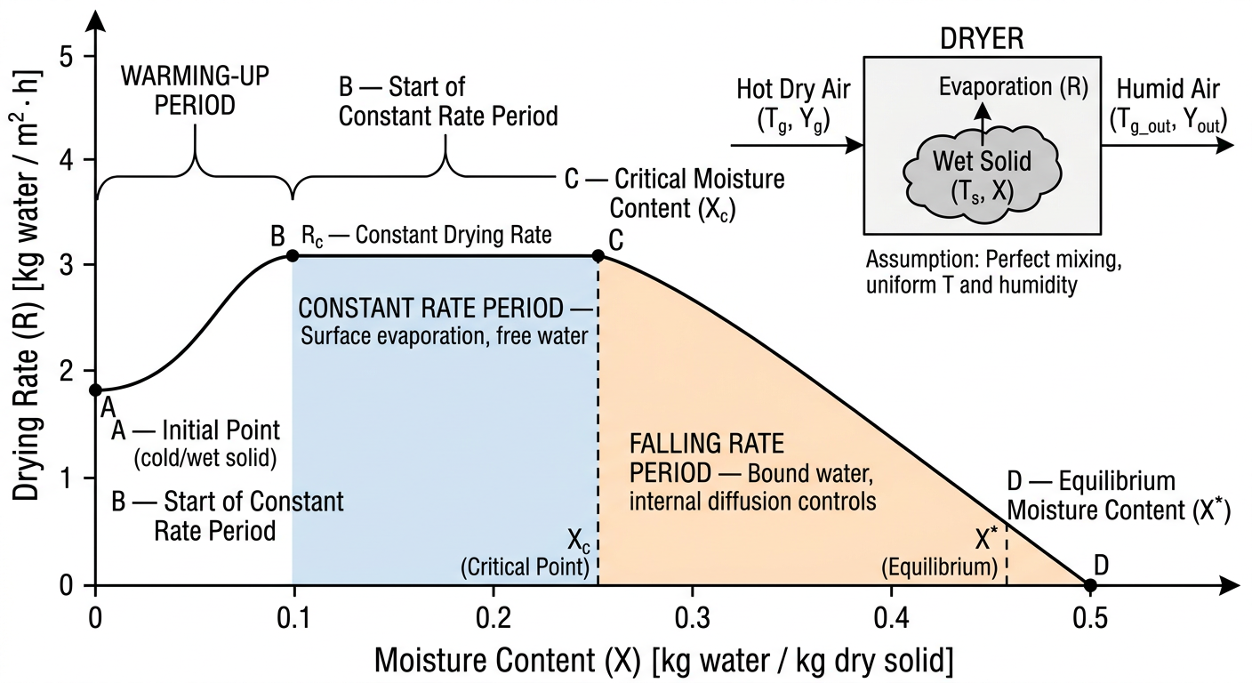
Discuss the principle, construction and working of fluidized bed dryer? In short
Fluidized Bed Dryer (FBD)
Principle
- Every particle is surrounded by hot air on all sides, giving intimate gas-solid contact.
- Heat transfer from hot air to wet solid is rapid.
- Mass transfer (evaporation of moisture) occurs simultaneously from the entire particle surface.
- The result is extremely efficient and uniform drying in a short time.
Construction
- Intake filter (pre-filter + HEPA filter) to supply clean, particle-free air.
- Air heater (steam or electric) to raise air temperature to the desired level (typically 40-80°C for pharmaceuticals).
- A cylindrical or conical stainless steel (SS 316L) bowl that holds the wet material.
- The base has a perforated or mesh distributor plate (the air distribution plate) through which hot air enters from below.
- The cylindrical body expands upward (wider at the top) to reduce air velocity near the top and prevent particle entrainment.
- Located at the top of the expansion chamber.
- Made of nylon or polyester fabric; retain fine particles that are carried upward by the airstream.
- Shaking mechanism (manual or automatic) periodically dislodges trapped fines back into the bed.
- A blower/fan draws air through the system (or pushes from below).
- Exhaust air passes through a final filter before venting to atmosphere.
- Controls inlet air temperature, airflow rate (blower speed), and drying time.
Working
-
Loading: Wet granules (from granulation) are loaded into the product bowl to about one-third to half capacity.
-
Start-up: The blower is switched on. Cold air is first passed to check fluidization, then the heater is activated to deliver hot air at the set temperature.
-
Fluidization: Hot air enters from below through the distributor plate at a controlled velocity. The particles are lifted and suspended - the bed "boils." Each granule is continuously surrounded by hot moving air.
-
Drying: Heat is transferred from hot air to the wet solid by convection. Moisture evaporates from the particle surface and is carried away by the airstream. Initially, drying occurs at a constant rate (free surface moisture evaporating); as the surface dries, it transitions to the falling rate period (internal moisture diffusion controls).
-
Bag shaking: At regular intervals, the filter bags are shaken (manually or by an automatic shaker or by pulse-jet of compressed air) to return accumulated fines back to the product bowl.
-
End point: Drying is complete when the outlet air temperature rises and approaches the inlet temperature (less moisture being evaporated = less cooling). Loss on Drying (LOD) is checked by sampling.
-
Discharge: The blower is stopped, the bowl is removed, and the dried product is discharged.
Merits
- Rapid and uniform drying (large surface area contact)
- Short drying time (15-30 min vs. hours in tray dryer)
- Gentle on granules - minimal attrition
- Easily scalable; suitable for large batch sizes
- Easy to clean (GMP-compliant design)
- Temperature-sensitive materials can be dried at low temperatures
Demerits
- Not suitable for very wet, sticky, or cohesive materials (poor fluidization)
- Fine particles can be entrained and lost; requires good bag filtration
- Risk of electrostatic charge buildup with fine dry powders
- High initial cost
- Cross-contamination risk if bag filters are not properly maintained
- Not ideal for heat-sensitive materials at high temperatures
Discuss the equipents used for coating of tablets and discuss the defects arisen during tablet coating.
Tablet Coating - Equipment and Defects
EQUIPMENT USED FOR TABLET COATING
1. Standard Coating Pan (Conventional Pan)
- A circular, spherical or hexagonal stainless steel pan mounted at an angle of about 40° to the horizontal axis.
- Pan sizes range from 15 cm (lab scale) to 200 cm (production scale).
- Rotated by a variable-speed motor (2-10 RPM).
- A spray gun or ladle is used to apply the coating solution onto the tumbling tablets.
- Hot air is supplied from the front through a duct; exhaust air exits from the same opening or a separate vent.
- Tablets tumble inside the rotating pan.
- Coating solution is sprayed/ladled onto the tumbling bed.
- Hot air evaporates the solvent.
- The process is repeated in multiple sub-coats until the desired coating thickness is achieved.
- Poor air circulation through the tablet bed (air flows over the surface, not through it).
- Long drying times.
- Limited to sugar coating or simple film coating.
- Not suitable for aqueous film coating at large scale.
2. Perforated Pan Coater (e.g., Accela-Cota, Driacoater, Hi-Coater)
- A perforated (baffled) cylindrical drum rotating on its horizontal axis.
- Perforations cover the entire cylindrical surface (Accela-Cota) or only part of it.
- Spray guns (atomizing nozzles) are mounted inside the drum, directed at the tablet bed.
- Inlet hot air is supplied from one side through the perforations and passes through the tablet bed (not just over it).
- Exhaust air exits through perforations on the opposite side.
- Baffles on the inside wall improve tumbling action.
- Tablets tumble in the rotating drum.
- Coating solution is atomized by spray nozzles onto the moving tablet bed.
- Hot air flows through the perforations and directly through the bed - giving much faster and more uniform drying than the conventional pan.
- Suitable for aqueous film coating (fast evaporation needed).
- Faster drying (air passes through the bed).
- Better uniformity of coating.
- Can handle aqueous and organic solvent systems.
- Automation-friendly; process parameters (air temp, spray rate, pan speed) are controllable.
- Accela-Cota - fully perforated drum; most widely used in pharmaceutical industry.
- Driacoater - air is introduced and exhausted through the drum wall via a central hollow shaft; gentle action suitable for friable tablets.
- Hi-Coater - similar perforated pan; spray guns inside the drum.
3. Fluidized Bed Coater (Air Suspension Coater / Wurster Coater)
- A vertical cylindrical chamber with a perforated distributor plate at the base.
- A concentric inner cylinder (the Wurster insert/column) is positioned above the plate with a gap at the bottom.
- Spray nozzle (bottom-spray configuration in Wurster; top-spray or tangential-spray in other configurations) atomizes the coating solution.
- Exhaust filters at the top retain fine particles.
- High-velocity air lifts tablets up through the inner Wurster column past the spray nozzle (coating applied in the spray zone).
- Tablets travel upward through the column, then decelerate and fall back down in the outer annular region (drying zone).
- This up-and-down circulation gives each tablet multiple, uniform coating passes.
- Very efficient drying because tablets are individually suspended in hot air.
- Excellent coating uniformity.
- Ideal for enteric coating, modified-release coating, and microencapsulation.
- Can coat pellets, granules, and small tablets.
- Fast process.
- Not ideal for large, heavy tablets (difficult to fluidize).
- Attrition of friable products possible.
- High capital cost.
4. Immersion Sword / Immersion Tube System
- A modification of the conventional pan in which a perforated tube or sword is immersed directly into the tablet bed.
- Hot air is delivered directly into the bed through the immersed tube, greatly improving drying efficiency.
- Spray nozzle is also immersed.
- Bridges the gap between conventional pan and perforated pan.
DEFECTS IN TABLET COATING
Film Coating Defects
1. Sticking / Picking
- Spray rate too high (tablets too wet before drying occurs).
- Inlet air temperature too low (insufficient drying).
- Pan speed too slow (tablets not moving enough).
- Coating solution concentration too high.
- Reduce spray rate.
- Increase inlet air temperature.
- Increase pan speed.
- Dilute the coating solution.
2. Picking (a specific form of sticking)
- Tablets too wet during coating application.
- Low pan speed; insufficient tablet movement.
3. Bridging
- Coating solution too viscous.
- Excessive coating thickness applied per pass.
- Low spray rate combined with slow pan speed.
- Reduce polymer concentration (lower viscosity).
- Apply thinner coats per pass.
- Increase pan speed.
- Optimize tablet embossing depth (deeper logos help).
4. Cratering
- Spray droplets penetrate the softened coating film before it solidifies; the trapped solvent erupts outward on evaporation.
- Excessive spray rate; droplets too large (low atomization air pressure).
- Coating solution too concentrated.
- Reduce spray rate.
- Increase atomization air pressure (finer droplets).
- Dilute coating solution.
5. Orange Peel / Roughness
- Spray droplets dry too quickly before spreading on the tablet surface (spray drying effect).
- Spray rate too low or drying temperature too high.
- Atomization air pressure too high (droplets too fine; they dry in flight).
- Increase spray rate slightly.
- Reduce inlet air temperature.
- Reduce atomization air pressure.
- Move spray guns closer to the tablet bed.
6. Twinning / Logo Bridging
- Flat-faced tablets with insufficient curvature tend to lie face-to-face.
- Spray rate too high; tablets too wet.
- Pan speed too low.
- Use tablets with curved faces.
- Reduce spray rate; increase pan speed.
7. Film Cracking / Splitting
- Film is brittle - insufficient plasticizer in the formulation.
- Residual internal stress in the film from rapid solvent evaporation.
- Thermal expansion/contraction mismatch between core and film.
- Over-drying.
- Increase plasticizer concentration.
- Reduce drying temperature.
- Allow slower, more gradual drying.
8. Colour Variation / Non-uniform Colour
- Migration of soluble dye to the tablet surface during drying (dye migration).
- Non-uniform spray distribution (poor mixing, spray gun misdirection).
- Insufficient mixing in pan.
- Use insoluble pigments (e.g., aluminium lakes) instead of soluble dyes.
- Ensure proper pan speed and baffling.
- Check spray gun alignment.
9. Mottling
- Soluble dye migration during drying.
- Incompatibility between dye and excipient.
- Use lake colours.
- Distribute colourant more uniformly.
Sugar Coating Defects (Additional)
| Defect | Cause | Remedy |
|---|---|---|
| Rough/uneven surface | Too rapid drying, excess sugar solution | Slow drying; apply thinner coats |
| Cracking of sugar coat | Rapid volume change; too thick individual coats | Apply thinner sub-coats; use softer sealing coat |
| Colour blooming/mottling | Moisture absorption during polishing | Control humidity; ensure complete drying between coats |
| Whiskering | Coat too thin at tablet edges | Ensure adequate build-up at edges |
| Chipping at edges | Friable core; insufficient sealing coat | Improve core hardness; apply adequate sealing |
Summary Table - Equipment Comparison
| Feature | Conventional Pan | Perforated Pan | Fluidized Bed (Wurster) |
|---|---|---|---|
| Air flow | Over the bed | Through the bed | Through and around particles |
| Drying efficiency | Low | High | Very high |
| Coating uniformity | Moderate | Good | Excellent |
| Best for | Sugar coating | Film coating | Film/enteric/modified-release |
| Scale | Small-medium | All scales | Small-medium |
| Aqueous coating | Difficult | Yes | Yes |
| Capital cost | Low | Medium | High |
Discuss the methods used for filling of hard gelatin capsules.
Filling of Hard Gelatin Capsules
A. Manual / Hand Filling (Small Scale)
- Capsule bodies are separated from caps and placed upright in a capsule tray (filling board with holes matching the capsule size).
- The powder/granule formulation is spread over the tray and pushed into the open bodies using a spatula or by gentle tapping.
- Excess powder is swept away and caps are pressed back on.
B. Semi-Automatic Filling (Bench-Top Machines)
C. Automatic / Industrial Filling Methods
1. Auger Fill / Dosing Auger Method
- A rotating auger (screw) within a powder hopper turns at a controlled rate and forces a measured volume of powder into the capsule body by screw-feed displacement.
- The powder mass is maintained at a uniform height in the hopper.
- The auger rotates a fixed number of turns per capsule, delivering a consistent volume of powder.
- The fill weight is controlled by adjusting the auger speed and rotation count.
2. Dosator Method (Dosator Nozzle / Piston-Cylinder Dosator)
- A hollow cylindrical tube (dosator) with a spring-loaded or mechanically controlled piston at its upper end dips into a powder bed of controlled depth and picks up a compacted powder plug by compression, then deposits it into the capsule body.
- The dosator consists of a thin-walled cylinder open at the bottom and a closely fitting piston above.
- An array of dosators operates simultaneously, one per capsule body.
- The dosator descends into the powder bed (which is maintained at a uniform, leveled depth).
- The piston is set at a position that defines the cavity volume - this determines the dose.
- As the dosator penetrates the powder bed, powder compresses inside the cylinder, forming a coherent powder plug held by mild compression and interparticulate friction.
- The dosator is lifted out of the powder bed, carrying the plug.
- The dosator is positioned over the open capsule body.
- The piston moves downward and ejects the plug into the capsule body.
- The cap is rejoined.
- High accuracy of fill weight.
- Fast; widely used in high-speed machines (up to 150,000+ capsules/hour on multi-track machines).
- Used in machines like Zanasi and MG2 series.
- Poor flow powders may give variable plug formation.
- The plug must have sufficient cohesiveness to be retained in the dosator between pickup and ejection - very free-flowing powders may not form a coherent plug (require a lubricant like magnesium stearate).
3. Tamping Pin / Tamp-Fill Method (Disc-Dosing / Dosing Disc Method)
- Powder in a dosing disc (turret) is repeatedly and gently tapped/compressed by a series of tamping pins at successive stations to progressively build up a powder plug of the required weight within a cylindrical bore in the disc. The completed plug is then transferred into the capsule body.
- The dosing disc (segment disc) has multiple bores arranged in a circular pattern.
- Above the disc is a powder hopper that fills the bores by gravity.
- 5 tamping stations (each with a tamping pin) apply progressive compression to the powder in the bore.
- A transfer station ejects the final plug into the capsule body.
- The dosing disc rotates incrementally, carrying each bore through the powder hopper (powder fills by gravity and is leveled).
- At Station 1: a tamping pin descends and applies a light compression - partially compacting the powder in the bore.
- At Stations 2, 3, 4: further tamping pins descend with increasing compression - more powder is added from the hopper after each tamp, building the plug layer by layer.
- At Station 5: final tamping to the desired plug density.
- At the Transfer/Ejection Station: the finished plug is pushed out of the bore by an ejector pin and deposited directly into the waiting capsule body below.
- The cap is rejoined and the filled capsule is ejected.
- Excellent fill weight uniformity.
- High production speed.
- Suitable for a wide variety of formulations.
- Multiple tamping stations allow gradual, gentle plug formation - less likely to damage sensitive particles.
- Requires a degree of powder cohesiveness to form a stable plug.
- Complex mechanism requiring precise calibration of pin depth.
- Not ideal for very free-flowing or very fine powders without optimization.
4. Vibration / Gravity Fill Method
- Powder/granules are fed into capsule bodies purely by gravity and vibration without compression.
- The capsule body is placed directly beneath the hopper outlet.
- A vibrating mechanism assists the powder to flow and settle into the capsule body by gravity.
- A leveling plate removes excess powder from the capsule opening.
5. Liquid / Semi-Solid Filling (Lipid-Based Systems)
- A liquid or thermosoftened semi-solid formulation is pumped into the capsule body and solidifies on cooling.
- The formulation is maintained in a molten/liquid state in a heated reservoir.
- A positive displacement pump or piston-pump dosing system accurately meters the volume into each capsule body.
- The filled capsules pass through a cooling tunnel where the fill solidifies.
- The cap is then closed.
- Excellent bioavailability enhancement for poorly soluble drugs.
- No need for powder flow properties.
- Specialized equipment needed.
- Compatibility of fill with gelatin shell must be verified (risk of shell softening or leakage).
6. Tablet / Pellet / Multi-Particulate Filling
- Mini-tablets (2-3 mm diameter), pellets, or coated multi-unit particulate systems (MUPS) are filled into hard gelatin capsules using a vibration/gravity + counting method or special pellet dosing systems.
- Counting wheels or rotating discs count the exact number of units per capsule.
- Important for modified-release and combination products.
General Steps in Automatic Capsule Filling (Common to All Methods)
| Step | Operation |
|---|---|
| 1. Rectification | Capsules oriented cap-up in the feed hopper |
| 2. Separation | Cap and body mechanically separated and held in bushings |
| 3. Filling | Fill material dosed into the body by the chosen method |
| 4. Rejoining | Cap is pressed onto the body |
| 5. Ejection | Filled capsule ejected and conveyed to deduster/polisher |
| 6. Inspection | Weight check (in-process control) by checkweigher |
Comparison of Principal Filling Methods
| Method | Mechanism | Best for | Accuracy | Speed |
|---|---|---|---|---|
| Auger | Screw feed | Powders, granules | Moderate | High |
| Dosator | Plug pickup by piston-cylinder | Powders, granules | High | Very high |
| Tamping pin (disc) | Progressive compression in disc bore | Powders, granules | Very high | Very high |
| Gravity/vibration | Free-flow into body | Pellets, beads, mini-tablets | Moderate | Moderate |
| Liquid fill | Pump metering | Liquids, semi-solids | Very high | Moderate |
. Define Clinical Literature Evaluation. Enlist its types and explain the process of Evaluation of drug literature. Discuss shortly
Clinical Literature Evaluation
Definition
In short: It is the skill of reading a research paper critically rather than passively accepting its conclusions.
Types of Clinical Literature
1. Primary Literature
- Randomized controlled trials (RCTs)
- Cohort studies, case-control studies
- Cross-sectional studies
- Case reports and case series
- Original pharmacokinetic/pharmacodynamic studies
- Phase I, II, III, IV clinical trials
2. Secondary Literature
- Indexing databases: PubMed/MEDLINE, EMBASE, CINAHL, International Pharmaceutical Abstracts (IPA), Cochrane Library
- Systematic reviews and meta-analyses (some classify these as primary)
- Abstracting services
3. Tertiary Literature
- Textbooks (Goodman & Gilman, DiPiro's Pharmacotherapy)
- Drug compendia (USP, British Pharmacopoeia, Martindale)
- Drug information databases (Micromedex, Lexicomp, Clinical Pharmacology)
- Review articles, monographs
Hierarchy of Evidence (Briefly)
Systematic Review / Meta-analysis (highest)
    ↓
Randomized Controlled Trial (RCT)
    ↓
Cohort Study
    ↓
Case-Control Study
    ↓
Cross-Sectional Study
    ↓
Case Report / Case Series
    ↓
Expert Opinion / Editorials (lowest)
Process of Evaluation of Drug Literature
Step 1: Identify the Type of Study and Purpose
- Determine what kind of study it is: RCT, cohort, meta-analysis, case report, etc.
- Identify the PICO elements:
- P - Population/Patient (who was studied?)
- I - Intervention (what was given/done?)
- C - Comparison (what was the control/comparator?)
- O - Outcome (what was measured?)
- Understand the study objective - is it asking about efficacy, safety, pharmacokinetics, or disease epidemiology?
Step 2: Evaluate the Study Design
- Is the chosen study design appropriate for the research question?
- For efficacy questions: Was it an RCT? (gold standard) Was it randomized, double-blinded, and placebo-controlled?
- For safety/rare events: Was a cohort or case-control design justified?
- Was the study prospective or retrospective? (prospective is generally stronger)
- Was there a control group?
Step 3: Evaluate the Methods
A. Subject Selection (Sampling)
- How were subjects recruited? Were inclusion and exclusion criteria clearly defined and appropriate?
- Was the sample representative of the target population?
- Was the sample size adequate? Was a power calculation done? (Underpowered studies are prone to false-negative results.)
B. Randomization
- Was randomization performed? Was the method described (e.g., computer-generated random numbers)?
- Was allocation concealment ensured? (Prevents selection bias at the time of enrollment.)
C. Blinding
- Was the study single-blind, double-blind, or open-label?
- Double-blind (both patient and investigator unaware of treatment) is the strongest design to reduce performance and detection bias.
D. Outcome Measures
- Were outcomes primary (pre-specified, most important) and secondary clearly defined before the study began?
- Were outcomes clinically meaningful (e.g., mortality, hospitalization) or only surrogate endpoints (e.g., lab values)?
- Were outcomes measured objectively and consistently?
Step 4: Evaluate Results and Statistical Analysis
- Are the descriptive statistics (mean, SD, median, range) appropriate for the data type?
- Is the appropriate statistical test used (t-test, chi-square, ANOVA, log-rank, etc.)?
- What is the p-value? Is p < 0.05 used as the threshold for significance? Was it pre-specified?
- Critical: A statistically significant result (p < 0.05) is not the same as clinically significant.
- What is the effect size?
- For continuous outcomes: Mean difference or Standardized Mean Difference (SMD)
- For dichotomous outcomes: Relative Risk (RR), Odds Ratio (OR), Absolute Risk Reduction (ARR), Number Needed to Treat (NNT)
- Were confidence intervals (CI) reported? Wide CIs indicate imprecision.
- Was there intention-to-treat (ITT) or per-protocol analysis? ITT is preferred for RCTs.
Step 5: Identify Potential Biases
| Type of Bias | Description |
|---|---|
| Selection bias | Non-representative sample or non-random allocation |
| Performance bias | Differences in care other than the intervention |
| Detection bias | Outcome assessors not blinded |
| Attrition bias | High dropout rate; differential loss to follow-up |
| Reporting bias | Selective reporting of significant outcomes only |
| Publication bias | Positive results more likely to be published |
| Confounding | Uncontrolled variables that affect the outcome |
Step 6: Evaluate the Discussion and Conclusions
- Do the conclusions match the results? Authors often overstate findings.
- Are limitations of the study acknowledged honestly?
- Does the study compare findings to previous literature?
- Is the conclusion generalized beyond what the data supports? (overgeneralization)
- Are conflicts of interest (funding source, industry sponsorship) declared? Industry-funded trials are more likely to favor the sponsor's product.
Step 7: Assess Clinical Applicability
- Can the findings be applied to your patient population? (External validity / Generalizability)
- Are the study subjects similar in age, disease severity, comorbidities, and concomitant medications to real-world patients?
- Is the intervention (drug, dose, route) feasible in your clinical setting?
- Do the benefits outweigh the risks in the context of your patient?
- Are the findings consistent with other evidence (systematic reviews, guidelines)?
Summary: Checklist for Drug Literature Evaluation
| Domain | Key Questions |
|---|---|
| Study type | Is it appropriate for the question? |
| Subjects | Representative? Sample size adequate? |
| Randomization | Proper? Allocation concealed? |
| Blinding | Double-blind? |
| Outcomes | Clinically meaningful? Pre-specified? |
| Statistics | Correct test? p-value + CI + effect size? |
| Bias | Sources identified and minimized? |
| Conclusions | Match the data? Limitations stated? |
| Applicability | Relevant to your patient? |
What are various designs of Clinical Trials. Explain exclusion of patients and monitoring a clinical trial. In short
Clinical Trial Designs, Exclusion of Patients, and Monitoring
I. Designs of Clinical Trials
A. Based on Allocation of Intervention
1. Randomized Controlled Trial (RCT)
- Participants are randomly allocated to either the intervention group (receives the drug/treatment) or the control group (receives placebo or standard treatment).
- Randomization eliminates selection bias and balances known and unknown confounders between groups.
- Considered the gold standard for evaluating efficacy and safety.
- Can be single-blind (patient unaware), double-blind (both patient and investigator unaware - preferred), or triple-blind (including statistician unaware).
2. Non-Randomized / Quasi-Experimental Trial
- Treatment allocation is not random (e.g., by patient preference, physician choice, or alternating assignment).
- More prone to selection bias; lower in the evidence hierarchy.
B. Based on Control Group
3. Placebo-Controlled Trial
- Control group receives an inert placebo identical in appearance to the test drug.
- Isolates the pharmacological effect from the placebo effect.
- Ethical only when no effective treatment currently exists.
4. Active-Controlled Trial
- Control group receives a currently accepted standard treatment.
- Used when a placebo would be unethical (e.g., in severe disease where withholding treatment is harmful).
- Aims to show non-inferiority or superiority over the active comparator.
5. Dose-Response Trial
- Multiple dose levels of the same drug are compared to find the optimal dose.
- Important in Phase II trials.
C. Based on Study Design Structure
6. Parallel Group Design
- Each participant is assigned to one group only and receives one treatment throughout the trial.
- Most common design in clinical trials.
- Simple, avoids carryover effects.
7. Crossover Design
- Each participant receives both treatments in sequence, separated by a washout period (to eliminate carryover effect of the first treatment).
- Each participant acts as their own control, reducing inter-individual variability.
- Requires fewer subjects.
- Limitation: Not suitable for diseases that change over time (progressive conditions); washout period must be adequate; carryover effects can still occur.
8. Factorial Design
- Two or more interventions are tested simultaneously in the same trial.
- Participants are randomly allocated to combinations: A alone, B alone, A+B, or neither (2×2 factorial).
- Efficient - tests multiple questions in one trial.
- Example: Testing aspirin AND beta-carotene in the same cardiovascular prevention trial.
9. Withdrawal Design (Enrichment Design)
- All participants first receive the active drug (run-in period).
- Those who respond are then randomized to continue the drug or switch to placebo.
- Evaluates whether continued treatment is necessary to maintain benefit.
10. Adaptive Design
- Allows pre-planned modifications to the trial as data accumulate (e.g., changing sample size, dropping a dose arm, modifying eligibility criteria).
- Guided by interim analyses.
- More flexible and efficient but statistically complex.
11. Cluster Randomized Trial
- Groups (clusters) such as hospitals, clinics, or villages - rather than individual patients - are randomized.
- Used when the intervention is applied at a group level (e.g., a community health intervention).
12. Stepped-Wedge Design
- A type of cluster trial where all clusters eventually receive the intervention, but the timing of crossover from control to intervention is randomized.
- Useful when withholding intervention is ethically difficult.
D. Based on Phase of Drug Development
| Phase | Population | Purpose |
|---|---|---|
| Phase I | Healthy volunteers (20-80) | Safety, tolerability, pharmacokinetics, dose range |
| Phase II | Patients with the target disease (100-300) | Efficacy signals, dose-response, short-term safety |
| Phase III | Large patient population (300-3000+) | Confirm efficacy and safety vs. comparator; support regulatory approval |
| Phase IV | General population post-marketing | Long-term safety, rare ADRs, new indications, pharmacovigilance |
E. Other Design Types
| Design | Description |
|---|---|
| Open-label | Both patient and investigator know the treatment; used in Phase I or when blinding is impractical |
| Single-blind | Only patient is blinded |
| Double-blind | Both patient and investigator are blinded; strongest control of bias |
| Pragmatic trial | Tests treatment under real-world clinical conditions; wide eligibility, flexible protocols |
| Explanatory trial | Tests under ideal, highly controlled conditions to establish biological efficacy |
| N-of-1 trial | Single patient undergoes multiple crossover periods; determines best treatment for that individual |
II. Exclusion of Patients from Clinical Trials
Definition
Purpose of Exclusion Criteria
- Patient safety - protect vulnerable individuals from potential harm.
- Reduce confounding - remove variables that could obscure the true drug effect.
- Improve data quality - ensure a homogeneous study population with interpretable results.
- Ethical and regulatory compliance - protect groups that cannot give informed consent or are at higher risk.
Common Categories of Exclusion
1. Medical / Clinical Exclusions
- Presence of comorbid conditions that could confound results or increase risk:
- Severe renal or hepatic impairment (alters drug metabolism/excretion)
- Uncontrolled hypertension, diabetes, or cardiac disease
- Active malignancy (unless it is the condition being studied)
- Active infections (e.g., HIV, tuberculosis)
- Contraindications to the study drug (known allergy, prior serious ADR)
- Recent surgery or major illness within a defined period
2. Pharmacological Exclusions
- Use of concomitant medications that could interact with the study drug (e.g., strong CYP3A4 inhibitors/inducers)
- Participation in another clinical trial within the washout period
- Known drug or alcohol dependence (affects compliance and results)
3. Physiological / Demographic Exclusions
- Pregnant or breastfeeding women - risk to fetus/infant; ethical and liability concern
- Children / adolescents - unless the trial specifically targets this age group; different pharmacokinetics and ethical protections apply
- Elderly - sometimes excluded from early trials due to polypharmacy and organ dysfunction concerns, though this limits generalizability
- Extremes of body weight
4. Psychological / Compliance Exclusions
- Cognitive impairment or psychiatric illness that prevents informed consent
- History of poor compliance in previous studies
- Inability to follow study protocol (e.g., language barrier, no transport to clinic)
5. Laboratory / Investigation-Based Exclusions
- Abnormal baseline laboratory values beyond defined thresholds:
- e.g., serum creatinine > 2× upper limit of normal
- Platelet count below a specified threshold for trials involving anticoagulants
- Abnormal ECG (QTc prolongation for drugs affecting cardiac conduction)
- Recent abnormal imaging findings
6. Ethical Exclusions
- Lack of informed consent - the most fundamental exclusion; no consent = no participation, regardless of eligibility
- Legally incompetent individuals without a legal representative
Inclusion vs. Exclusion Balance
- Too broad exclusion criteria → Highly selected, unrepresentative population → Poor external validity (results cannot be generalized to real patients).
- Too narrow exclusion criteria → Heterogeneous population → Increased variability, harder to detect treatment effect, increased safety risk.
- The goal is a balance between internal validity (clean data) and external validity (generalizability).
III. Monitoring a Clinical Trial
Definition
Who Monitors a Clinical Trial?
| Role | Responsibility |
|---|---|
| Sponsor | Overall responsibility; appoints monitors and DSMB |
| Clinical Research Associate (CRA) / Monitor | Conducts regular site visits and remote monitoring |
| Data Safety Monitoring Board (DSMB) / Data Monitoring Committee (DMC) | Independent committee reviews interim efficacy and safety data |
| Regulatory Authority | FDA, EMA, DCGI inspect trial sites for GCP compliance |
| Institutional Review Board (IRB) / Ethics Committee | Ongoing ethical oversight |
| Principal Investigator (PI) | Day-to-day oversight at the study site |
Key Components of Trial Monitoring
1. Site Monitoring Visits
- Verify informed consent was properly obtained and documented for every participant.
- Check that eligibility criteria (inclusion/exclusion) were correctly applied.
- Review source documents against the Case Report Forms (CRFs) - called Source Data Verification (SDV).
- Confirm that the investigational product (IP) is correctly stored, dispensed, and accounted for (drug accountability).
- Ensure adverse events (AEs) and serious adverse events (SAEs) are being detected, recorded, and reported correctly and on time.
- Verify protocol compliance - no unauthorized deviations.
- Check site facilities, staff training, and equipment calibration.
2. Data Monitoring (Data Integrity)
- Case Report Forms (paper or electronic - eCRF) are reviewed for completeness, accuracy, and consistency.
- Data queries are raised for missing, inconsistent, or implausible data entries.
- Electronic Data Capture (EDC) systems allow real-time remote monitoring.
3. Safety Monitoring
- All Adverse Events (AEs) are recorded.
- Serious Adverse Events (SAEs) - defined as death, life-threatening event, hospitalization, persistent disability, or congenital anomaly - must be reported to the sponsor within 24 hours and to the regulatory authority within 7 days (unexpected SAEs) or 15 days (expected SAEs).
- The DSMB/DMC reviews unblinded interim safety and efficacy data at pre-defined intervals and can recommend:
- Continuing the trial unchanged
- Modifying the protocol
- Early stopping for:
- Efficacy (the new drug is clearly superior - stopping for benefit)
- Futility (no realistic chance of showing benefit - stopping for futility)
- Safety (unacceptable harm to participants - stopping for harm)
4. Protocol Deviation Monitoring
- Minor deviations: Small, non-significant departures from protocol (e.g., a visit one day late) - documented but do not affect data integrity.
- Major deviations: Affect participant safety or data validity (e.g., enrolling an ineligible participant, missing a primary outcome assessment) - must be reported to the IRB and sponsor; may lead to exclusion of participant data.
5. Regulatory Inspections (GCP Audits)
- Regulatory authorities (FDA, EMA) can conduct inspections of trial sites, the sponsor, and CROs (Contract Research Organizations) at any time.
- GCP compliance is verified - failure can result in rejection of trial data, clinical hold, or criminal prosecution.
Risk-Based Monitoring (RBM)
- Instead of 100% source data verification at every visit, monitoring resources are focused on high-risk areas (safety outcomes, primary efficacy endpoints, high-risk sites).
- Combines on-site visits with centralized (remote) monitoring using statistical analysis of data trends.
- More efficient and cost-effective while maintaining trial integrity.
Summary
| Topic | Key Point |
|---|---|
| RCT | Gold standard; randomization + blinding eliminates bias |
| Crossover | Participant = own control; needs washout period |
| Factorial | Two interventions in one trial; efficient |
| Adaptive | Pre-planned modifications based on interim data |
| Exclusion criteria | Safety, data quality, ethics; must balance internal vs external validity |
| Informed consent | Non-negotiable prerequisite for participation |
| Monitoring | CRA site visits + DSMB + regulatory inspection; protects participants and data integrity |
| SAE reporting | Within 24h to sponsor; 7-15 days to regulator |
| Early stopping | For benefit, futility, or safety by DSMB decision |
Define CORE format of patient profile
CORE Format of Patient Profile
Definition
C - Current Medications (Drug Profile)
- Prescription drugs - name (generic/brand), dose, route, frequency, duration, prescribing physician
- Over-the-counter (OTC) drugs - self-medicated drugs (analgesics, antacids, laxatives, vitamins)
- Herbal/complementary medicines - important for drug-herb interactions
- Nutritional supplements - calcium, iron, fish oil, etc.
- Social drugs - tobacco, alcohol, caffeine (affect drug metabolism and interactions)
O - Other Medical Information (Medical History)
- Chief complaint and present illness - reason for current visit/admission
- Past medical history (PMH) - previous diseases, hospitalizations, surgeries
- Current diagnoses / active problems - disease list (problem list)
- Allergies and adverse drug reactions (ADRs):
- Drug name, reaction type (rash, anaphylaxis, GI upset), severity
- Distinguishing true allergy from intolerance is critical
- Family history - hereditary conditions relevant to therapy (e.g., familial hypercholesterolaemia, diabetes)
- Immunization history
- Social history - occupation, diet, exercise, living conditions
R - Review of Systems and Laboratory Data
- Vital signs - blood pressure, heart rate, temperature, respiratory rate, weight, height, BMI
- Laboratory values:
- Renal function - serum creatinine, BUN, eGFR/CrCl (for dose adjustment)
- Hepatic function - LFTs, ALT, AST, bilirubin, albumin
- Electrolytes - Na⁺, K⁺, Mg²⁺, Ca²⁺
- Haematology - CBC (Hb, WBC, platelets)
- Drug serum levels (TDM) - e.g., digoxin, vancomycin, phenytoin, aminoglycosides
- Blood glucose, HbA1c, lipid profile, thyroid function
- Diagnostic results - ECG findings, imaging (X-ray, CT, MRI), microbiology/culture results
- Physical examination findings relevant to drug therapy
E - Evaluation and Plan (Pharmaceutical Care Plan)
-
Drug therapy problems (DTPs) identified:
- Untreated indication (drug needed but not prescribed)
- Wrong drug / inappropriate drug selection
- Dose too high or too low
- Adverse drug reaction occurring
- Drug interaction present
- Non-adherence / compliance issues
- Drug use without indication (unnecessary drug)
-
Pharmacist's recommendations:
- Suggest initiation, discontinuation, or modification of therapy
- Recommend therapeutic alternatives
- Propose monitoring parameters (what to monitor, when, target values)
-
Patient counselling plan:
- Drug name and purpose
- How and when to take
- Side effects to watch for
- Importance of adherence
- Storage and handling
-
Follow-up plan:
- Next review date
- Parameters to reassess
Summary Diagram
C — Current Medications
     (all drugs: Rx, OTC, herbal, social)
          ↓
O — Other Medical Information
     (diagnoses, allergies, history)
          ↓
R — Review of Systems & Lab Data
     (vitals, labs, TDM, diagnostics)
          ↓
E — Evaluation & Pharmaceutical Care Plan
     (DTPs identified + recommendations + counselling + follow-up)
Importance of CORE Format
| Benefit | Explanation |
|---|---|
| Completeness | Ensures no critical information is missed |
| Organization | Logical flow from data collection to clinical action |
| Communication | Standardized format facilitates communication between healthcare team members |
| Continuity of care | Updated profile ensures consistent care across visits and providers |
| Drug safety | Early detection of interactions, duplications, ADRs, and inappropriate dosing |
| Patient-centered | Tailors drug therapy to the individual patient's full clinical picture |
Short note on Role of LFTs as an indicator of patients' disease status.
Role of Liver Function Tests (LFTs) as Indicators of Patient Disease Status
Definition
Components of LFTs and Their Clinical Significance
1. Alanine Aminotransferase (ALT) - Normal: 7-56 U/L
- Primarily hepatic enzyme - found predominantly in liver cytoplasm.
- Most liver-specific marker of hepatocellular injury.
- Elevated in: viral hepatitis, drug-induced liver injury (DILI), alcoholic liver disease, NAFLD/NASH, ischaemic hepatitis.
- Degree of elevation as indicator:
- Mild (<3× ULN): NAFLD, early DILI, mild hepatitis
- Moderate (3-10× ULN): Chronic viral hepatitis, alcoholic hepatitis
- Marked (>10× ULN): Acute viral hepatitis, ischaemic hepatitis, severe DILI (paracetamol toxicity - can reach 100× ULN)
2. Aspartate Aminotransferase (AST) - Normal: 10-40 U/L
- Found in liver, cardiac muscle, skeletal muscle, kidney, brain, and RBCs - less liver-specific than ALT.
- Elevated in: liver disease, myocardial infarction, muscle disease, haemolysis.
- AST:ALT Ratio as a diagnostic indicator:
- Ratio > 2:1 → strongly suggests alcoholic liver disease (alcohol preferentially depletes pyridoxal phosphate needed for ALT synthesis)
- Ratio < 1 → viral hepatitis, NAFLD
- Rising AST in known liver disease → advancing fibrosis or cirrhosis
3. Alkaline Phosphatase (ALP) - Normal: 44-147 U/L
- Found in liver (canalicular membrane), bone, intestine, placenta, kidney.
- Indicator of cholestasis (bile flow obstruction) - intra- or extra-hepatic.
- Elevated in:
- Hepatic causes: Primary biliary cholangitis (PBC), primary sclerosing cholangitis (PSC), drug-induced cholestasis, bile duct obstruction (stones, stricture, malignancy), liver infiltration (sarcoidosis, metastases, TB)
- Non-hepatic causes: Bone disease (Paget's, bone metastases, healing fractures), pregnancy (placental ALP)
- ALP + GGT both raised → hepatobiliary source confirmed.
- ALP raised + GGT normal → bone origin likely.
- Isolated marked ALP elevation → infiltrative liver disease or bone disease.
4. Gamma-Glutamyl Transferase (GGT) - Normal: 9-48 U/L (M), 9-36 U/L (F)
- Found in liver, kidney, pancreas, and intestine.
- Highly sensitive but not specific for liver disease.
- Best use:
- Confirming hepatic origin of elevated ALP.
- Alcohol consumption marker - GGT is induced by alcohol; elevated GGT out of proportion to other LFTs suggests excessive alcohol use.
- Sensitive early marker of NAFLD, drug-induced enzyme induction (phenytoin, rifampicin, phenobarbitone).
- Does not indicate severity or type of liver disease on its own.
5. Total Bilirubin - Normal: 0.2-1.2 mg/dL (3-20 µmol/L)
- End product of haem catabolism; conjugated in liver and excreted in bile.
- Most direct indicator of liver's excretory function and bilirubin metabolism.
| Bilirubin Pattern | Disease Indicated |
|---|---|
| Predominantly unconjugated (indirect) elevated | Pre-hepatic: haemolytic anaemia, Gilbert's syndrome, ineffective erythropoiesis |
| Predominantly conjugated (direct) elevated | Post-hepatic: biliary obstruction, cholestasis |
| Both elevated | Hepatocellular disease: hepatitis, cirrhosis, drug toxicity |
- Severity indicator: Rising bilirubin in liver disease indicates worsening hepatic function; bilirubin >3 mg/dL = clinical jaundice.
- Used in prognostic scoring: Child-Pugh score and MELD score (Model for End-Stage Liver Disease) both incorporate bilirubin to assess severity and prognosis of chronic liver disease.
6. Serum Albumin - Normal: 3.5-5.0 g/dL
- Synthesized exclusively by the liver (10-15 g/day).
- Half-life: ~20 days - reflects chronic synthetic function (not useful for acute liver failure).
- Best indicator of chronic hepatic synthetic function.
- Low albumin (hypoalbuminaemia) indicates:
- Chronic liver disease / cirrhosis - reduced hepatic synthesis
- Severe malnutrition, nephrotic syndrome (loss in urine), protein-losing enteropathy (must be excluded)
- Used in Child-Pugh scoring for cirrhosis prognosis.
- Drug dosing implication: many drugs are highly protein-bound (to albumin); low albumin → increased free drug fraction → risk of toxicity (e.g., phenytoin, warfarin).
7. Prothrombin Time (PT) / INR - Normal PT: 11-13.5 sec; INR: 0.8-1.2
- Measures the extrinsic coagulation pathway (Factors I, II, V, VII, X - all synthesized by the liver).
- Factor VII has the shortest half-life (~6 hours) → PT/INR is the most sensitive and early indicator of acute hepatic synthetic failure.
- Prolonged PT/INR in liver disease indicates:
- Acute liver failure (e.g., paracetamol overdose, acute viral hepatitis)
- Severe chronic liver disease
- Vitamin K deficiency (obstructive jaundice impairs fat-soluble vitamin absorption)
- Distinguishing test: PT corrects with IV Vitamin K if due to deficiency; does not correct if due to hepatocellular failure.
- INR is a key component of MELD score (used for liver transplant prioritization).
8. Total Protein - Normal: 6.3-8.2 g/dL
- Reflects total serum albumin + globulins.
- Elevated globulins with low albumin (reversed A:G ratio) → chronic liver disease, autoimmune hepatitis, cirrhosis.
LFTs as Disease Status Indicators - Pattern Recognition
| LFT Pattern | Likely Disease |
|---|---|
| ALT + AST markedly elevated, ALP mildly raised | Hepatocellular disease (hepatitis, DILI, ischaemia) |
| ALP + GGT markedly elevated, transaminases mildly raised | Cholestatic disease (obstruction, PBC, PSC) |
| Mixed pattern (both elevated) | Mixed hepatocellular-cholestatic (drug-induced, alcoholic) |
| Low albumin + prolonged PT + raised bilirubin | Chronic liver failure / decompensated cirrhosis |
| AST:ALT > 2:1 | Alcoholic liver disease |
| Isolated unconjugated hyperbilirubinaemia | Gilbert's syndrome / haemolysis |
| ALP raised, GGT normal | Bone disease, pregnancy |
| GGT disproportionately raised | Alcohol excess / enzyme-inducing drugs |
Role in Monitoring Drug Therapy
- Baseline assessment before starting hepatotoxic drugs (statins, antituberculars - INH, rifampicin, pyrazinamide; methotrexate, paracetamol, valproate, azathioprine).
- Dose adjustment in hepatic impairment - drugs metabolized by CYP enzymes may accumulate (e.g., opioids, benzodiazepines, warfarin).
- Monitoring for DILI (Drug-Induced Liver Injury):
- Hy's Law: ALT > 3× ULN + bilirubin > 2× ULN + no biliary obstruction = high risk of serious DILI (potentially fatal hepatotoxicity).
- Therapeutic drug monitoring context - low albumin affects protein binding; prolonged PT affects anticoagulant therapy management.
- Child-Pugh and MELD scores - used to stratify hepatic impairment and guide drug dosing recommendations (Child-Pugh A/B/C classification).
Child-Pugh Score (Brief)
| Parameter | 1 Point | 2 Points | 3 Points |
|---|---|---|---|
| Bilirubin (µmol/L) | <34 | 34-50 | >50 |
| Albumin (g/dL) | >3.5 | 2.8-3.5 | <2.8 |
| PT prolongation (sec) | <4 | 4-6 | >6 |
| Ascites | None | Mild | Severe |
| Encephalopathy | None | Grade 1-2 | Grade 3-4 |
- Class A (5-6): Mild impairment - standard doses generally safe
- Class B (7-9): Moderate - dose reduction often needed
- Class C (10-15): Severe - many drugs contraindicated
Conclusion
Role of LFTs as an indicator of patients' disease status.
Role of Liver Function Tests (LFTs) as Indicators of Patient Disease Status
Introduction
Components, Normal Values, and Disease Significance
1. Alanine Aminotransferase (ALT)
- Cytoplasmic enzyme found predominantly in the liver - most liver-specific marker.
- Released into blood when hepatocytes are damaged or destroyed.
- Best marker of hepatocellular injury.
| Level of Elevation | Disease Indicated |
|---|---|
| <3× ULN (mild) | NAFLD, early drug-induced liver injury (DILI), chronic hepatitis |
| 3-10× ULN (moderate) | Chronic viral hepatitis B or C, alcoholic hepatitis |
| >10× ULN (marked) | Acute viral hepatitis (A, B, E), ischaemic hepatitis, paracetamol toxicity (can exceed 100× ULN) |
2. Aspartate Aminotransferase (AST)
- Found in liver, cardiac muscle, skeletal muscle, RBCs, and kidney - less liver-specific than ALT.
- Elevated in liver disease, myocardial infarction (MI), rhabdomyolysis, and haemolysis.
| Ratio | Interpretation |
|---|---|
| AST:ALT > 2:1 | Strongly suggests alcoholic liver disease |
| AST:ALT < 1 | Viral hepatitis, NAFLD |
| Rising AST in chronic liver disease | Advancing fibrosis or cirrhosis |
| Very high AST with high CK | Cardiac or skeletal muscle origin |
3. Alkaline Phosphatase (ALP)
- Located on the hepatic canalicular membrane and in bone, intestine, placenta.
- Primary indicator of cholestasis (impaired bile flow).
| ALP Pattern | Disease |
|---|---|
| ALP markedly elevated + GGT elevated | Hepatobiliary cholestasis (obstruction, PBC, PSC, drug-induced) |
| ALP elevated + GGT normal | Bone disease (Paget's, fracture, metastases), pregnancy |
| ALP isolated very high | Infiltrative liver disease (sarcoidosis, TB, liver metastases) |
- Causes of cholestasis detected by ALP:
- Intrahepatic: Primary biliary cholangitis (PBC), primary sclerosing cholangitis (PSC), drug-induced cholestasis, infiltrative disease
- Extrahepatic: Gallstones in common bile duct, cholangiocarcinoma, pancreatic head cancer, strictures
4. Gamma-Glutamyl Transferase (GGT)
- Sensitive but non-specific for liver disease.
- Found in liver, kidney, pancreas, and intestine.
- Confirms hepatic origin of elevated ALP.
- Marker of alcohol excess - GGT is disproportionately elevated in alcoholic liver disease and chronic alcohol use; returns to normal within 2-4 weeks of abstinence.
- Elevated by enzyme-inducing drugs (phenytoin, phenobarbitone, rifampicin, carbamazepine).
- Early marker of NAFLD and metabolic syndrome.
- GGT alone has limited diagnostic specificity but adds value in pattern interpretation.
5. Bilirubin (Total, Direct/Conjugated, Indirect/Unconjugated)
- End product of haem breakdown from aged RBCs; unconjugated bilirubin is bound to albumin in blood → taken up by hepatocytes → conjugated → excreted in bile.
- Most direct indicator of liver excretory function.
- Clinical jaundice appears when bilirubin > 3 mg/dL (51 µmol/L).
| Predominant Fraction | Pathophysiology | Disease |
|---|---|---|
| Unconjugated (indirect) | Excess production or impaired hepatic uptake/conjugation | Haemolytic anaemia, Gilbert's syndrome, Crigler-Najjar syndrome, neonatal jaundice |
| Conjugated (direct) | Impaired excretion or biliary obstruction | Bile duct obstruction, cholestasis, Dubin-Johnson syndrome |
| Both elevated | Hepatocellular dysfunction | Viral hepatitis, cirrhosis, alcoholic hepatitis, DILI |
- Bilirubin is incorporated into both the Child-Pugh score and MELD score for assessing prognosis in chronic liver disease.
- Rapidly rising bilirubin in acute hepatitis indicates worsening disease or impending acute liver failure.
6. Serum Albumin
- Synthesized exclusively by hepatocytes (only organ of synthesis).
- Half-life: ~20 days → reflects chronic hepatic synthetic function (not useful in acute injury).
- Best indicator of long-term liver synthetic capacity.
| Albumin Level | Interpretation |
|---|---|
| Low (2.8-3.5 g/dL) | Moderate chronic liver disease, malnutrition, inflammatory states (negative acute-phase reactant) |
| Very low (<2.8 g/dL) | Severe cirrhosis, nephrotic syndrome (urinary loss), protein-losing enteropathy |
| Normal in acute liver failure | Albumin can be normal in early acute disease due to its long half-life |
- Many drugs are highly albumin-bound (phenytoin, warfarin, diazepam, furosemide).
- Low albumin → increased free (unbound) drug fraction → enhanced effect and toxicity risk.
- Dose adjustment necessary in hypoalbuminaemia.
7. Prothrombin Time (PT) / INR
- The liver synthesizes coagulation factors I (fibrinogen), II (prothrombin), V, VII, IX, X - all vitamin K-dependent except Factor V.
- Factor VII has the shortest half-life (~6 hours) → PT/INR is the most sensitive early indicator of acute hepatic synthetic failure.
| PT/INR Pattern | Disease |
|---|---|
| Prolonged, corrects with IV Vitamin K | Vitamin K deficiency (obstructive jaundice impairs fat-soluble vitamin absorption) |
| Prolonged, does not correct with Vitamin K | Hepatocellular failure - reduced factor synthesis |
| Rapidly rising INR in acute setting | Acute liver failure (paracetamol, fulminant hepatitis) - poor prognosis sign |
- Key prognostic role: INR is a major component of the MELD score (used to prioritize liver transplantation) and King's College Criteria for liver transplant listing in acute liver failure.
8. Total Protein and Albumin:Globulin (A:G) Ratio
- Reversed A:G ratio (<1) with low albumin and high globulins indicates:
- Chronic liver disease and cirrhosis (reduced albumin synthesis + increased immunoglobulin production by plasma cells due to defective reticuloendothelial clearance)
- Autoimmune hepatitis (very high globulins - IgG)
- HIV, chronic infections
LFT Pattern Recognition - Summary Table
| Pattern | Primary Abnormality | Disease Category |
|---|---|---|
| ALT + AST markedly elevated, ALP mildly raised | Hepatocellular injury | Viral hepatitis, DILI, ischaemic hepatitis, alcohol |
| ALP + GGT markedly elevated, transaminases mildly raised | Cholestatic injury | Bile duct obstruction, PBC, PSC, drugs |
| Mixed: all elevated | Mixed hepatocellular-cholestatic | Drug-induced, alcoholic hepatitis |
| Low albumin + prolonged PT + raised bilirubin | Hepatic synthetic failure | Cirrhosis, acute liver failure |
| AST:ALT > 2:1 | Alcoholic pattern | Alcoholic liver disease |
| Unconjugated hyperbilirubinaemia alone | Pre-hepatic | Haemolysis, Gilbert's syndrome |
| ALP elevated, GGT normal | Non-hepatic | Bone disease, pregnancy |
| GGT disproportionately elevated | Enzyme induction / alcohol | Alcohol excess, enzyme-inducing drugs |
| Isolated low albumin, reversed A:G | Chronic synthetic failure | Cirrhosis, autoimmune hepatitis |
Role in Staging and Prognostic Scoring
Child-Pugh Score (Cirrhosis Severity)
| Parameter | 1 Point | 2 Points | 3 Points |
|---|---|---|---|
| Bilirubin (µmol/L) | <34 | 34-50 | >50 |
| Albumin (g/dL) | >3.5 | 2.8-3.5 | <2.8 |
| PT prolongation (sec) | <4 | 4-6 | >6 |
| Ascites | None | Mild | Severe |
| Hepatic encephalopathy | None | Grade 1-2 | Grade 3-4 |
- Class A (5-6): Well-compensated - standard drug doses usually safe
- Class B (7-9): Significant impairment - dose reduction required
- Class C (10-15): Decompensated cirrhosis - many drugs contraindicated
MELD Score
- Predicts 90-day mortality in end-stage liver disease.
- Used globally to prioritize liver transplant waiting lists.
Role of LFTs in Clinical Pharmacy Practice
| Application | LFT Used | Purpose |
|---|---|---|
| Baseline before hepatotoxic drugs | ALT, AST, ALP, bilirubin | Detect pre-existing liver disease |
| Monitoring antituberculars (INH, RIF, PZA) | ALT, AST | Detect DILI - stop if ALT >3× ULN with symptoms or >5× ULN |
| Monitoring statins | ALT | Routine monitoring; stop if ALT >3× ULN |
| Monitoring methotrexate | ALT, AST, albumin | Detect hepatic fibrosis |
| Monitoring valproate | ALT, AST | Detect hepatotoxicity (especially in children) |
| Dose adjustment in liver disease | Albumin, PT/INR, bilirubin, Child-Pugh | Avoid drug accumulation and toxicity |
| Drug protein binding assessment | Albumin | Predict free drug concentration |
| Warfarin / anticoagulant management | PT/INR | Liver disease prolongs PT independently |
| Detecting Hy's Law (serious DILI) | ALT >3× ULN + bilirubin >2× ULN | Risk of fatal hepatocellular injury |
Limitations of LFTs
- Not all are true measures of "function" - ALT and AST measure damage/leakage, not function per se. Albumin and PT are true functional tests.
- Non-specific - many LFTs are elevated in non-hepatic conditions (ALP in bone disease, AST in MI, GGT in alcohol).
- Poor sensitivity in early disease - LFTs may be normal in compensated cirrhosis or early NAFLD.
- Do not assess all hepatic functions - bile acid synthesis, drug metabolism capacity (CYP enzymes), and ammonia metabolism are not reflected in standard LFTs.
- Must be interpreted as a panel - no single test is sufficient; pattern recognition across the full panel is essential.
Conclusion
Cold Blue
- A colour/aesthetic - a specific shade or colour palette
- A music track or album - there are songs and albums by this name
- A film or creative work
- A medical/clinical term - e.g., cold and blue (cyanotic) extremities as a clinical finding
- Something else entirely
Define Drug Interactions (DI). Explain, the types of DIs with examples. In short
Drug Interactions (DI)
Definition
In short: A DI occurs when the action of one drug is modified by the presence of another drug, food, or substance.
Clinical Significance
- Therapeutic failure (reduced drug effect)
- Toxicity / adverse drug reactions (enhanced drug effect)
- New adverse effects not seen with either drug alone
Types of Drug Interactions
A. Pharmacokinetic Drug Interactions
1. Absorption Interactions
| Mechanism | Example |
|---|---|
| Chelation / complex formation | Tetracycline + calcium/iron/antacids → insoluble chelate formed → reduced absorption of tetracycline |
| pH alteration | Antacids raise gastric pH → reduce absorption of ketoconazole (requires acidic pH) |
| Altered GI motility | Metoclopramide increases gastric emptying → faster absorption of paracetamol; opioids slow motility → delayed absorption |
| Adsorption | Cholestyramine adsorbs warfarin, digoxin, thyroid hormones → reduced absorption |
| P-glycoprotein inhibition | Verapamil inhibits P-gp → increased absorption of digoxin |
2. Distribution Interactions
| Mechanism | Example |
|---|---|
| Protein binding displacement | Warfarin (99% protein-bound) displaced by NSAIDs (aspirin) → increased free warfarin → bleeding risk |
| Phenytoin displaced by valproate → transient increase in free phenytoin → toxicity |
Note: Clinically significant only when the displaced drug has a narrow therapeutic index, is highly protein-bound (>90%), and has a small volume of distribution.
3. Metabolism Interactions (Most Common and Clinically Important)
a) Enzyme Inhibition
- Inhibitor reduces CYP activity → decreased metabolism of the substrate drug → increased plasma levels → toxicity
| Inhibitor | Substrate Affected | Effect |
|---|---|---|
| Erythromycin / Clarithromycin (CYP3A4 inhibitor) | Simvastatin | ↑ Simvastatin levels → rhabdomyolysis |
| Ketoconazole / Itraconazole (CYP3A4 inhibitor) | Terfenadine (withdrawn) | ↑ Terfenadine → QT prolongation → torsades de pointes |
| Fluoxetine (CYP2D6 inhibitor) | Codeine | ↓ Conversion to morphine → reduced analgesia |
| Ciprofloxacin (CYP1A2 inhibitor) | Theophylline | ↑ Theophylline → seizures, arrhythmias |
b) Enzyme Induction
- Inducer increases CYP enzyme synthesis → increased metabolism of substrate → decreased plasma levels → therapeutic failure
| Inducer | Substrate Affected | Effect |
|---|---|---|
| Rifampicin (CYP3A4 inducer) | Oral contraceptives | Reduced contraceptive efficacy → unwanted pregnancy |
| Rifampicin | Warfarin | Reduced anticoagulation → thrombosis |
| Phenytoin / Carbamazepine | Corticosteroids | Reduced steroid effect |
| St. John's Wort (herbal) | Cyclosporin, antiretrovirals | Transplant rejection, HIV treatment failure |
Induction takes days to weeks (new enzyme synthesis required); inhibition is immediate.
4. Excretion Interactions
| Mechanism | Example |
|---|---|
| Urinary pH alteration | Sodium bicarbonate alkalinizes urine → ionizes weak acids (aspirin, phenobarbitone) → increased renal excretion → reduced drug effect |
| Ammonium chloride acidifies urine → increases excretion of basic drugs (amphetamine) | |
| Competition for active tubular secretion | Probenecid competes with penicillin for renal secretion (OAT transporters) → increased penicillin half-life (used therapeutically) |
| Probenecid reduces excretion of methotrexate → methotrexate toxicity | |
| Reduced renal blood flow | NSAIDs reduce renal prostaglandins → decreased renal blood flow → reduced lithium excretion → lithium toxicity |
B. Pharmacodynamic Drug Interactions
1. Synergism (Additive / Potentiation)
a) Additive Effect (1 + 1 = 2)
| Example | Effect |
|---|---|
| Aspirin + Warfarin | Both impair haemostasis → additive bleeding risk |
| Two CNS depressants: Alcohol + Benzodiazepines | Additive CNS depression → respiratory depression |
| Two antihypertensives (e.g., amlodipine + enalapril) | Additive BP reduction (used therapeutically) |
b) Potentiation / Supra-additive (1 + 1 > 2)
| Example | Effect |
|---|---|
| Trimethoprim + Sulfamethoxazole (Co-trimoxazole) | Sequential blockade of folate synthesis → synergistic antibacterial effect greater than either alone |
| Alcohol + Metronidazole | Disulfiram-like reaction (potentiated aldehyde accumulation) → flushing, vomiting |
| Levodopa + Carbidopa | Carbidopa inhibits peripheral dopa decarboxylase → more levodopa reaches brain → potentiated effect |
2. Antagonism
a) Pharmacological Antagonism (same receptor)
| Type | Example |
|---|---|
| Competitive antagonism | Naloxone (opioid antagonist) reverses morphine-induced respiratory depression |
| Atropine reverses bradycardia caused by neostigmine | |
| Non-competitive | Beta-blockers reduce the effect of salbutamol (β₂ agonist) in asthma |
b) Physiological / Functional Antagonism (opposing systems)
| Example | Effect |
|---|---|
| Heparin (anticoagulant) + Protamine sulphate (positively charged) | Ionic binding neutralizes heparin → used as antidote |
| Insulin + Glucagon | Opposing effects on blood glucose |
| Beta-blockers + Epinephrine | Beta-blockers block epinephrine's bronchodilation and tachycardia |
c) Chemical Antagonism
| Example | Effect |
|---|---|
| Dimercaprol chelates heavy metals (lead, arsenic) | Forms stable complex → inactivates toxin |
| Activated charcoal + most oral drugs | Adsorbs drug → reduces absorption (used in poisoning) |
C. Pharmaceutical (Physicochemical) Drug Interactions
| Mechanism | Example |
|---|---|
| Precipitation | Phenytoin IV + dextrose solution → precipitate forms (phenytoin requires normal saline) |
| Degradation | Ampicillin + dextrose → hydrolysis → loss of activity |
| pH incompatibility | Diazepam (pH 6.4-7.4) + acidic solutions → precipitation |
| Adsorption to IV tubing | Insulin adsorbs to PVC tubing → reduced delivered dose |
| Oxidation/reduction | Vitamin C (reducing agent) + oxidizing agents → inactivation |
These are detected by visual inspection (cloudiness, colour change, precipitate) or chemical assay. They are prevented by checking compatibility charts before mixing drugs.
Summary Classification
Drug Interactions
├── Pharmacokinetic (ADME)
│   ├── Absorption (chelation, pH, motility, P-gp)
│   ├── Distribution (protein binding displacement)
│   ├── Metabolism (CYP inhibition / induction) ← Most important
│   └── Excretion (pH, tubular secretion, renal flow)
│
├── Pharmacodynamic (Effect-based)
│   ├── Synergism (additive, potentiation)
│   └── Antagonism (competitive, physiological, chemical)
│
└── Pharmaceutical (Physicochemical / In vitro)
    └── Incompatibility (precipitation, degradation, adsorption)
Key Points to Remember
| Point | Detail |
|---|---|
| Most clinically dangerous DIs | CYP enzyme inhibition (immediate toxicity) |
| Most treacherous delayed DIs | CYP enzyme induction (therapeutic failure days later) |
| High-risk drugs (narrow TI) | Warfarin, digoxin, phenytoin, lithium, cyclosporin, aminoglycosides, theophylline |
| Beneficial interactions | Co-trimoxazole, levodopa + carbidopa, antidote use (naloxone, protamine) |
| Herbal interaction to remember | St. John's Wort - potent CYP3A4 inducer → interacts with OCP, warfarin, antiretrovirals, cyclosporin |
Briefly discuss the Patient Counseling Compliance.
Patient Counseling and Compliance
Definition of Patient Counseling
Definition of Compliance (Adherence)
Compliance = "doing what is prescribed" Adherence = "agreeing to and consistently following the treatment plan"
Importance of Patient Counseling in Achieving Compliance
Types / Categories of Non-Compliance
| Type | Description | Example |
|---|---|---|
| Intentional non-compliance | Patient deliberately decides not to take the drug | Stops statin due to fear of side effects |
| Unintentional non-compliance | Patient forgets or misunderstands | Forgets evening dose; confuses dose frequency |
| Partial compliance | Takes drug irregularly or at wrong times | Takes drug only when symptomatic |
| Over-compliance | Takes more than prescribed | Doubles dose to "speed up" recovery |
| Non-persistence | Stops treatment prematurely | Stops antibiotic after 3 days when feeling better |
Causes / Factors Affecting Compliance
Patient-Related Factors
- Lack of understanding of the disease or its consequences (asymptomatic conditions like hypertension, diabetes — "I feel fine, so why take tablets?")
- Forgetting — particularly in elderly patients or complex regimens
- Fear of side effects — real or perceived
- Beliefs and attitudes — cultural beliefs, distrust of western medicine, fatalism
- Denial of illness — especially in psychiatric, HIV, or addiction patients
- Financial constraints — inability to afford medications
Drug / Regimen-Related Factors
- Complex regimens — multiple drugs, multiple daily doses → more doses = worse compliance
- Side effects — unpleasant taste, GI upset, sedation, sexual dysfunction
- Long duration of treatment — chronic diseases (hypertension, TB, epilepsy)
- Asymptomatic diseases — no perceived need when feeling well
- Dosage form — large tablets, difficulty swallowing
Healthcare System-Related Factors
- Poor communication between patient and provider
- Long waiting times, difficult access to healthcare
- Inadequate counseling at dispensing
- Lack of follow-up
Process of Patient Counseling
Step 1: Introduction and Rapport Building
- Greet the patient warmly; introduce yourself.
- Ensure privacy and confidentiality.
- Establish a comfortable, non-judgmental environment.
- Speak in the patient's language; use simple, non-technical words.
Step 2: Assess What the Patient Already Knows
- "What has your doctor told you about this medicine?"
- "What do you understand about your condition?"
Step 3: Provide Information — The Core Content of Counseling
| Area | What to Counsel |
|---|---|
| Drug name and purpose | Generic and brand name; why it is prescribed; what disease/symptom it treats |
| Dose and schedule | How much to take; how many times a day; at what time (morning/night, with/without food) |
| Duration of therapy | How long to take; importance of completing the full course (especially antibiotics, antituberculars) |
| Route and technique | How to take — oral, inhaler technique, insulin injection, eye drops (demonstrate if needed) |
| Storage | Room temperature vs. refrigeration; protect from light/moisture; keep out of reach of children |
| Side effects | Common expected side effects (reassure); serious warning signs that require immediate medical attention |
| Drug interactions | Foods to avoid (e.g., warfarin + vitamin K foods; MAOIs + tyramine-rich foods); OTC drugs to avoid; alcohol |
| Missed dose | What to do if a dose is missed — generally take as soon as remembered unless close to next dose; never double dose |
| Monitoring | When to return for follow-up; what tests to monitor (e.g., INR for warfarin, blood glucose for insulin) |
| Non-pharmacological measures | Diet, exercise, smoking cessation, weight reduction relevant to the condition |
Step 4: Verify Understanding (Teach-Back Method)
- Ask the patient to repeat back key information in their own words.
- "Just to make sure I explained it clearly — can you tell me how you will take this medicine?"
- Correct any misunderstandings without making the patient feel embarrassed.
- This is the most important step — information given is not the same as information understood.
Step 5: Address Concerns and Barriers
- Actively invite questions.
- Address fears about side effects with factual reassurance.
- Discuss practical strategies for remembering doses (pill organizers, phone alarms, linking doses to daily routines).
- Explore financial concerns and suggest generic alternatives if needed.
Step 6: Provide Written Information
- Written leaflets, medication cards, or instruction sheets reinforce verbal counseling.
- Particularly valuable for elderly patients, complex regimens, and low-literacy patients (use pictograms).
Step 7: Follow-Up
- Remind patient of next appointment.
- Encourage them to contact the pharmacist with any concerns.
- At the next visit, re-assess compliance and reinforce counseling.
Strategies to Improve Compliance
| Strategy | How It Helps |
|---|---|
| Simplify regimen | Once-daily formulations (sustained-release) instead of multiple doses; fixed-dose combinations (e.g., co-trimoxazole, FDC anti-TB) |
| Patient education | Explaining the consequences of stopping therapy (e.g., TB relapse, resistant strain development) |
| Pill organizers / dosette boxes | Visual reminder for elderly or complex regimen patients |
| Reminder systems | Mobile phone alarms, SMS reminders, blister pack calendars |
| Directly Observed Therapy (DOT) | Used in TB — healthcare worker observes patient swallowing each dose |
| Motivational interviewing | Non-judgmental conversation exploring patient's own reasons to comply |
| Addressing side effects | Switching to better-tolerated drug; timing doses to minimize side effects (e.g., taking diuretics in the morning) |
| Social and family support | Involving family members as reminders and support |
| Regular follow-up | Frequent monitoring maintains engagement and allows early detection of non-compliance |
Measurement of Compliance
| Method | Description |
|---|---|
| Pill count | Counting remaining tablets vs. expected remainder |
| Prescription refill rate | How regularly the patient collects repeat prescriptions |
| Patient self-report | Simple questionnaires (e.g., Morisky Medication Adherence Scale - MMAS) |
| Biochemical markers | Drug/metabolite levels in blood or urine (e.g., urine cotinine for smoking cessation, INR for warfarin) |
| Electronic monitoring | MEMS caps (Medication Event Monitoring System) — records date and time of each bottle opening |
| Therapeutic outcome | Indirect — uncontrolled BP, poor glycaemic control may indicate non-adherence |
Consequences of Non-Compliance
- Therapeutic failure — disease progresses despite prescription
- Preventable hospitalization — ~10% of all hospital admissions are due to medication non-adherence
- Drug resistance — particularly in TB (MDR-TB), HIV (drug-resistant virus), and antibiotics
- Increased healthcare costs — repeated consultations, hospitalizations, investigations
- Worsening quality of life — uncontrolled chronic disease
- Medicolegal issues — physician may unnecessarily increase dose thinking treatment is ineffective
Role of the Clinical Pharmacist in Compliance
- They are the last point of contact before the patient leaves with their medication.
- They have detailed drug knowledge to counsel on dosing, interactions, and side effects.
- They are accessible — no appointment needed; available in community and hospital settings.
- They perform medication review to simplify complex regimens.
- They detect non-adherence early through prescription refill monitoring and clinical outcome tracking.
Summary
Patient Counseling
       ↓
Addresses Knowledge Gaps + Misconceptions + Fears + Practical Barriers
       ↓
Improves Understanding and Motivation
       ↓
Better Compliance / Adherence
       ↓
Optimal Therapeutic Outcomes