
Locking compression plate
locking compression plate LCP biomechanics surgical technique orthopedics
locking compression plate LCP fracture fixation orthopedics
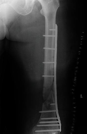
This anteroposterior (AP) view X-ray radiography of the left femur demonstrates internal fixation of a distal femoral fracture or nonunion. A long titanium locking compression plate (LCP) is positioned along the lateral aspect of the femoral shaft, extending from the proximal diaphysis to the distal metaphysis. The plate is secured with multiple radiopaque locking screws: five screws are visible in the proximal segment and five in the distal segment, bridging the fracture site. At the mid-to-distal transition of the femur, the fracture site exhibits signs of debridement with irregular bone margins and localized radiolucency, indicative of a bone defect or nonunion. This area is packed with autologous cancellous bone graft, visible as a cluster of mottled radiodense material within the surgical gap. The hardware appears intact, and the anatomical alignment of the femur is maintained. This image is clinically relevant for orthopaedic studies focusing on the management of complex femoral nonunions, bone grafting techniques, and the use of locking plate osteosynthesis.
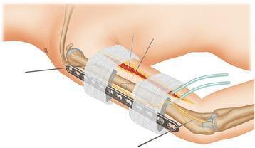
This orthopaedic schematic diagram illustrates the surgical application of a Locking Compression Plate (LCP) utilized as an external fixator for a humeral shaft fracture. The illustration depicts the humerus with a mid-shaft fracture being stabilized by a multi-hole LCP positioned along the lateral aspect of the arm. Key surgical details shown include the use of 2.0 mm Kirschner wires (K-wires) inserted through the most proximal and distal plate holes into the bone cortex for temporary fixation and alignment. A critical feature of the externalized plate technique is demonstrated by a stack of folded towel spacers placed between the plate and the skin surface, ensuring adequate clearance to accommodate soft tissue swelling while maintaining a parallel orientation to the long bone. The diagram also shows the proximity of anatomical structures, such as the radial nerve, and surgical components like drainage tubes and incision sites. This educational visual is intended for orthopaedic residents and surgeons to understand the stabilization logic of using an internal fixation plate in an external fixator configuration for managing complex or infected nonunions.
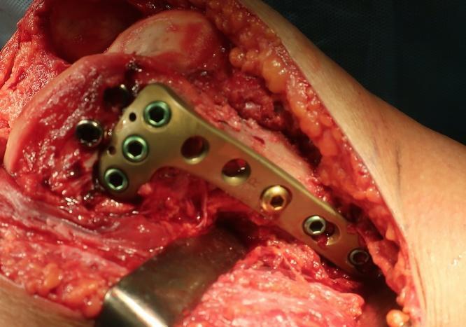
An intraoperative clinical photograph demonstrating an open reduction and internal fixation (ORIF) procedure for a distal femoral fracture. The image shows a locking compression plate (LCP) originally designed for the proximal tibia being utilized in an off-label, inverted orientation to provide anatomical fixation for the medial femoral condyle. The metallic plate is contoured to the bone surface and secured with a combination of cortical and locking screws. Key visible features include the exposed bone and soft tissue of the right knee joint through a medial parapatellar approach, with surgical retractors reflecting the tissue. The educational focus of this image is on unconventional hardware application and surgical salvage techniques for complex intra-articular fractures (AO classification: 33-B2.1). This material is relevant for orthopedic surgery residents and trauma surgeons specializing in lower limb reconstruction.
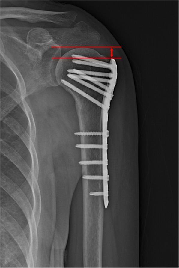
Anteroposterior (AP) x-ray of the shoulder demonstrating a proximal humerus fracture treated with internal fixation. A metallic locking compression plate (LCP) is positioned on the lateral aspect of the humeral shaft, extending superiorly to the greater tuberosity. The construct features multiple locking screws: proximal screws are oriented at varying angles to support the humeral head subchondral bone, while distal screws are inserted perpendicularly into the humeral diaphysis. Educational annotations in red illustrate the methodology for measuring Humeral Head Height (HHH). Two parallel horizontal lines are drawn: the superior line identifies the highest point of the humeral head articular surface, and the inferior line aligns with the top edge of the orthopedic plate. A double-headed vertical arrow indicates the distance between these lines, used clinically to monitor for postoperative loss of fixation or subsidence of the humeral head. The image provides a clear demonstration of orthopedic implant positioning and radiographic assessment parameters for proximal humeral fractures.
Locking Compression Plate (LCP)
Definition and Evolution
- Rockwood and Green's Fractures in Adults, 10th ed. 2025, p. 485
The Combi Hole - The Key Design Feature
- Dynamic compression unit (DCU) portion - an oval/oblong section where a standard cortical screw can be inserted eccentrically to generate interfragmentary compression (identical to a conventional DCP)
- Threaded locking portion - a threaded section where a locking head screw (LHS) engages and locks at a fixed angle
- Place cortical screws in the DCU portion to compress a fracture
- Place locking screws in the threaded portion for fixed-angle stability
- Use hybrid constructs combining both screw types
Biomechanical Principles
Conventional vs. Locking Screw
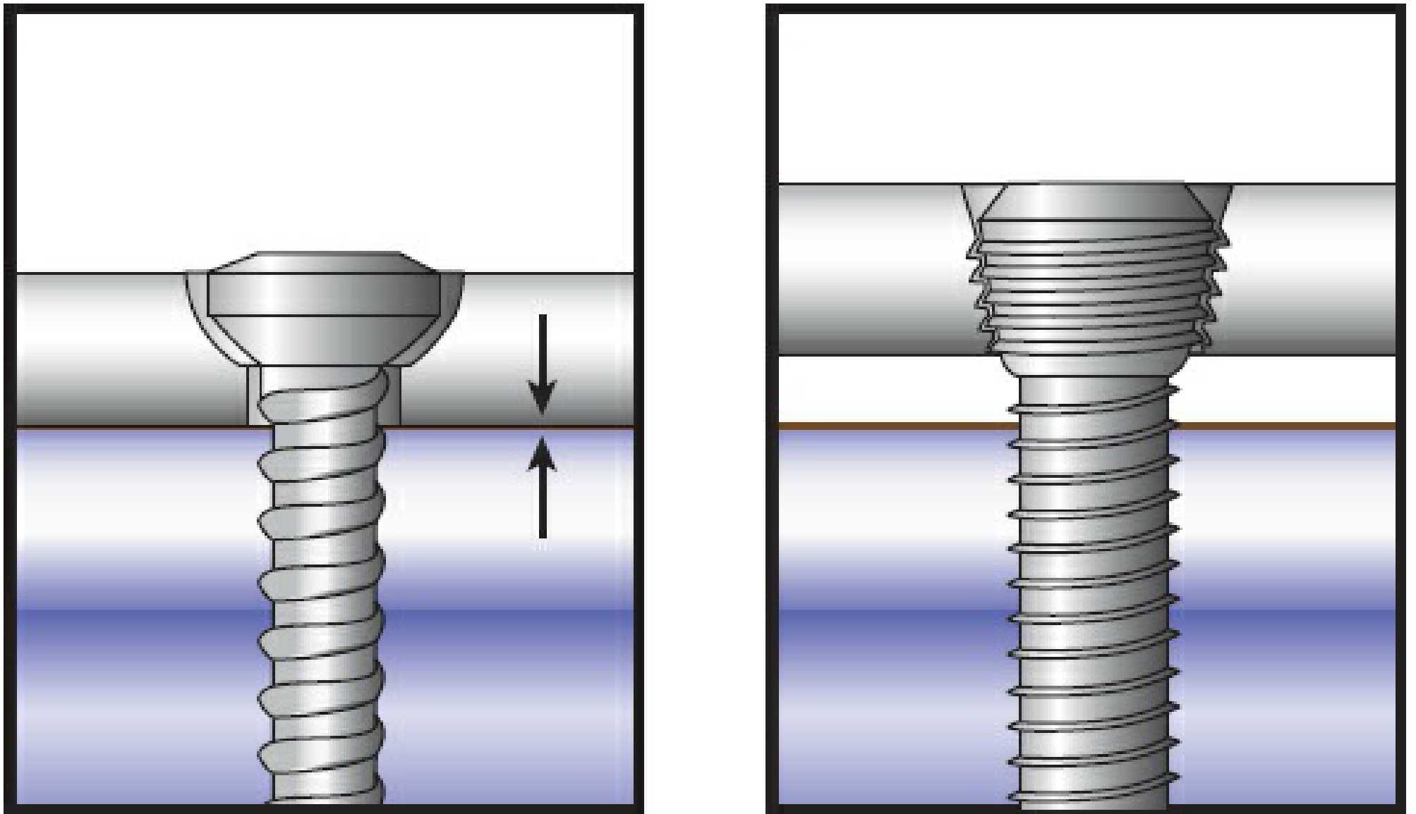
| Feature | Conventional Screw | Locking Screw |
|---|---|---|
| Screw head | Smooth | Threaded (matches plate hole threads) |
| Mechanism of stability | Plate-bone friction (requires preload/compression) | Fixed-angle construct (plate-screw interface) |
| Effect on bone | Draws bone to plate; can compress periosteum | Bone NOT pulled to plate; periosteum preserved |
| Core diameter | Smaller (relies on thread engagement) | Larger (resists bending forces) |
| Thread pitch | Standard | Finer pitch |
| Pull-out failure mode | Individual screw fails | All screws fail together (act in parallel) |
Force Transfer
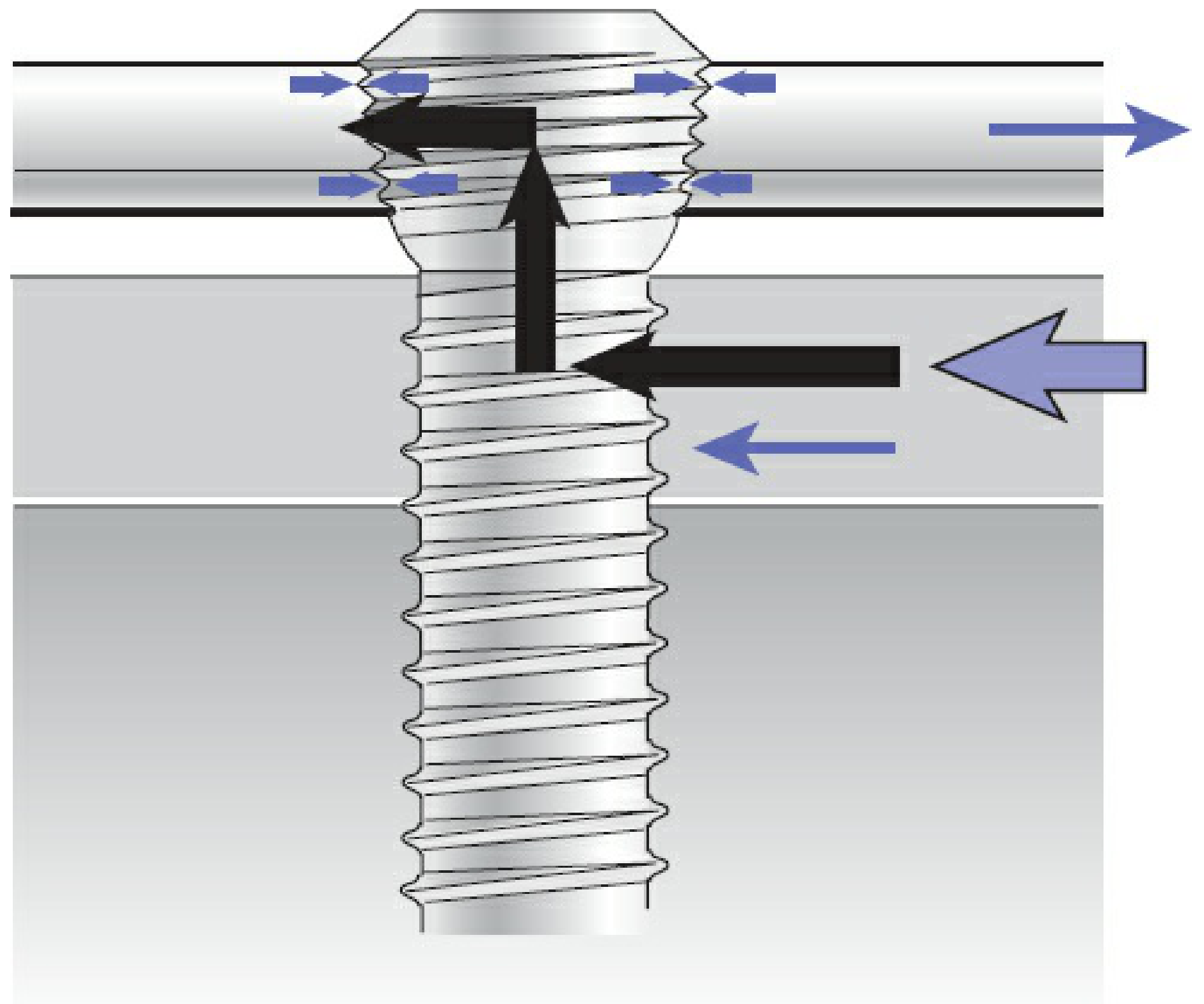
Advantages
- Osteoporotic bone - Fixed-angle construct does not depend on bone-plate friction; locking screws resist pull-out even in poor quality bone
- Short metaphyseal/periarticular segments - Multiple locking screws can be packed into a short distal/proximal segment (e.g., distal radius, distal femur, proximal humerus) where there is insufficient bone for conventional screw purchase
- Plate-bone mismatch - If the plate does not conform perfectly to the bone surface, locked screws will not disrupt an already-established anatomic reduction (conventional screws would draw the bone toward the plate, losing reduction)
- Biologic preservation - Reduced periosteal stripping and blood supply disruption because the plate need not be compressed against bone
- Bridge plating - Suitable for comminuted fractures managed with indirect reduction; acts as a relative stability construct stimulating callus formation
- Percutaneous insertion - Compatible with minimally invasive techniques using targeting jigs
Uniaxial vs. Polyaxial (Variable Angle) Locking
- Uniaxial locking: Single fixed angle per hole. Requires a threaded drill guide to ensure coaxiality with the plate hole (prevents cross-threading). More stable construct.
- Polyaxial (variable-angle) locking: Screws can lock at various trajectories. Uses a cone-shaped drill guide to stay within an acceptable angle range. More flexible placement options (e.g., directing screws around articular surfaces), but inherently less stable than uniaxial - though clinical significance is often minor.
Construct Design Principles
Plate Length and Screw Density
- A longer plate with fewer screws (lower screw density) increases the working length, which reduces stress concentration at the plate and encourages callus formation - ideal for bridge plating
- A shorter plate with more screws creates a stiffer construct - suitable for simple fractures with anatomic reduction and primary bone healing
- Minimum 2 screws per fragment for stability; many surgeons use 3 for safety
- Wider screw span within a fragment increases bending stiffness more than adding extra screws in the same span
- Torsional strength depends on the number of screws (not their location)
Bicortical vs. Unicortical Locking Screws
- Bicortical screws are significantly superior for resisting torsional stress
- Unicortical locking screws can be used in dense metaphyseal bone or to minimize soft tissue dissection
Hybrid Constructs
Critical Technical Principles (Pitfalls)
- Anatomic reduction BEFORE locking - A locked plate fixes the bone fragments in whatever position they are in when the locking screw is tightened. Unlike a conventional plate, it does NOT pull fragments into alignment. Reduction must be confirmed before ANY locking screw is placed.
- Locking screws are NOT lag screws - They do not generate compression across a fracture. Compression must be obtained separately using cortical screws in the DCU portion or via a reduction technique.
- Avoid excessive stiffness in bridge plating - An overly stiff locked construct used in bridge mode (no cortical contact) can produce inconsistent callus and premature peri-implant failure (plate breakage at the fracture gap).
- Screw angulation must be precise - Cross-threading a locking screw destroys the plate hole threads, permanently compromising that hole.
Common Clinical Applications
- Proximal humerus - 4-part fractures, osteoporotic bone, short proximal segment
- Distal radius - Volar locking plate for dorsally angulated fractures (Colles-type)
- Distal femur - Periarticular fixation, supracondylar fractures
- Proximal tibia - Tibial plateau fractures (LISS/LCP variants)
- Clavicle - Superior plating with locking screws has biomechanical advantages
- Humeral shaft - When intramedullary nailing is unsuitable
Clinical Images
- Rockwood and Green's Fractures in Adults, 10th ed. 2025 - Chapter 12 (Principles of Internal Fixation), pp. 474-495
- Campbell's Operative Orthopaedics, 15th ed. 2026
- Bailey and Love's Short Practice of Surgery, 28th ed.
- Synthes LCP System Technical Overview