
Write a short note on tripolar prosthesis for Ms orthopedics theory examination gold medal level
tripolar prosthesis hip arthroplasty orthopedics design mechanism advantages
tripolar hip prosthesis arthroplasty dislocation
https://pmc.ncbi.nlm.nih.gov/articles/PMC10929320
PMID: 38529131
tripolar hip prosthesis dual mobility total hip replacement diagram
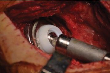
This clinical photograph provides an intraoperative in-situ view of a tripolar hip prosthesis during a revision total hip arthroplasty (THA). The image captures the surgical field of the hip joint, showing exposed soft tissue and muscle. The central focus is the novel Inovaris prosthesis assembly, which includes a metallic (cobalt-chrome) acetabular component with an visible inner locking rim. Seated within this shell is a white, high-molecular-weight polyethylene dual-mobility liner. A metallic femoral head is shown snapped into and secured within the liner. A cylindrical surgical instrument is currently engaged with the femoral head, likely for positioning or assessment of the component. The surrounding anatomy shows significant surgical disruption and raw tissue, characteristic of a direct lateral approach in a revision setting. This visual demonstrates the mechanical interface and containment mechanism of a constrained dual-mobility system designed to prevent dislocation and provide a wide range of motion.
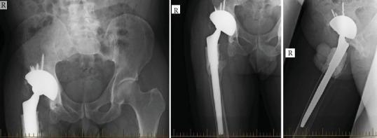
This composite of three diagnostic X-ray radiographs (anteroposterior, lateral, and oblique views) displays a right total hip arthroplasty (THA) following revision surgery. The imaging demonstrates a complex tripolar prosthesis designed for dual mobility and constraint. The acetabular component consists of a radiopaque multi-hole metallic shell securely fixed with several superiorly-directed orthopedic screws. A distinctive radiopaque mantle indicates that a revision liner has been cemented into the primary shell. The femoral component features a long, straight revision stem extending deep into the femoral shaft. A visible radiopaque halo surrounding the proximal femoral stem and within the acetabular interface is consistent with antibiotic-impregnated bone cement (PMMA) used for fixation and dead-space management. The femoral head is concentrically reduced within the dual-mobility liner. Clinically, this construct is utilized in complex revision cases involving gluteal deficiency, chronic instability, or periprosthetic infection to maximize range of motion while minimizing the risk of recurrent dislocation.
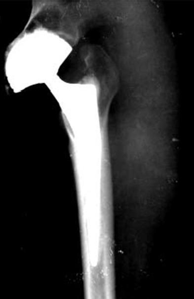
This diagnostic image is an anteroposterior (AP) X-ray radiograph of a human right hip following total hip arthroplasty (THA). The image demonstrates a well-positioned dual-mobility prosthesis. Key components include a radiopaque femoral stem securely seated within the medullary canal of the proximal femur and a large, hemispherical acetabular cup articulated with the femoral head. The femoral stem shows good cortical contact and integration. The acetabular component is appropriately inclined and positioned within the native acetabulum. Bony landmarks such as the greater trochanter and the pelvic rim appear stable, with no visible evidence of periprosthetic fracture, osteolysis, or implant loosening. This visual serves as an educational example of postoperative imaging for a dual-mobility hip replacement, frequently utilized in cases with high dislocation risk or muscular laxity to ensure joint stability.
Tripolar Prosthesis
Definition and Concept
Components and Architecture
- Femoral stem - standard cementless or cemented stem (identical to conventional THA)
- Bipolar head assembly (inner articulation) - a metal femoral head, typically titanium nitride (TiN)-coated (ceramic-coated in modern designs), sitting inside a polyethylene inner shell. This constitutes the inner bearing (small head-in-liner motion, ~28 mm head)
- Large-diameter acetabular component (outer articulation) - a hemispherical metal shell with a highly cross-linked polyethylene liner of large internal diameter (41-54 mm, median ~47 mm). The bipolar head unit articulates within this. This constitutes the outer bearing
Biomechanical Principles
Two Articulations, One Joint
- Inner articulation: femoral head rotates within the bipolar polyethylene shell
- Outer articulation: bipolar unit rotates within the large acetabular liner
Jump Distance
Head:Neck Ratio
Design Variants
| Type | Description | Key Feature |
|---|---|---|
| Unconstrained | Bipolar head is not locked into outer cup | Preferred; allows natural motion sharing |
| Constrained/Captured | Bipolar head locked into retentive outer liner | Greater theoretical stability but fails mechanically under stress; NOT recommended |
Constrained tripolar designs have been largely abandoned due to mechanical failure and high revision rates.
Comparison: Tripolar vs. Dual Mobility vs. Conventional THA
| Parameter | Conventional THA | Dual Mobility (DMC) | Tripolar |
|---|---|---|---|
| Bearing surfaces | 1 | 2 | 2 |
| Effective head diameter | 28-36 mm | 28-36 mm (large outer cup) | ~47 mm |
| Dislocation risk | Higher | Low | Lowest (unconstrained) |
| ROM | Moderate | High | Near-normal (145° combined flex/ext) |
| Intraprosthetic dislocation | Not applicable | Risk present | Minimal (bipolar separation force ~2,180 N) |
| Volumetric wear | ~38 mm³/yr (40 mm head) | ~54 mm³/yr | ~24 mm³/yr (lowest) |
| Osteolysis | Present | Present | None documented in retrieval studies |
Indications
- Revision THA for recurrent dislocation - the primary indication
- High-demand young active patients (adventure sports, physically demanding occupations)
- Patients requiring unrestricted postoperative ROM (no activity restrictions)
- Neuromuscular disorders with abductor weakness (Parkinson's, cerebral palsy)
- Conversion of failed bipolar hemiarthroplasty with acetabular wear
- Femoral failure after polyethylene hip resurfacing
- Any patient where surgeon would otherwise use a constrained liner
Surgical Technique Highlights
- Can be performed via any standard approach (anterior, anterolateral, posterior)
- A conventional THA can be upgraded to tripolar simply by:
- Adding a bipolar component over the existing femoral head
- Replacing the polyethylene acetabular liner with a larger-diameter one
- The shell and stem remain unchanged
- Minimally invasive/robotic-assisted techniques are compatible
- Direct anterior approach (DAA) is commonly used in modern practice
Outcomes and Evidence
- Mean UCLA activity score: 7.9 (high activity)
- Combined flexion/extension arc: 145° (vs. 119° for conventional THA)
- No osteolysis on radiographs
- No intraprosthetic dislocation
- Bipolar separation force: 2,180 N (versus ~340 N generated by high-demand activity - a safety margin of 6.4x)
- Implant survivorship supporting lifetime use even in highest-demand patients
- Patient-reported outcomes, sexual, and functional scores were higher than conventional THA
- Full unrestricted activity was permitted postoperatively
- No postoperative dislocation restrictions required
Advantages
- Lowest dislocation rate of any unconstrained THA construct
- Near-normal ROM without activity restrictions
- Lowest wear - below the osteolytic threshold (~24 mm³/yr)
- No intraprosthetic dislocation risk (unlike dual mobility cups)
- No metal-on-metal wear reaction
- Limited acetabular stress shielding
- Can convert existing THA to tripolar without stem/shell revision
- Compatible with all standard surgical approaches
Disadvantages and Complications
- Not widely used - limited long-term multi-centre data
- More complex construct than conventional THA
- Requires larger acetabular shell to accommodate the large-diameter bipolar unit
- Constrained designs (now obsolete) had high mechanical failure rates
- Potentially higher polyethylene debris volume (though wear rate is actually low per retrieval data)
- Increased operative complexity in index procedure
Relevant Image
Key Exam Points (Gold Medal Tips)
- The term "tripolar" refers to three poles of articulation: inner head, inner cup surface, outer cup surface
- The fundamental difference from a dual mobility cup: in DMC the small femoral head articulates inside a large mobile liner which in turn sits in the metal shell; in tripolar, a full bipolar prosthesis (its own separate articulating unit) is used as the inner bearing inside the outer cup
- Jump distance formula: proportional to femoral head diameter - tripolar achieves highest jump distance of all unconstrained designs
- Wear is paradoxically lower in tripolar than in conventional large-head THA because motion is shared across two surfaces, reducing excursion at each interface
- Constrained tripolar = mechanical failure; unconstrained tripolar = preferred design
- Primary indication in exams: recurrent post-THA dislocation and revision surgery
- Pritchett JW. Wear and performance of a tripolar total hip replacement. Ann Jt. 2022. PMID 38529131
- Pritchett JW. Adventure sports and sexual freedom hip replacement: the tripolar hip. EFORT Open Rev. 2017
What is the difference of implant design compared to conventional thr
Implant Design: Tripolar vs. Conventional THR
Conventional THR - Basic Architecture
Femoral Stem → Femoral Head → Polyethylene Liner → Metal Acetabular Shell
                    ↑
           Single articulation here
- Femoral head (28-36 mm) articulates directly against a fixed polyethylene liner
- The liner is locked into the acetabular shell and does not move
- Motion occurs at one point only - the head-liner interface
Tripolar THR - Architecture
Femoral Stem → Femoral Head → Bipolar Inner Shell → Large Poly Liner → Metal Acetabular Shell
                    ↑                    ↑
           Inner articulation    Outer articulation
- The femoral head (28 mm) rotates inside a polyethylene bipolar inner shell
- That entire bipolar unit (now ~47 mm effective diameter) rotates inside a large-diameter fixed polyethylene liner
- Motion is shared across two surfaces
Component-by-Component Comparison
| Component | Conventional THR | Tripolar THR |
|---|---|---|
| Femoral stem | Standard (cemented or cementless) | Identical - no difference |
| Femoral head | 28-36 mm metal/ceramic | 28 mm metal, TiN/ceramic-coated |
| Inner bearing unit | None | Bipolar prosthesis (head sits inside poly inner shell) |
| Acetabular liner | Fixed UHMWPE, 28-36 mm inner diameter | Large HXLPE, 41-54 mm inner diameter |
| Acetabular shell | Standard hemispherical shell | Larger diameter shell to accommodate bipolar unit |
| Number of articulations | 1 | 2 |
| Effective head diameter | 28-36 mm | ~47 mm (bipolar unit outer diameter) |
The Critical Design Difference - Visually
[Stem]---[Head 28-36mm]<<<articulates against>>>[Fixed Liner]---[Shell]
- 1 moving interface
- Head is a solid ball against a fixed cup
[Stem]---[Head 28mm]<<<inner>>>[ Bipolar Shell ]<<<outer>>>[Large Liner]---[Shell]
         ↑ Inner articulation ↑              ↑ Outer articulation ↑
- 2 moving interfaces
- The bipolar shell floats between the head and the outer cup
- The head never directly contacts the outer liner
Design Consequences - Why It Matters
- Conventional 32 mm head: jump distance ~11 mm
- Conventional 36 mm head: jump distance ~12 mm
- Tripolar (~47 mm effective): jump distance ~16 mm
- Jump distance = the displacement needed to dislocate; larger = more stable
- In conventional THR, the neck can impinge against the liner rim at ~120° ROM
- In tripolar, the neck impinges against the inner bipolar rim first; the outer large cup is recessed and almost never reached
- Net effect: impingement-free arc is greatly extended
- Conventional: all wear concentrated at one surface
- Tripolar: wear distributed across two surfaces, each operating through smaller excursion angles
- Result: lower total volumetric wear (~24 mm³/yr vs ~38 mm³/yr for conventional 40 mm head)
- Conventional THR: combined flex/extension ~119°
- Tripolar: combined flex/extension ~145°
- Near-normal physiological ROM without risk of dislocation
What is Shared (No Design Difference)
- The femoral stem is identical to any standard cementless/cemented THA stem
- The acetabular metal shell outer geometry is the same (hemispherical, porous-coated for ingrowth)
- Fixation philosophy (cementless ingrowth, cemented) is unchanged
- Surgical approaches are the same - any standard approach works
Conversion Point (Exam Favourite)
- Keep the existing femoral stem
- Keep the existing acetabular metal shell
- Swap the fixed liner for a larger-diameter HXLPE liner
- Add a bipolar head assembly over the existing femoral head
Write a short note on functional braces in ortho
functional braces orthopedics types mechanism indications Sarmiento brace fracture bracing
functional bracing fractures orthopedic outcomes
functional brace Sarmiento humerus tibial fracture bracing
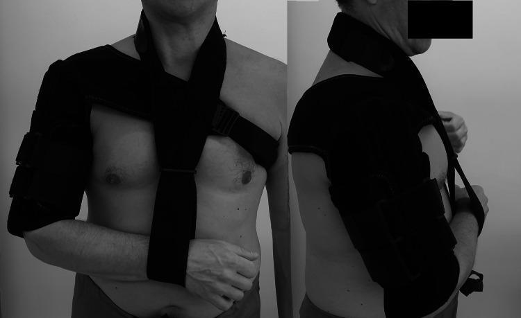
Clinical photograph (anterior and lateral views) showing a prefabricated humeral functional brace (Clasby Humeral Brace) applied to a patient's right upper extremity. The device is a dark, semi-rigid orthosis designed for the conservative management of humerus midshaft fractures. The humeral shell extends from the acromion to just proximal to the elbow crease, composed of overlapping panels secured by circumferential velcro straps to provide soft tissue compression. The suspension system features a wide strap originating from the humeral component, crossing diagonally over the contralateral shoulder, and a secondary stabilization strap crossing the anterior chest. A distal wrist cuff is integrated to support the forearm in a neutral position. This orthosis facilitates fracture stabilization through the principle of hydrostatic compression of the surrounding musculature while allowing motion at the shoulder and elbow joints to prevent stiffness. It is specifically used in orthopedic trauma for patients where surgical intervention is not indicated or as a follow-up to initial coaptation splinting.
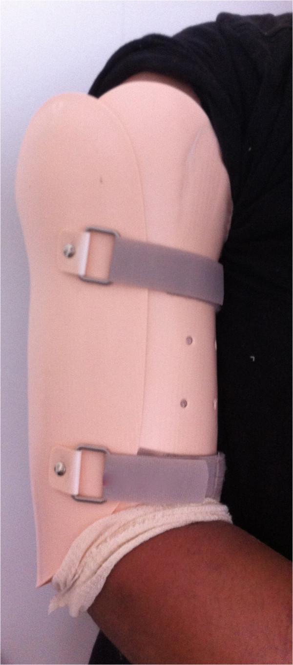
This clinical photograph shows a functional humeral brace, also known as a Sarmiento brace, applied to the upper arm of a patient. The brace is a rigid, pink-toned thermoplastic orthosis designed to provide circumferential compression of the arm while allowing for range of motion at the shoulder and elbow joints. The orthosis features a contoured proximal edge that extends toward the deltoid region and is secured by two grey adjustable straps with metal D-ring fasteners and rivets. Multiple small ventilation holes are visible on the lateral aspect of the shell to promote airflow. Beige soft padding is visible at the distal margin near the elbow to protect the skin and improve patient comfort. This type of device is typically used for the conservative management of humeral shaft fractures, utilizing the principle of soft tissue compression to stabilize the fracture site during the consolidation phase.
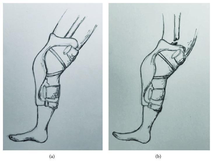
This medical illustration depicts the proposed mechanism of injury for a femoral shaft fracture associated with a rigid knee brace. Panel (a) shows a lower extremity wearing a hard-shell, hinged knee brace in terminal extension. The brace is secured with proximal thigh and distal tibial straps, stabilizing the knee joint. As an extension moment is applied, the rigid proximal edge of the brace acts as a fulcrum against the femur. Panel (b) illustrates the resultant pathology: as hyperextension force exceeds the bone's structural integrity, a transverse fracture occurs in the femoral shaft at the proximal edge of the brace. This diagram highlights the 'stress riser' effect where rigid orthotic equipment can unintentionally transfer forces to adjacent long bones, leading to a cantilever bending injury similar to a 'boot top fracture.' The illustration is intended for orthopedic education, specifically regarding trauma mechanisms in sports medicine and the biomechanical risks of prophylactic bracing in high-impact activities.
Functional Braces in Orthopaedics
Definition
Biological and Biomechanical Rationale
1. Hydraulic Pressure Principle
2. Motion-Stimulated Healing
3. Muscle Pump Effect
Types of Functional Braces
A. Fracture Functional Braces
| Type | Description |
|---|---|
| Humeral shaft brace (Sarmiento brace) | Two plastic/thermoplastic sleeves (medial-lateral or anterior-posterior) held by adjustable Velcro straps; extends from axilla to proximal to elbow crease |
| Tibial functional brace / PTB brace | Patellar tendon-bearing design; extends from below knee to above ankle; allows ankle and knee motion |
| Custom-fabricated brace | Thermoplastic material moulded to the individual limb; adjustable as swelling reduces |
| Prefabricated (off-the-shelf) brace | Standard sizes (e.g. Clasby humeral brace); less customizable but widely available |
B. Ligamentous / Joint Functional Braces
| Type | Use |
|---|---|
| Prophylactic knee brace | Prevents ligament injury in contact sports |
| Functional/rehabilitative ACL brace | Protects healing ACL graft; controls rotation and anteroposterior translation |
| Hinged knee brace | Post-collateral ligament injury; allows flexion-extension while limiting valgus/varus |
| Ankle-foot orthosis (AFO) | Controls ankle position in neuromuscular conditions |
| TLSO (Thoracolumbar spinal orthosis) | Controls spinal fractures, scoliosis; permits upright activity |
Specific Applications
1. Humeral Shaft Fractures - The Gold Standard Use
- Initial 7-10 days: temporary immobilization (coaptation splint / U-slab / hanging cast) to allow oedema to subside
- Transition to functional brace once acute swelling settles
- Brace: two plastic shells (anterior-posterior or medial-lateral) secured with Velcro; applies compressive pressure to muscle belly
- Patient wears collar-and-cuff sling; elbow motion encouraged daily to prevent stiffness
- Pendulum shoulder exercises commenced immediately
- Patient taught to tighten Velcro straps as swelling subsides
- Up to 20° anterior/posterior angulation
- Up to 15° varus angulation
- Rotation is difficult to control - a key limitation
- Nonunion rate: 2.6% (1.5% closed, 5.8% open fractures)
- Average healing time: 9.5 weeks (closed), 14 weeks (open)
- 88.6% lost <10° shoulder motion; 92% lost <10° elbow motion
- Overall healing: ~93.5% across published series (Rockwood & Green, 10th ed, 2025)
- Average time to union across series: 10.7 weeks
2. Tibial Shaft Fractures
- Initial long-leg cast or well-moulded splint for 2-4 weeks (until swelling settles and callus begins)
- Transition to short-leg PTB (patellar tendon-bearing) cast or fabricated functional brace
- Advantage over PTB cast: allows both ankle and knee motion simultaneously
- Early weight-bearing is mandatory - it drives fracture healing through functional loading
- Open fractures (Grade II/III) - soft tissue damage prevents adequate circumferential compression and monitoring
- Initial shortening >12 mm (not correctable by bracing)
- Tibial fracture with intact fibula (increased risk of late varus angulation from fibular tether effect)
- Ipsilateral injuries preventing weight-bearing
- Fractures with initial displacement >30-50%
- Nonunion: 1.1%
- 94% healed with shortening ≤12 mm
- 90% healed with angulation ≤6°
- Average shortening at final follow-up: 4.3 mm (not significantly worsened by bracing/weight-bearing)
3. Ulnar Shaft Fractures (Nightstick Fracture)
- Functional bracing is highly effective for isolated ulnar shaft fractures
- Sarmiento reported 96.5% good and excellent results in the largest published series
- Significant advantage: preserves forearm rotation and prevents disuse atrophy
4. Knee Ligament Injuries / Post-operative Rehabilitation
- Functional braces are used after ACL reconstruction, collateral ligament repair, and meniscal surgery
- They provide proprioceptive feedback, protect the healing graft from valgus/varus/rotational stress, and allow progressive ROM
- Surgical textbooks (Schwartz's Principles of Surgery, 11th ed) recommend a functional brace for sports return after collateral ligament healing
5. Vertebral Compression Fractures / Spinal Fractures
- TLSO braces are a conservative option for stable thoracolumbar fractures
- Allow upright activity while offloading the anterior column
Indications Summary
| Fracture | Recommendation |
|---|---|
| Humeral shaft (closed, AO Type A, long oblique, spiral) | Functional bracing - treatment of choice |
| Isolated ulnar shaft (nightstick) | Functional bracing - excellent results |
| Tibial shaft (closed, low-energy, minimal shortening) | Functional bracing - valid option |
| Periprosthetic fracture (distal to stem, stable) | Functional bracing reported in selected cases |
| Open fractures (Grade I selected) | Sarmiento reported success, but most centres prefer operative fixation |
| Femur shaft | Generally not suitable - inadequate soft tissue sleeve |
Contraindications
- Fractures with unacceptable initial alignment not correctible by closed means
- Open fractures Grade II and above
- Polytrauma where patient requires crutches (tibia) - weight-bearing impossible
- Ipsilateral upper extremity fractures requiring crutch use (humerus)
- Initial fracture shortening beyond acceptable limits
- Intact fibula with tibial fracture (tether effect - varus risk)
- Segmental fractures with significant displacement (relative)
- Non-compliant patients
Advantages Over Plaster Cast
| Advantage | Mechanism |
|---|---|
| Preserves adjacent joint motion | Brace does not cross the joint |
| Prevents muscle atrophy | Active muscle contraction permitted |
| Allows soft tissue monitoring | Brace is removable |
| Adjustable as swelling resolves | Velcro straps tighten/loosen |
| Promotes callus formation | Micro-motion stimulates healing |
| Better functional recovery | Early rehabilitation possible |
| No need for serial cast changes | Brace adjustment suffices |
Complications
- Varus angulation - particularly in transverse humeral fractures; caused by gravity on the unsupported elbow/arm
- Rotational malunion of shoulder - loss of external rotation in up to 38-45% (under-recognized)
- Nonunion - especially transverse fractures of the humerus (up to 9% in some series) and open tibial fractures
- Skin problems - pressure sores, skin breakdown at plastic edges
- Malunion - 32% in tibial closed treatment (systematic review data)
- Brace loosening - as oedema resolves; requires patient compliance in tightening
Key Exam Points
- Sarmiento described functional humeral bracing in 1977 and tibial bracing in the 1960s
- Mechanism = hydraulic pressure of soft tissue sleeve + motion-stimulated callus
- The brace does NOT rigidly immobilize - it controls alignment while permitting functional activity
- For humerus: acceptable deformity = 20° anterior/posterior, 15° varus; valgus and rotation are less well controlled
- For tibia: intact fibula is a relative contraindication (varus tendency)
- Nonunion rates: humerus 2.6% (Sarmiento), tibia 1.1% (Sarmiento) - but other series show higher rates
- The major competitor for tibial fractures is IM nailing - RCTs and meta-analyses favour nail fixation over functional bracing for most tibial shaft fractures
- For isolated ulnar shaft fractures: 96.5% good/excellent - functional bracing is particularly effective here
- Rockwood and Green's Fractures in Adults, 10th ed (2025) - Chapters on Humeral Shaft and Tibial Shaft Fractures
- Campbell's Operative Orthopaedics, 15th ed (2026)
- Sarmiento A et al. - Humeral shaft functional bracing, JSES 2002 (PMID 11988725)
- Fox HM et al. Humeral shaft cost-effectiveness analysis, J Shoulder Elbow Surg 2022 (PMID 35398163)