
Extended trochanteric osteotomy ms ortho 20 marks answer
Reading File
Now let me search the medical library and web simultaneously for comprehensive information on Extended Trochanteric Osteotomy.
Finding Sources
Finding Sources
Searching the Web
extended trochanteric osteotomy technique indications complications orthopedic surgery
Excellent! Found content in Campbell's. Let me read the relevant sections.
Reading File
Reading File
Reading File
Let me read more of the ETO technique and get the figures.
Reading File
Reading File
Loading Image
Let me fetch the key ETO technique diagram and read more about complications and fixation.
Loading Image
Reading File
Reading File
I now have comprehensive material from Campbell's Operative Orthopaedics. Let me also fetch the radiographic figure and get info on complications/outcomes.
Loading Image
Finding Sources
I have all the key content from Campbell's. Now I'll write the comprehensive 20-mark MS Ortho answer.
Extended Trochanteric Osteotomy (ETO)
MS Orthopaedics - 20 Marks Answer
Definition
Extended Trochanteric Osteotomy (ETO) is a proximal femoral osteotomy in which a segment of the lateral femoral cortex of variable length is raised in continuity with the greater trochanter, thereby providing direct access to the femoral canal and acetabulum. It was originally described by Younger et al. and has become the most useful approach in revision total hip arthroplasty (THA).
Anatomy of the Osteotomy Fragment
The osteotomized fragment comprises approximately one-third of the circumference of the proximal femur (the lateral wall), consisting of:
- The greater trochanter with attached gluteus medius and minimus (abductors)
- The lateral femoral cortex extending distally (variable length, typically 10-15 cm)
- The origin of vastus lateralis distally (sleeve of tissue maintained)
This creates a hinged segment that swings anteriorly, exposing the prosthesis laterally while maintaining anterior soft-tissue attachments.
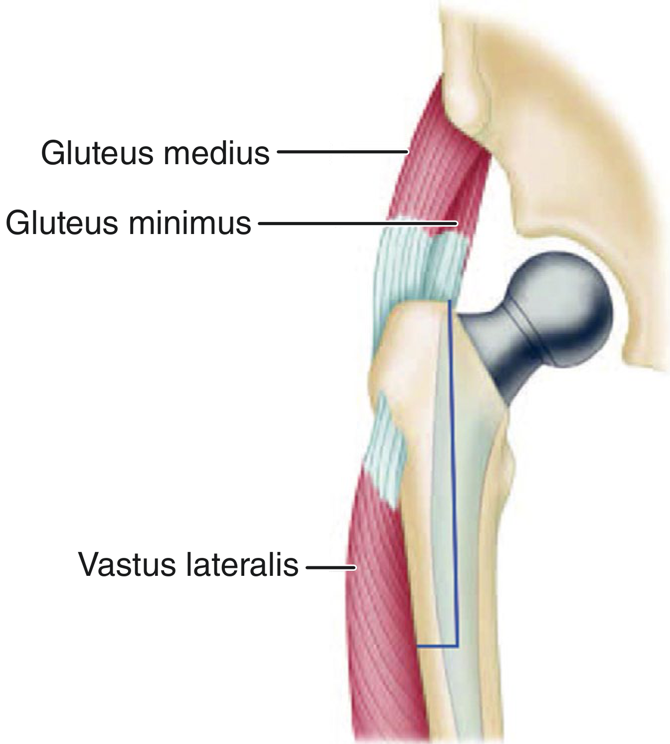
Comparison with Other Trochanteric Osteotomies
Three types are used in hip arthroplasty (Campbell's, p. 279):
| Feature | Standard Osteotomy | Trochanteric Slide | ETO |
|---|---|---|---|
| Fragment | Greater trochanter only | GT + vastus lateralis origin | GT + lateral femoral cortex |
| Exposure | Acetabulum (superior) | Acetabulum + femoral canal | Full femoral canal |
| Main use | Complex acetabular revision | Primary/revision THA | Revision with well-fixed stems |
| Fixation | Wires | Wires/cables | Multiple cerclage cables |
Indications
Primary Indication: Revision Total Hip Arthroplasty when:
- Well-fixed cemented or cementless femoral component that cannot be removed by conventional means
- Cement mantle extending to diaphysis - to allow safe removal under direct vision
- Broken/fractured femoral stem - distal fragment inaccessible from above
- Severe femoral deformity - bowing, angular deformity, or previous osteotomy preventing standard reaming
- Periprosthetic joint infection - when complete cement/implant removal is mandatory
- Marked femoral osteolysis - with cortical thinning at risk of iatrogenic fracture
- Significant limb length discrepancy - distal translation of fragment allows abductor tensioning
- Extensive heterotopic ossification - requiring wide surgical access
- Failed prior standard trochanteric osteotomy - nonunion with distorted anatomy
- Severe protrusio acetabuli - extensile acetabular exposure needed
Note: ETO is most appropriately used when a cementless femoral revision is planned, because cement intrusion into the osteotomy site may inhibit union. (Campbell's, p. 338)
Preoperative Planning
- Full-length AP and lateral radiographs of the femur
- Templating to determine osteotomy length: distal extent must be 5-6 cm proximal to the femoral isthmus to allow 5-6 cm of cortical contact for the revision stem
- CT scan to assess bone stock and cement extent
- Plan for revision stem length - stem must bypass the distal osteotomy by at least 2 cortical diameters (~5 cm)
- Cerclage cables and strut allografts prepared
Surgical Technique (Younger et al. - Technique 4.15, Campbell's)
Approach: Posterolateral (standard), with the patient in lateral decubitus.
Step-by-Step:
-
Mark osteotomy length so the distal extent of the well-fixed prosthesis is maximally exposed, leaving 5-6 cm of femoral isthmus intact for endosteal contact by the revision stem (Fig. 4.146)
-
Expose the hip via posterolateral approach with circumferential exposure of both implants
-
Protect the sciatic nerve throughout the entire procedure
-
Dislocate the hip - or perform osteotomy before dislocation if complicated by stem subsidence, acetabular protrusion, or hip stiffness
-
Position the thigh in internal rotation
-
Incise the vastus lateralis along its posterior edge to the level of the distal extent of the planned osteotomy
-
Mark the osteotomy longitudinally just lateral to the linea aspera, extending distally to the level determined by preoperative radiographs (Fig. 4.147A)
-
Create posterior cortex osteotomy: Using a thin high-speed burr, make multiple perforations in the posterior femoral cortex and connect them, skirting the lateral edge of the underlying femoral component
-
Transverse distal cut: Divide the lateral cortex transversely at the predetermined distal level
-
Anterior cortex perforations: Perforate the anterior cortex at multiple sites, creating a fragment of approximately one-third the circumference of the femur; leave as much vastus lateralis attached to the fragment as possible
-
Divide the superior anterior cortex with an oscillating saw (the burr may not be long enough in the trochanteric region)
-
Controlled fracture: Insert two or more broad osteotomes into the posterior limb and lever from posterior to anterior, creating a controlled fracture through the perforated anterior cortex while leaving anterior soft-tissue attachments undisturbed (Fig. 4.147B)
-
Reflect fragment anteriorly - lateral surface of femoral component is now visible; remove cement from interfaces under direct vision to allow stem extraction
-
For well-fixed cementless stem: Pass a Gigli saw beneath the collar directed distally, following the medial edge of the component (Fig. 4.147C); divide the interface to the distal extent of porous surface
-
Alternative: Shorten the osteotomy and divide the femoral component with a metal-cutting burr at the junction of triangular and cylindrical portions; remove distal segment with a trephine reamer
-
Prophylactic cerclage: Place a cable/wire around the femoral shaft distal to the osteotomy to prevent fracture propagation
-
Revision stem placement: Ream the diaphysis and impact the revision stem
-
Repair the osteotomy: Multiple cerclage cables; shape the undersurface of the fragment to fit the revision prosthesis; advance distally if needed for abductor tensioning
-
Reinforce if thin: If the fragment is thin and fragile, reinforce with a cortical allograft strut
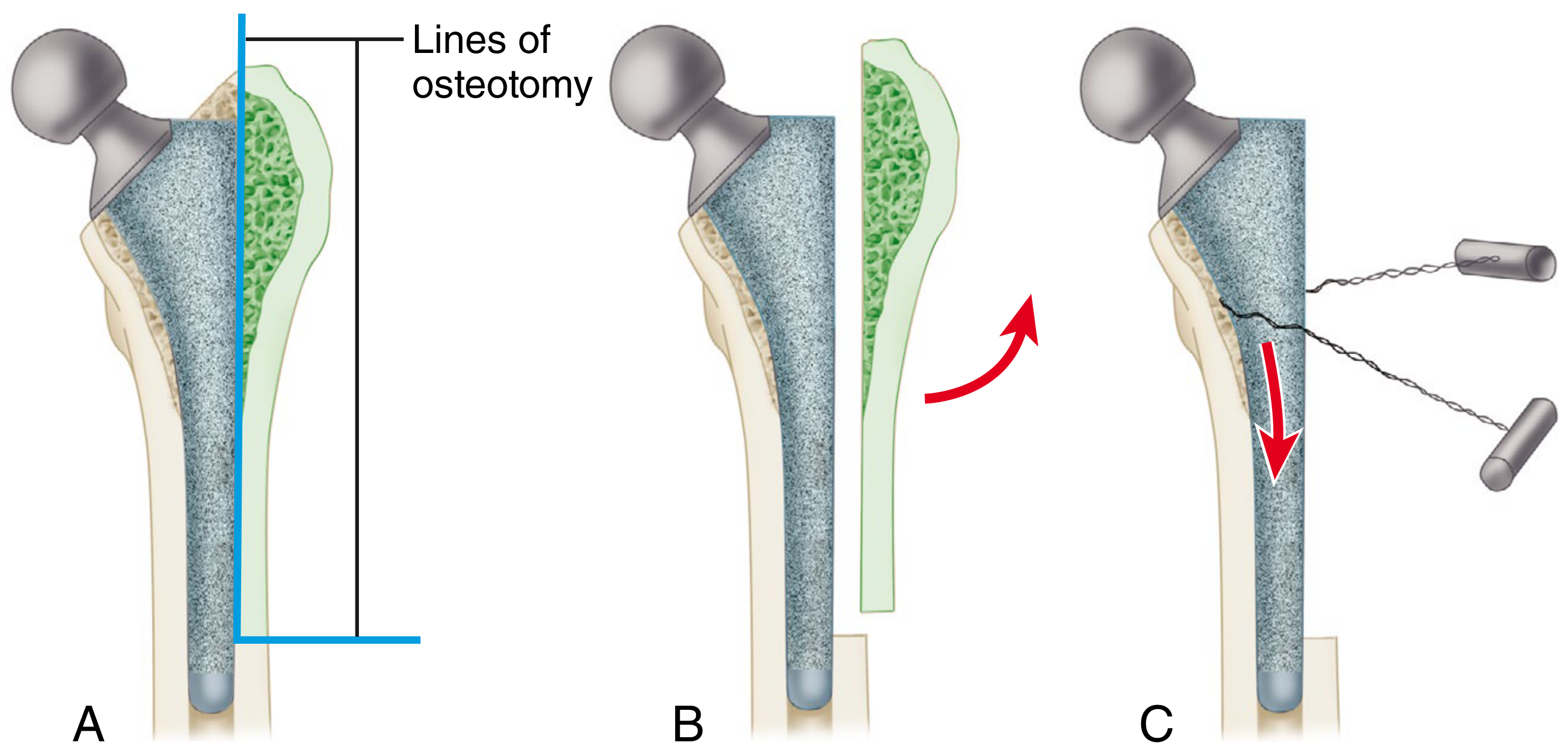
Fragment Fixation Methods
The lateral fragment must be held reduced with rigid fixation to allow union:
- Multiple cerclage cables (most common) - 2 to 4 cables around the fragment and shaft; cables provide circumferential compression
- Cable-plate systems (e.g., Accord trochanteric fixation plate) - proximal hooks capture the trochanteric fragment; plate extension is fixed to femur with cerclage cables; provides better resistance to shear and proximal migration
- Cortical allograft struts - used when the fragment is thin/osteopenic; placed on the lateral cortex and secured with cables; augments fixation and provides biological advantage
Key fixation principles:
- The hip should not be abducted more than 10-15 degrees during reattachment (excess strain leads to avulsion/nonunion)
- Anatomic reduction or slight distal overlap leads to union within 6 months
- Fragment with superior/medial tilt invariably leads to delayed union or nonunion
- Compression across the osteotomy is required for union
Postoperative Care
- Weight bearing: Toe-touch or partial weight bearing for 8-12 weeks
- Hip precautions: Abduction brace in some patients; avoid extreme flexion and adduction
- Physiotherapy: Graduated abductor strengthening once radiographic callus is evident
- Serial radiographs at 6 weeks, 3 months, 6 months to assess union
- Full weight bearing typically at 3 months if union is progressing
Outcomes
- Union rate: Meta-analysis reports 93% union rate with ETO (Campbell's, p. 338)
- Stem subsidence >5 mm: Reported in 7% with this technique
- Dislocation rate: ~3.7% (systematic review data; higher - up to 5% - in periprosthetic fracture cases)
- Aseptic loosening: ~1% (higher in periprosthetic fracture cases)
- Better outcomes with cementless reconstruction vs. cemented revision
Complications
Intraoperative
- Uncontrolled fracture propagation distally - prevented by prophylactic cerclage cable below osteotomy
- Sciatic nerve injury - must be protected throughout; especially at risk with limb lengthening
- Vascular injury - superficial femoral artery at risk during cable passage
- Fragment comminution - especially in osteoporotic bone
Early Postoperative
- Dislocation - higher risk due to abductor disruption; rate ~3.7%
- Infection - increased operative time and blood loss increase risk
- Fragment displacement/proximal migration - if fixation fails
Late
- Trochanteric nonunion - most important complication; reported up to 20% in some series; results in:
- Trendelenburg gait
- Abductor weakness and hip instability
- Pain and reduced function
- Cerclage wire/cable breakage - common even with solid union; usually not clinically significant
- Stem subsidence - particularly if cement intrudes into osteotomy; occurs in ~7%
- Heterotopic ossification - consider prophylaxis in high-risk patients
- Femoral component loosening - rare (~1%)
- Trochanteric bursitis - from prominent hardware
Contraindications (Relative)
- Planned cemented femoral reconstruction (cement prevents osteotomy union)
- Severe osteoporosis where fragment too fragile to hold fixation
- Active deep infection without plan for thorough debridement
Modified Techniques
- Lakstein modification: Posterior capsule and short external rotators left intact to reduce dislocation risk
- Wagner (anteriorly-based) osteotomy: Anteriorly based rather than laterally based; used when the lateral cortex is thin or compromised
- Paprosky (laterally-based) osteotomy: Standard ETO as described above; most widely used
Key Points for Examination
| Point | Detail |
|---|---|
| Originally described by | Younger et al. |
| Fragment size | ~1/3 circumference of femur laterally |
| Fragment length | Exposes distal extent of prosthesis; isthmus intact for 5-6 cm |
| Approach | Posterolateral |
| Preferred reconstruction | Cementless (cement inhibits union) |
| Fixation | Multiple cerclage cables ± cable plate ± strut allograft |
| Union rate | 93% (meta-analysis) |
| Stem subsidence | 7% |
| Dislocation rate | 3.7% |
| Key complication | Trochanteric nonunion - Trendelenburg gait |
Source: Campbell's Operative Orthopaedics 15th Ed (2026), Techniques 4.15, pp. 335-340; PMC review on trochanteric osteotomy variants (PMC7484712); IntechOpen ETO chapter.
Extended trochanteric osteotomy ms ortho 20 marks answer
I already have comprehensive textbook content from Campbell's Operative Orthopaedics (15th Ed) from your previous question. Here is the complete 20-mark MS Ortho answer:
Extended Trochanteric Osteotomy (ETO)
Definition
Extended Trochanteric Osteotomy (ETO) is a proximal femoral osteotomy in which a segment of the lateral femoral cortex of variable length is raised in continuity with the greater trochanter, providing direct access to the femoral canal and acetabulum. First described by Younger et al., it is the most valuable technique in revision total hip arthroplasty (THA).
Anatomy of the Fragment
The osteotomized fragment comprises approximately one-third the circumference of the proximal femur (lateral wall), consisting of:
- Greater trochanter with attached gluteus medius and minimus (abductors) proximally
- Lateral femoral cortex extending distally (variable length, typically 10-15 cm)
- Origin of vastus lateralis distally - preserved to prevent proximal migration
The fragment hinges anteriorly on intact anterior soft tissues, exposing the entire lateral surface of the prosthesis while maintaining the musculotendinous sleeve.
Types of Trochanteric Osteotomy - Comparison
Three basic types are used in hip arthroplasty (Campbell's, p. 279):
| Feature | Standard | Trochanteric Slide | ETO |
|---|---|---|---|
| Fragment | GT only | GT + vastus origin | GT + lateral cortex |
| Exposure | Acetabulum | Acetabulum + canal | Full femoral canal |
| Main use | Complex acetabular revision | Primary/revision THA | Revision with fixed stems |
| Fixation | Wires | Wires/cables | Cerclage cables |
Indications
Primary use: Revision THA where standard techniques are insufficient.
- Well-fixed cemented femoral component with cement extending to diaphysis - allows removal under direct vision
- Well-fixed cementless femoral component that cannot be removed conventionally
- Broken/fractured femoral stem - distal fragment inaccessible from above
- Severe femoral deformity - bowing, angular deformity, or previous femoral osteotomy
- Periprosthetic joint infection - complete implant and cement removal mandatory
- Extensive femoral osteolysis - cortical thinning with risk of iatrogenic fracture during extraction
- Significant limb length discrepancy - distal translation of fragment allows precise abductor tensioning
- Extensive heterotopic ossification requiring wide access
- Failed prior trochanteric osteotomy with nonunion and distorted anatomy
- Severe protrusio acetabuli requiring extensile acetabular exposure
Important: ETO is most appropriately used when a cementless femoral revision is planned, because cement intrusion into the osteotomy site may inhibit union. (Campbell's, p. 338)
Preoperative Planning
- Full-length AP and lateral radiographs of entire femur
- Templating: Osteotomy length planned so distal extent exposes the prosthesis fully, leaving 5-6 cm of femoral isthmus intact for revision stem cortical contact
- The revision stem must bypass the distal osteotomy by at least 2 cortical diameters (~5 cm)
- CT to assess bone stock and cement extent
- Prepare cerclage cables, cable plates, and strut allografts
Surgical Technique (Younger et al. - Technique 4.15, Campbell's)
Approach: Posterolateral, patient in lateral decubitus position.
Steps:
1. Plan osteotomy length: expose the distal extent of the well-fixed prosthesis while leaving 5-6 cm of femoral isthmus intact for the revision stem.
2. Posterolateral approach with circumferential exposure of both implants.
3. Protect the sciatic nerve throughout the entire procedure.
4. Dislocate the hip - or perform the osteotomy before dislocation if complicated by stem subsidence, acetabular protrusion, or hip stiffness.
5. Position the thigh in internal rotation.
6. Incise the vastus lateralis along its posterior edge to the level of the distal extent of the planned osteotomy.
7. Mark the osteotomy longitudinally just lateral to the linea aspera, extending distally to the level confirmed by preoperative radiographs.
8. Using a thin high-speed burr, make multiple perforations in the posterior femoral cortex and connect them, skirting the lateral edge of the underlying femoral component.
9. Divide the lateral cortex transversely at the distal predetermined level.
10. Perforate the anterior cortex at multiple sites, creating a fragment of approximately one-third the femoral circumference; leave as much vastus lateralis attached as possible.
11. Divide the superior anterior cortex with an oscillating saw (burr too short in the trochanteric region).
12. Insert two or more broad osteotomes into the posterior limb and lever from posterior to anterior, creating a controlled fracture through the perforated anterior cortex - anterior soft-tissue attachments left undisturbed.
13. Reflect the fragment anteriorly: lateral surface of the femoral component is now visible; remove cement from interfaces under direct vision.
14. For a well-fixed cementless stem: Pass a Gigli saw beneath the collar directed distally, following the medial edge of the component; divide the interface to the distal extent of porous surface.
15. Alternatively: shorten the osteotomy and divide the femoral component with a metal-cutting burr at the triangular-cylindrical junction; remove the distal segment with a trephine reamer.
16. Place a prophylactic cerclage cable distal to the osteotomy to prevent fracture propagation.
17. Place the revision femoral component; ream the diaphysis into a tapered shape for cementless fixation.
18. Repair the osteotomy with multiple cerclage cables; shape the undersurface to fit the revision prosthesis; advance distally if needed for abductor tensioning.
19. If the fragment is thin and fragile, reinforce with a cortical allograft strut.
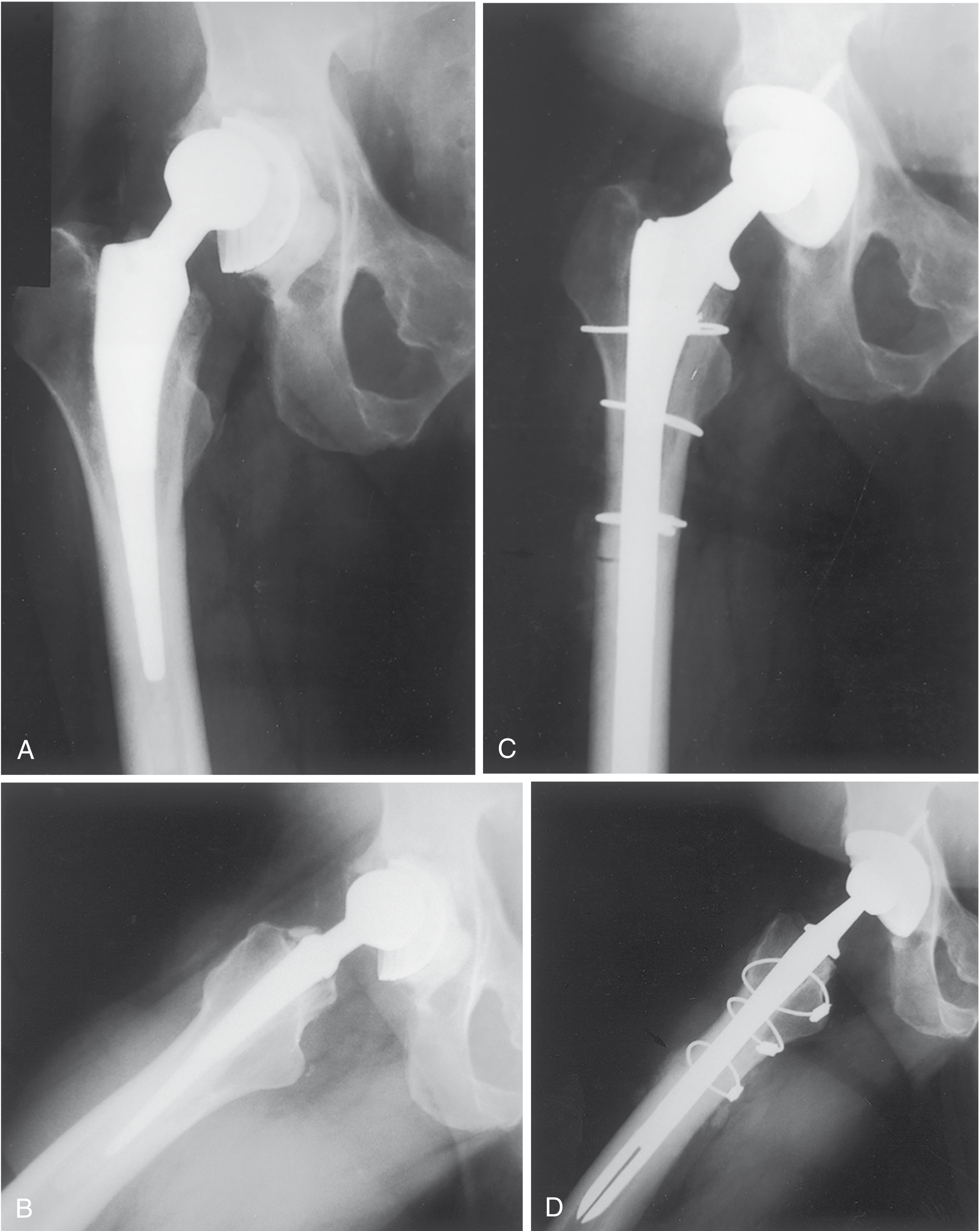
Fixation of the Osteotomy Fragment
Rigid fixation is mandatory for union. Options:
- Multiple cerclage cables (most common) - 2-4 cables; provide circumferential compression
- Cable-plate systems (e.g., Accord plate) - proximal hooks capture the trochanteric fragment; plate extension fixed to femur with cerclage cables; provides better resistance to shear and proximal migration
- Cortical allograft struts - placed over the lateral cortex and secured with cables; used when the fragment is thin/osteopenic; provides mechanical reinforcement and biological union potential
Principles of fixation:
- Hip must not be abducted >10-15 degrees during reattachment - excess strain causes avulsion and nonunion
- Anatomic reduction or slight distal overlap leads to union within 6 months
- Fragment with superior or medial tilt invariably leads to delayed union or nonunion
- Compression across the osteotomy is essential
Postoperative Protocol
- Weight bearing: Toe-touch or partial weight bearing for 8-12 weeks
- Hip precautions: Avoid extreme flexion, adduction, and internal rotation; abduction brace in selected patients
- Serial radiographs at 6 weeks, 3 months, and 6 months to assess union
- Graduated abductor strengthening once radiographic callus is confirmed
- Full weight bearing typically at 3 months if union progressing well
Outcomes
| Parameter | Result |
|---|---|
| Union rate | 93% (meta-analysis) |
| Stem subsidence >5 mm | 7% |
| Dislocation rate | 3.7% (systematic review) |
| Aseptic loosening | ~1% |
(Campbell's Operative Orthopaedics, 15th Ed, p. 338)
Complications
Intraoperative
- Uncontrolled fracture propagation distally - prevented by prophylactic distal cerclage
- Sciatic nerve injury - must be protected; risk increased with limb lengthening
- Vascular injury - superficial femoral artery at risk during cable passage
- Fragment comminution - in osteoporotic bone
Early Postoperative
- Dislocation - abductor disruption increases risk (~3.7%; higher in periprosthetic fracture cases)
- Infection - increased by longer operative time and blood loss
- Fragment displacement or proximal migration - fixation failure
Late
- Trochanteric nonunion - most significant complication; up to 20% in some series; leads to:
- Trendelenburg gait and lurch
- Abductor weakness with hip instability
- Persistent pain and reduced function
- Cerclage wire/cable breakage - common even after solid union; usually not clinically significant
- Stem subsidence (~7%) - especially if cement intrudes into osteotomy site
- Heterotopic ossification - prophylaxis considered in high-risk patients
- Femoral component aseptic loosening (~1%)
- Trochanteric bursitis from prominent hardware
Modified Techniques
- Lakstein modification: Posterior capsule and short external rotators left intact to reduce dislocation risk
- Wagner (anteriorly-based) osteotomy: Anteriorly based rather than laterally based; used when lateral cortex is thin
- Paprosky (laterally-based) osteotomy: Standard ETO as described - most widely used
Summary Table
| Feature | Detail |
|---|---|
| Originally described by | Younger et al. |
| Fragment | ~1/3 circumference of femur (lateral wall) |
| Muscles on fragment | Gluteus medius + minimus (proximal), Vastus lateralis (distal) |
| Approach | Posterolateral |
| Preferred reconstruction | Cementless (cement inhibits union) |
| Isthmus preserved | 5-6 cm (for revision stem contact) |
| Revision stem bypass | 2 cortical diameters (~5 cm) below osteotomy |
| Fixation | Cerclage cables ± cable plate ± strut allograft |
| Union rate | 93% |
| Key complication | Trochanteric nonunion - Trendelenburg gait |
Sources: Campbell's Operative Orthopaedics 15th Ed (2026), Techniques 4.11 and 4.15, pp. 279-340; PMC review on trochanteric osteotomy variants; IntechOpen ETO chapter
Direct vertebral rotation ms ortho 20 marks answer
Reading File
Finding Sources
Finding Sources
Searching the Web
direct vertebral rotation DVR scoliosis technique mechanism indications outcomes
Found the dedicated section in Campbell's. Let me read it fully along with surrounding context.
Reading File
Finding Sources
Reading File
Finding Sources
Reading File
Finding Sources
Reading File
Loading Image
Now let me get the broader context on scoliosis, surgical indications, and Lenke classification from the book, plus the outcomes section.
Finding Sources
Finding Sources
Finding Sources
Searching the Web
direct vertebral rotation DVR vs rod derotation scoliosis mechanism biomechanics Lee Suk 2004
I now have comprehensive material from Campbell's plus the primary literature. Let me write the full 20-mark answer.
Direct Vertebral Rotation (DVR)
MS Orthopaedics - 20 Marks Answer
Introduction
Scoliosis is a three-dimensional deformity of the spine involving:
- Coronal plane - lateral curve (Cobb angle)
- Sagittal plane - loss of normal kyphosis/lordosis
- Transverse (axial) plane - vertebral rotation (responsible for rib hump and cosmetic deformity)
Traditional correction techniques using rod derotation (Harrington, Cotrel-Dubousset) addressed the coronal and sagittal planes well but had limited effect on the critical transverse plane rotational deformity. Direct Vertebral Rotation (DVR) was developed specifically to address this gap.
Definition
Direct Vertebral Rotation (DVR) is a surgical technique for three-dimensional correction of spinal deformity in adolescent idiopathic scoliosis (AIS), in which screw derotators are applied directly to bilateral pedicle screws at the apical and juxta-apical vertebrae and the vertebrae are physically rotated in the transverse plane - opposite to the direction of their pathological rotation - to achieve axial derotation that cannot be accomplished by rod rotation alone.
First described by: Lee SM, Suk SI, and Chung ER (Spine, 2004) - "Direct vertebral rotation: a new technique of three-dimensional deformity correction with segmental pedicle screw fixation in adolescent idiopathic scoliosis."
Background: Pathomechanics of Scoliosis Deformity
In a right thoracic scoliosis (most common, Lenke Type 1):
| Plane | Deformity |
|---|---|
| Coronal | Right lateral curve; Cobb angle measurement |
| Sagittal | Thoracic hypokyphosis (flattening) |
| Axial/transverse | Vertebrae rotate to the right (clockwise when viewed from above); bodies go right, spinous processes go left; ribs on right side pushed posteriorly = rib hump |
The apical vertebra has maximum rotation; juxta-apical vertebrae have intermediate rotation. The rib hump is primarily determined by this axial rotation.
Limitations of Simple Rod Derotation (SRD)
In rod derotation (the classic technique), the pre-contoured rod is inserted on the concave side and rotated ~90° to translate the lateral curve into a kyphosis (French technique / Cotrel-Dubousset concept). This produces:
- A posteromedial vector force that corrects the coronal curve
- The rod rotates on its own axis, which may paradoxically aggravate vertebral rotation in severe/rigid curves (because the direction of rod rotation axis coincides with the direction of vertebral rotation)
- In mild/flexible curves, the screw may glide on the rod, providing some but incomplete rotational correction
- Axial/transverse plane correction is minimal and unreliable with rod derotation alone
This was the key biomechanical insight of Lee and Suk (2004): rod derotation does not reliably correct vertebral axial rotation, and in some cases worsens it.
Principle of DVR
DVR uses bilateral pedicle screws as handles to directly rotate individual or multiple vertebrae in the transverse plane:
- The derotation is applied directly to the vertebral body via pedicle screws (which traverse the pedicle and enter the vertebral body)
- Force is applied simultaneously from both concave and convex sides
- Direction: opposite to the pathological vertebral rotation
- For right thoracic scoliosis: vertebrae are rotated counter-clockwise (correcting the clockwise pathological rotation)
- The procedure is performed en bloc (multiple levels simultaneously) using a Vertebral Column Manipulator (VCM), or sequentially at individual levels
"The direct vertebral rotation is opposite to that of the vertebral rotation in the thoracic curve; apical and juxta-apical vertebrae are rotated clockwise for right thoracic curves in the transverse plane." (Campbell's Operative Orthopaedics, 15th Ed, Technique 40.14, p. 2027)
Wait - to clarify: the vertebral bodies in right thoracic scoliosis rotate to the right (clockwise). DVR applies counter-clockwise rotation to correct this. The bodies rotate back toward neutral.
Prerequisite: Segmental Pedicle Screw Fixation
DVR is only possible with bilateral pedicle screw instrumentation at every level to be fused. This is because:
- Hooks and sublaminar wires do not provide a strong enough purchase to transmit rotational forces to the vertebral body
- Pedicle screws are the only implant that directly engages the vertebral body via the pedicle
- Bilateral screws at each level are needed to apply a couple force (not just a unidirectional force) allowing true rotation rather than translation
This is why DVR became clinically feasible only after the widespread adoption of segmental bilateral pedicle screw systems.
Instrumentation - Vertebral Column Manipulator (VCM)
The standard instrument for DVR is the Vertebral Column Manipulator (VCM) (Medtronic Sofamor Danek):
- Implant holders (derotator tubes) are attached to pedicle screws on both concave and convex sides
- Connected to each other by preloaded bridge nuts/cross-connectors at their cephalad ends - creating a triangulated or quadrilateral rigid construct
- For flexible curves: single triangulated segment at apex
- For large/rigid curves: quadrilateral frame connecting apical and juxta-apical vertebrae
- Handles allow application of rotational forces:
- Superior handle (vertical): controls rotation
- Convex horizontal handle: aids in directionality
- The entire construct rotates the scoliosis apex en bloc in the transverse plane
Surgical Technique (Technique 40.14, Campbell's Operative Orthopaedics, 15th Ed)
Patient position: Prone on radiolucent table, with adequate padding to allow chest movement.
Approach: Posterior midline approach, full subperiosteal exposure.
Step-by-Step:
1. Bilateral pedicle screw insertion at every level to be fused in the thoracic spine.
- This is mandatory - unilateral screws are insufficient for DVR
- Screws must be accurately placed (free-hand technique, fluoroscopy, or navigation)
- The direct vertebral rotation direction is opposite to the vertebral rotation in the thoracic curve; for right thoracic curves, apical and juxta-apical vertebrae are rotated clockwise in the transverse plane (i.e., the correction is counter-clockwise/anti-clockwise for the body rotation)
- Identify the neutral (least rotated) vertebra distally and begin derotation proximal to this level
2. Neurophysiological monitoring - obtain baseline motor-evoked potential (MEP) measurements before any reduction maneuver
- A mean arterial pressure (MAP) of at least 70 mmHg must be maintained throughout, because corrective forces placed on the spine can compromise spinal cord perfusion
3. Screw derotators are placed onto the pedicle screws of the juxta-apical vertebrae on both the concave and convex sides
- Derotate the vertebrae as much as possible
- This can be done en bloc (multiple levels simultaneously) or at each individual level
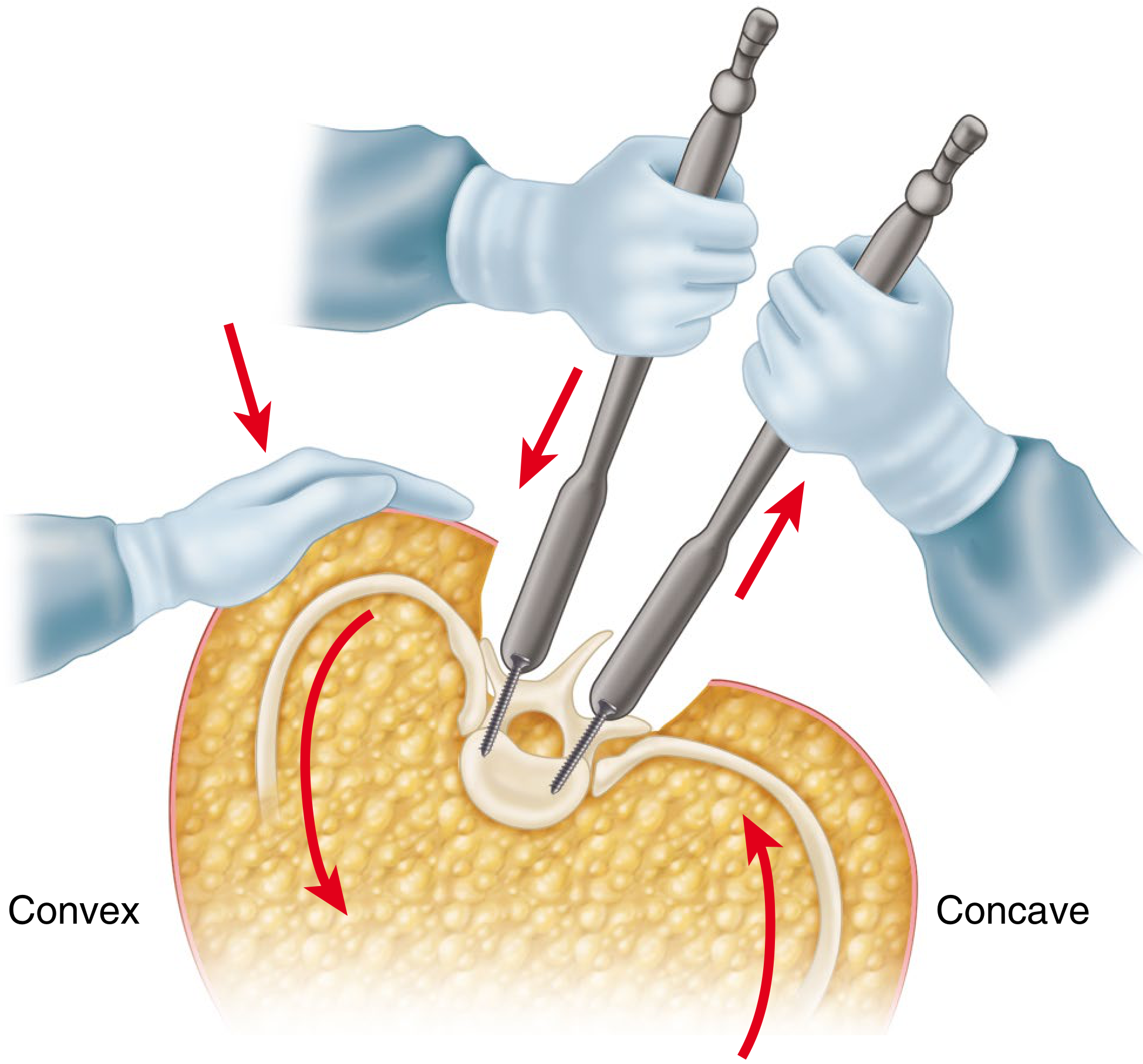
4. Simultaneous forces during rod derotation:
- Push down on the convex screws and pull up on the concave screws simultaneously
- An assistant applies downward pressure on the convex apical ribs to aid in derotation
- This combined maneuver corrects deformity in all three planes simultaneously
5. Lock the rod into position by tightening set screws fully after completion of derotation
- This process can be repeated multiple times until the desired correction is obtained
6. For rigid curves: if little rod derotation is possible, other techniques such as rod bending, ponte osteotomies, or facetectomies must be combined
7. Postoperative care:
- With modern rigid segmental instrumentation, patients ambulate immediately after surgery
- Bracing is rarely required
- Multimodal pain management and accelerated discharge protocols are used
- One study showed 31% decrease in hospital stay with such protocols
DVR in Different Curve Patterns (Suk Classification)
| Curve Pattern | DVR Direction |
|---|---|
| Right thoracic (most common) | Counter-clockwise rotation of apical vertebrae |
| Left thoracolumbar/lumbar | Clockwise rotation of apical vertebrae |
| Double major curves | DVR direction is the same for both thoracic and thoracolumbar curves |
| Lenke Type 1 (right thoracic) | Most commonly treated; best studied |
The direction of DVR is always opposite to the pathological vertebral rotation.
Advantages of DVR over Simple Rod Derotation
| Feature | Simple Rod Derotation | Direct Vertebral Rotation |
|---|---|---|
| Planes corrected | Coronal + Sagittal | Coronal + Sagittal + Axial |
| Mechanism | Indirect (via rod shape) | Direct (via pedicle screws) |
| Rotational correction | Minimal/unreliable | Superior |
| Rib hump correction | Modest | Better |
| Effect on rigid curves | Limited; may worsen rotation | Superior force transmission |
| Implant requirement | Pedicle screws | Bilateral pedicle screws mandatory |
| Fusion length | Standard | May allow shorter fusion |
Indications
- Adolescent idiopathic scoliosis (AIS) - primary indication; all Lenke curve types
- Significant apical vertebral rotation - particularly where rib hump is the primary cosmetic concern
- Rigid/severe curves (Cobb angle >45-50°) - where rod derotation alone is insufficient
- Thoracic curves - best results; also applicable in thoracolumbar and lumbar curves
- When bilateral pedicle screw construct is being used
- As a supplementary maneuver to rod derotation in all three-dimensional corrections
Contraindications / Limitations
- Unilateral or hook/wire constructs - DVR cannot be performed without bilateral pedicle screws
- Severe osteoporosis - risk of screw pullout during derotation forces
- Very rigid curves - may require supplementary osteotomies (Ponte, Smith-Petersen)
- Neurological deficits requiring cautious force application
Outcomes and Evidence
| Study | Finding |
|---|---|
| Lee, Suk, Chung (Spine, 2004) - Original paper | DVR showed significantly better rotational and coronal correction than simple rod derotation (SRD) |
| Suk et al. (2004) | Significant difference in apical vertebral rotation: DVR superior to SRD |
| Archives of Orthop & Trauma Surg (Springer, 2017) | DVR produced greater reduction in axial rotation; more pronounced in adolescents and flexible curves |
| J Turkish Spinal Surgery (comparative cohort) | No significant difference in coronal Cobb angle correction between DVR and rod derotation; both achieved satisfactory coronal results |
| PMC (Urbanski et al., 2023) | DVR did not improve clinical and radiological outcomes vs. differential rod contouring in all subgroups; DVR more effective in flexible thoracic curves in adolescents |
Current consensus: DVR provides superior axial vertebral rotation correction, particularly in the thoracic spine and in flexible curves in adolescents. The effect on coronal correction is comparable to rod derotation. DVR and rod derotation both cause similar thoracic hypokyphosis (related to all-pedicle-screw instrumentation rather than DVR per se).
Complications
- Neurological deficit - most serious; risk from forceful derotation; prevented by continuous intraoperative neuromonitoring (IONM) with MEP and SSEP
- Spinal cord ischemia - from reduced spinal perfusion during derotation; prevented by maintaining MAP ≥70 mmHg
- Pedicle screw pullout - during derotation forces; risk with osteoporosis or misplaced screws
- Pedicle fracture - from excessive rotational force
- Incomplete derotation - in rigid curves; may need supplementary osteotomies
- Proximal junctional kyphosis (PJK) - if instrumentation ends at a sagittal apex; use stable sagittal vertebra (SSV) concept
- Distal junctional kyphosis (DJK) - ends in middle of structural curve; use Lenke criteria for level selection
- Coronal decompensation - with selective thoracic fusion; lower instrumented vertebra should touch center sacral line
- Infection, pseudarthrosis, implant failure - general spinal fusion complications
Comparison with Other Derotation Methods
| Technique | Mechanism | Plane |
|---|---|---|
| Harrington distraction | Pure distraction on concave side | Coronal only |
| Cotrel-Dubousset rod derotation | Rod shape + rotation | Coronal + sagittal |
| Direct Vertebral Rotation (DVR) | Direct vertebral force via pedicle screws | All three planes |
| Vertebral Coplanar Alignment (VCA) | Translational + rotational | All three planes |
| Differential Rod Contouring (DRC) | Overbent convex + flat concave rod | Indirect axial derotation |
| Ponte osteotomies + DVR | Release + derotation | Best for rigid curves |
Summary / Key Points
| Point | Detail |
|---|---|
| Described by | Lee SM, Suk SI, Chung ER (Spine, 2004) |
| Deformity addressed | Transverse plane (axial vertebral rotation) |
| Prerequisite | Bilateral pedicle screws at every fusion level |
| Direction of correction | Opposite to pathological vertebral rotation |
| Right thoracic curve DVR | Counter-clockwise (anti-clockwise) rotation |
| Instrument | Vertebral Column Manipulator (VCM) |
| Levels targeted | Apical + juxta-apical vertebrae |
| MAP requirement | ≥70 mmHg during derotation maneuvers |
| Monitoring | Continuous MEP + SSEP |
| Advantage over SRD | Superior axial rotation + rib hump correction |
| Postoperative | Immediate ambulation; bracing rarely needed |
Sources: Campbell's Operative Orthopaedics 15th Ed (2026), Technique 40.14, p. 2027-2028; Lee SM, Suk SI, Chung ER. Direct vertebral rotation. Spine. 2004;29:343-349; Urbanski et al. PMC10299005 (2023); Springer Archives Orthop Trauma Surg DVR impact
This is a shared conversation. Sign in to Orris to start your own chat.